Unit-1
Crystal Structure
A small 3D representative Structural subunit of lattice is called unit cell.
A unit cell is the smallest repeating portion of a crystal lattice. Unit cells occur in many different varieties. As one example, the cubic crystal system is composed of three different types of unit cells:
(1) Simple cubic,
(2) face-centred cubic, and
(3) body-centred cubic.
Key Takeaways:
The metallic structure is formed by associating every lattice point with an assembly or atoms or molecules or ions which are identical in composition, arrangement and orientation.
Crystal Structure has three types of unit cells which are mostly being used:
BCC Structure has atoms at its each corner and one atom at its centre. So, the BCC consists of net total of two atoms.
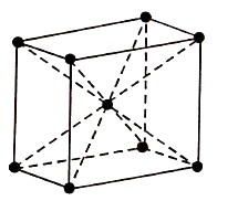
Figure 1: BCC
Therefore, Total atoms in the BCC = (1/8) × 8+1=2
The coordination number of BCC arrangement is 8 and packing factor is 0.68.
The BCC structure can be generally seen in Lithium, Potassium, and Sodium etc.
2. Face Centred Cubic Structure (FCC):
It consists of atoms at its each corner and one atom at centre of each face.
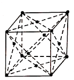
Figure 2: FCC
Total atoms in FCC Unit cell= (1/8) × 8+ (1/2) × 6
=1+3
=4 atoms.
The coordination number is 12 and packing factor is 0.74.
The FCC structure can be generally seen in Copper, Gold, Silver and Lead etc.
3. Hexagonal Closed-Packed Structure ( HCP):
The unit cell is like a hexagonal prism in HCP.

Figure 3: HPC
There are twelve corners and each corner have an atom and one atom at the centre of each of the two hexagonal faces and three atoms in the body of the cell. In total, seventeen atoms take part in formation of a HCP unit cells.
Total atoms in HCP =12× (1/6) +3+2 × (1/2) = 6 atoms.
This is identical to FCC, having coordination number 12 and packing factor 0.74.
This HCP structure is generally seen in Zinc, Magnesium and Beryllium etc.
A ceramic is any of the various hard, brittle, heat-resistant and corrosion-resistant materials made by shaping and then firing a non-metallic mineral, such as clay, at a high temperature. Common examples are earthenware, porcelain, and brick.
Ceramics are generally made by taking mixtures of clay, earthen elements, powders, and water and shaping them into desired forms. Once the ceramic has been shaped, it is fired in a high temperature oven known as a kiln. Often, ceramics are covered in decorative, waterproof, paint-like substances known as glazes.
There are basically five types of ceramics are known:
Those four vary in accordance to the clay used to create them, as well as the heat required to fire them.
Key Takeaways:
If any departure or randomness occurs in a perfectly ordered arrangement of atoms, then the crystal is termed as imperfect. The following imperfections are mentioned below:
n =Ne-Ed/kT
Where, n = Number of imperfections
N= Number of atomic sites per mole,
k =Boltzman constant
Ed = the free energy required to form the defect, and
T= Absolute temperature.
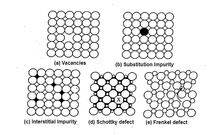
Figure 4: point imperfections
2. Line Imperfections:
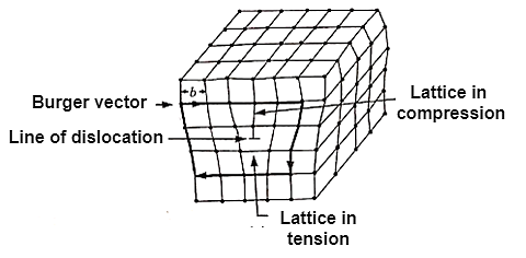
Figure 5: Line Imperfection or dislocation
Causes of line imperfections are:
Types of line imperfections:
It is formed by adding extra partial planes of atoms.
b. Screw line imperfection or dislocation:
A screw dislocation has its displacement or Burger Vector parallel to the linear defect but there is a distortion of the plane.
These dislocations are responsible for the useful property of ductility in metal, ceramics and polymers.
3. Interfacial Imperfections:
Interfacial defects can be defined as boundaries that have two dimensional imperfections in crystalline solid, and have different crystal structures and or crystallographic orientations on either side of them. They refer to the regions of distortions that lie about a surface having thickness of few atomic diameters. For example external surface, grain boundaries, twin boundaries, stacking faults and phase boundaries. These imperfections are not thermodynamically stable, rather than they are meta-stable imperfections. They arise from the clustering of line defects into a plane.
4. Volume or Bulk imperfections:
Volume defects as name suggests are defects in 3-D dimensions. These include pores, cracks, foreign inclusions and other phases. These defects are normally introduced during processing and fabrication steps. All these effects are capable of acting as stress raisers, and thus deleterious to parent metal’s mechanical behaviour. However in some cases foreign particles are added purposefully to strengthen the parent material. The procedure is called dispersion hardening where foreign particles acts as a obstacles to movement of dislocation which facilitates the plastic deformation. The second phase particle act in two distinct ways- particles are either may be cut by the dislocations or the particle cutting and dislocations are forced to bypass them. Strengthening due to ordered particles is responsible for the good high-temperature strength on many super-alloys. However, pores are detrimental because they reduce effective load bearing area and act as stress concentrations sites.
The ability of metal to deform depends on the ability of dislocations to move.
Restricting the dislocation motion makes the material stronger.
Mechanism for strengthening in single phase metals:
Ordinarily, strengthening reduces ductility.
Grain boundary barrier to dislocation motion: slip plane discontinues or change orientation.
Small angle grain boundaries are not very effective in blocking dislocations.
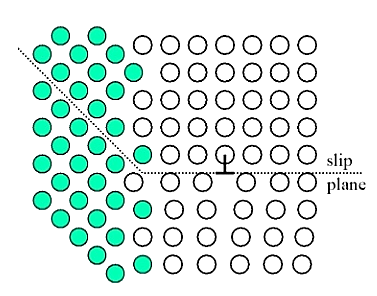
Figure 6: Grain size reduction
High angle grain boundaries block slip and increase strength of material. A stress concentration at end of a slip plane may trigger new dislocations in an adjacent grain.
The finer the grains, larger the area of grain boundaries that impedes dislocation motion. It usually improves the toughness as well. Usually, the yield strength varies with grain size d according to the hall Petch equation.

Where σ0 and ky are constant for a particular material, d is the average grain diameter.
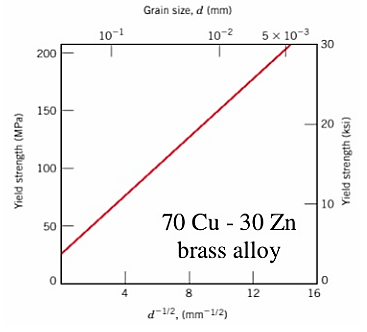
Figure 7: Graph for grain size reduction
2. Solid solution alloying:
Interstitial or substitutional impurities cause lattice strain. As a result, these impurities interact with the dislocation strain fields and hinder dislocation motion.
Impurities tend to diffuse and segregate around dislocation cores to find atomic sites that suit their radii. This reduces their overall strain energy and anchors the dislocations.
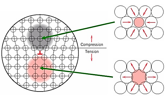
Figure 8: Solid Solution alloying Strengthening
Motion of dislocation core away from the impurities moves it to a region of lattice where the atomic strains are greater.
3. Strain hardening strengthening:
Ductile metals become stronger when they are deformed plastically at temperatures well below the melting point.
The reason for strain hardening is the increase of the dislocation density with plastic deformation. The average distance between dislocations decrease and dislocation starts blocking the motion of each other.
The percent cold work is often used to express the degree of plastic deformation.
Slip is lose one’s footing and slide and unintentionally for a short distance or to fall down. Slip Direction is the direction in which the dislocation moves, which is the Burger vector for the edge locations.
A plane surface through a crystal along which slip can take place under some conditions without apparently disrupting the crystal.
Slip planes are the plane with the highest density of atoms.
Slip does not move at the same degree of ease on all crystallographic planes and direction of atoms.
The preferred plane with specified directions along which dislocation motion occurs is called slip planes.
The combination of slip planes and the slip direction is known as slip system.
For a particular crystal structure:
There are types of slip system:
Slip results in the formation of steps the surface of the crystal. These are readily detected if the surface is carefully polished before plastic deformation.
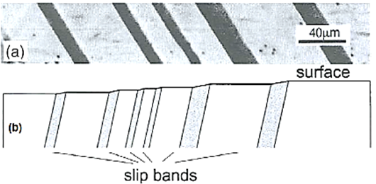
Figure 9: Slip bands
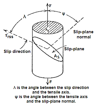
Erich Schmid discovered that if a crystal is stressed, slip begins when the shear stress on a slip system reaches a critical value, Ϡc, often called the critical resolved shear stress. In the most crystals, slip occurs with equal ease forward or backward, so a characteristic shear stress is required for slip.
Consider a crystal with a cross-sectional area A0 being deformed in tension by an applied force F along the axis of the cylindrical crystal.
Key Takeaways:
The active slip system will have the largest Schmid factor.

Reference: