Unit - 3
Mechanical Properties Measurement
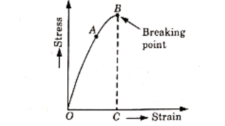
- The stress-strain diagram for brittle material, in which the axial strain are plotted along x-axis and corresponding stresses (P/A)=(Load/Area) are plotted along y-axis.

Figure 1: Stress-strain diagram for brittle material
- The diagram is obtained by performing a tensile test on the specimen.
- The end of the test piece is fixed into grips connected to a straining device and load measuring device. The load on the test piece is increased slowly and corresponding extension is measured. From these readings, the curve OAB is obtained.
- In this curve, from O to A the stress is proportional to the strain and this is known as elastic edge stage.
- Upto point A, Hooke’s law is applicable. The stress at A represents the proportional limit.
- If the load is increased further the elongation becomes more rapid and diagram becomes curved. This stress will not be proportional to the strain.
- At point B, suddenly the specimen breaks into pieces. The total elongation OC before fractures is very small as compared to total elongation of ductile materials.
Key takeaways:
- If the load is increased further the elongation becomes more rapid and diagram becomes curved. This stress will not be proportional to the strain.
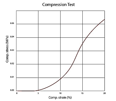
Compression tests are used to determine a material's behaviour under applied crushing loads, and are typically conducted by applying compressive pressure to a test specimen (usually of either a cuboids or cylindrical geometry) using platens or specialized fixtures on a universal testing machine.
During the test, various properties of the material are calculated and plotted as a stress-strain diagram which is used to determine qualities such as elastic limit, proportional limit, yield point, yield strength, and, for some materials, compressive strength.
Compression testing allows manufacturers to assess the integrity and safety of materials, components, and products during several phases of the manufacturing process. The potential applications can vary from strength testing of a car windshield to endurance testing of concrete beams used in construction. Materials that exhibit high tensile strength tend to (but do not always!) exhibit low compressive strength. Likewise, materials high in compressive strength tend to exhibit low tensile strength. Therefore, compression testing is often used on brittle materials such as concrete, metals, plastics, ceramics, composites, and corrugated materials like cardboard. These materials are often used in a load-bearing capacity where their integrity under compressive forces is critical.

Figure 2: Compression test
Key Takeaways:
- Compression tests are used to determine a material's behaviour under applied crushing loads, and are typically conducted by applying compressive pressure to a test specimen
Torsion tests twist a material or test component to a specified degree, with a specified force, or until the material fails in torsion. The twisting force of a torsion test is applied to the test sample by anchoring one end so that it cannot move or rotate and applying a moment to the other end so that the sample is rotated about its axis. The rotating moment may also be applied to both ends of the sample but the ends must be rotated in opposite directions. The forces and mechanics found in this test are similar to those found in a piece of string that has one end held in a hand and the other end twisted by the other.
Types of Torsion test:
The three common forms that torsion testing take include failure, proof and operational. A torsion test for failure requires that the test sample be twisted until it breaks and is designed to measure the strength of the sample. A proof test is designed to observe the material under a specified torque load over a set period of time. Finally, operational testing is measures the material’s performance under the expected service conditions of its application. All of these forms of tests may be performed with either torsion only loading or a combination of torsion and axial (tension or compression) loading depending upon the characteristics to be measured.
Types of Torsion Testing Materials:
Many materials experience torques or torsional forces in their applications and so will benefit from or require torsion testing. Materials used in structural, biomedical and automotive applications are among the more common materials to experience torsion in their applications. These materials may be composed of metals, plastics, woods, polymers, composites, or ceramics among others and commonly take the forms of fasteners, rods, beams, tubes and wires.
Key Takeaways:
- Torsion tests twist a material or test component to a specified degree, with a specified force, or until the material fails in torsion.
Young's Modulus is constant coefficient stiffness, named k, which describes how stiff the skin or how likely is it is to deform.
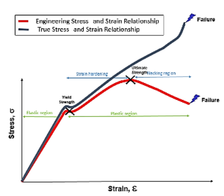
Stress-strain curve for material is plotted by elongating the sample and recording the stress variation with strain until the sample fractures. The strain is set to horizontal axis and stress is set to vertical axis. It is often assumed that the cross-section area of the material does not change during the whole deformation process. This is not true since the actual area will decrease while deforming due to elastic and plastic deformation. The curve based on the original cross-section and gauge length is called the engineering stress-strain curve, while the curve based on the instantaneous cross-section area and length is called the true stress-strain curve.

Figure 3: Stress-strain curve of true and engineering curve (Yasin CAPAR)
For engineering stress, we assume the length and diameter of the sample remain constant throughout the whole experiment.
Engineering stress is calculated by:

 Engineering strain is calculated by:

Key Takeaways:
- True stress is the applied load divided by the actual cross-sectional area (the changing area with time) of material. Engineering stress is the applied load divided by the original cross-sectional area of material.
Hooke's law is a fundamental rule of thumb applied on skin that describes a direct proportionality link between the force applied on an object and the induced strain
- In materials science and engineering, the yield point is the point on a stress-strain curve that indicates the limit of elastic behaviour and the beginning of plastic behaviour.
- Below the yield point, a material will deform elastically and will return to its original shape when the applied stress is removed.
- Once the yield point is passed, some fraction of the deformation will be permanent and non-reversible and is known as plastic deformation.
- Yield strength is defined as the stress at which a material begins to deform plastically.
- The plastic deformation begins at a point known as yield point.
- The yield point determines the limits of performance for mechanical components, since it represents the upper limit to forces that can be applied without permanent deformation.
Ductility is a property that measures the degree of plastic deformation that has been sustained at fracture.
A material that experiences very little or no plastic deformation upon fracture is termed brittle. Ductility may be expressed quantitatively as either percent elongation or percent reduction in area. The percent elongation %EL is the percentage of plastic strain at fracture, or
%EL=(lf-lo)/(lo)×100
Where, lf=Fracture length, and
lo= Original gauge length
In material science, resilience is the ability of a material to absorb energy when it is deformed elastically, and release that energy upon unloading. Proof resilience is defined as the maximum energy that can be absorbed up to the elastic limit, without creating a permanent distortion.
Thus, resilient materials are those having high yield strengths and low moduli of elasticity such alloys are used in spring applications. The energy expended in deforming the spring is stored in it and can be recovered when the spring returns to its original shape.
The term toughness is defined as the property of metal by virtue which it can absorb maximum energy before fracture takes place.
Tenacity and hardness of a metal are the measures of its toughness.
It has been found the value of toughness fall with the rise in temperature.
Toughness of materials is indicated by the total area under the material tensile stresses-strain curve up to the point of fracture.
Elastic recovery, or resilience, is a measure of the ability of an elastomer to return to its original shape when a compression load is removed. Ideally a seal should have a good resilience which can be largely controlled by compounding.
Ideally a seal should have a good resilience which can be largely controlled by compounding. It is a peculiarity of many elastomers, however, that resilience can vary widely with temperature, and with a sharply defined minimum value which commonly occurs in the range of –20 to +20 °C. Some elastomers, notably silicones, retain substantially constant resilience over a wide range of temperatures.
A low rating is desirable for dynamic seals, where recovery is important; this may refer to compression set or tension set and is a measure of the permanent change in original dimension after being compressed, or stretched, under compressive or tensile loading, respectively.
Compression Set is significant in that because most seals are loaded in compression some permanent reduction in dimension or shrinkage will occur, by the amount of set characteristic for that material. This may, however, be offset by other factors, such as swelling of the seal in contact with the fluid or can be allowed for in seal design.
Excessive Tension Set may result in a seal ring being a loose fit after being stretched in place over a rod because the seal does not recover to its original inside diameter to which the groove was matched. This would probably be offset by compression set on completion of the assembly and so tension is normally ignored.
The latter may be significant in plastomers which have low elongation and slow recovery, particularly if over-stretched. Both elastomers and plastomers, however, if loaded in tension, or with residual tensile stresses, will tend to contract with an increase in temperature.
The term “hardness” is defined as the property of metal by virtue of which it is able to resist abrasion, indentation (or penetration) and scratching by harder bodies.
It is measured by the resistance of the metal which it offers.
3.13.1 The Rockwell hardness:
This test is widely used because of its speed and freedom from personal errors.
This test requires much smaller penetrators and loads than used on Brinell hardness testers.
There are two scales on a Rockwell hardness testing machine, B-scale and C-scale.
While performing the Rockwell hardness test the following procedure is used:
- The test piece is placed on the machine’s test table.
- The test piece is raised by turning the hand wheel, till it just touches the indicator and the needle on the machine dial reads zero. This indicates that a minor load of 10 kg has been applied on the test sample by the machine and ensures is seated properly.
- After that a major load of 100 kg (for B-scale) or 150 kg (for C-scale) is applied by pressing the crank provided for this purpose.
- The depth of the indentation is recorded automatically by means of a dial scale. The reading is correlated with arbitrary hardness numbers.
3.13.2 Brinell hardness:
In this test a standard hardened steel ball of diameter D is presented into the surface of the specimen by a gradually applied load P which is maintained on the specimen for a definite period of time.
The impression of the steel ball (indentor) so obtained is measured by a microscope and the Brinell hardness number (BHN) is found by the following relations:
BHN=
=
P= Applied load, D= Diameter of steel ball and d=diameter of the impression, measured with a microscope.
A Brinell hardness tester is shown in figure below:

Figure 4: Brinell Hardness tresting
The test sample is placed on the top of the test table which can be which can be raised by the elevating screw so that test sample just touches the ball.
The desired load is applied either mechanically or by oil pressure.
During this period the steel moves to the position of the sample and makes an impression or indentation.
The indentation diameter is measured at two places, either on the screen provided with the machine or by coinciding the two points of the reading microscope.
3.13.3 Vickers hardness:
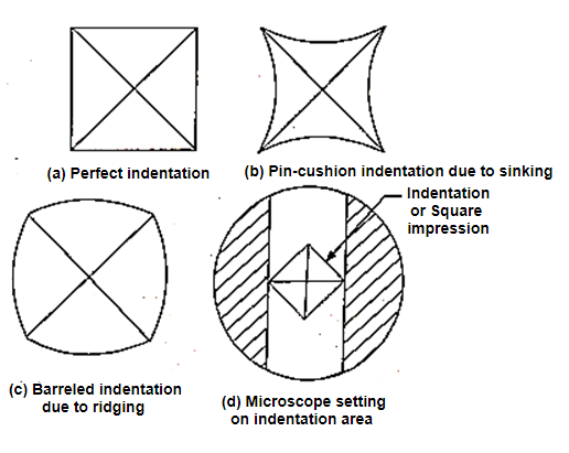
In this method of hardness testing a square-based diamond pyramid is used as indentor.
The drawback of the flattening of the steel ball in testing harder material is eliminated.
This method uses the indentation produced by the indentor which gives geometrically similar impression under different load from 5 to 120 kg.

Figure 5: Vicker’s hardness testing
The value of Vicker’s hardness can be obtained by the following expression:

Where, VPN= Vicker’s Pyramid Number
DPN=Diamond Pyramid Number
P= Load in kg
Θ= 136 degree =angle between opposite face of diamond pyramid
d =Average length of two diagonals, mm.
This method is used to determine the hardness of very thin and very hard material. It also facilitates the ease of measurement of the diagonal of the indentation area, as compared to circular dimensions to measure exactly.
The value of Brinell and Vicker’s hardness is practically the same upto 300. Vicker’s test can be carried out accurately on polished surface but does not give accurate results when used for rough surface.
Non-destructive testing refers to a method of detecting internal flaws in engineering materials without breaking them.
It can be also be defined as the use of non-invasive technique to determine the integrity of a material component or structure or quantitatively measuring some characteristics of an object.
NDT is aimed at extracting information on the physical, chemical, mechanical or metallurgical state of material or structures without damaging its intended utility value.
Scope of NDT:
- In mechanical or optical-strain distribution, surfaces flaws, cracks, gagging, dimensions etc.
- In Automotive-engine parts, frames and other accessories.
- Aviation field-space and air frame.
- New big sector power plant-propeller, engines, gas turbines, heat exchangers, etc.
- Railways for rail/wheel/corrosion inspection.
- Construction of bridges, structures.
- Manufacturing of machine parts, casting, forging etc.
- Medical applications.
- Submarines and Naval ships.
Advantages of NDT:
- It ensures the integrity and reliability of a product.
- Time and money saving, because these are fast methods.
- Higher customer’s satisfaction and preventing accidents and saving lives.
- Production, inspection and labour costs are reduced.
- Maintain a uniform quality level; NDT can help to establish a quality level.
- Products demand increased.
- Easy material handling and one way process control.
- Alloy identification, degree of cure, corrosion etc. are detected by NDT.
- NDT plays very important parts in the designing of lighter, stronger and less costly reliable parts.
There are various NDT methods which have been used from long time. Some of them are mentioned below:
- Visual and Optical testing:
It may be performed manually by an inspector or by special automated technique like magnifying glasses, mirrors, or boroscope to gain access and more closely inspect the component.
2. Penetrate testing:
In this method, test specimen is coated with liquid of fluorescent dye solution. Then excess penetrant is removed very carefully and developers are applied.
These developers acts as blotter and draws out the trapped penetrant from defect to open surface. These penetrants are now easily visible because of colour contrast between penetrant and developer with fluorescent dyes. Ultraviolet lights are used which make the bleed out penetrant readily seen.
3. Magnetic particle Testing:
This method employs the role of magnetic field which may be produced by any of the magnetizing technique. Then a powdered magnet or liquid magnet called as magnetic ink is spread over the surface to be inspected.
Surface or near surface defects cuts the magnetic flux line, which generates a new magnetic pole, at the defect point. This concentrates the iron particles near imperfection or defect giving a clear visualization of defect.
Key takeaways:
Non-destructive testing refers to a method of detecting internal flaws in engineering materials without breaking them.
Reference:
- U. C Jindal,” Engineering Materials and Metallurgical”
- V. Raghavan, “Material Science and Engineering”.
- Arpan Singh, “Material Science and Engineering”.
- Various Google sites and ppt.