UNIT 1
Statics
In Statics, we deal with forces and their effects which acts on body during its rest condition.
Scalar and Vectors:
All physical quantities in engineering mechanics are measured using either
scalars or vectors.
Scalar: When a quantity is specified only by its magnitude, then it is known as scalar quantity. E.g. length, mass, and time.
Vector: A quantity that requires magnitude as well as direction for its specification, is known as a vector quantity. E.g. force, moment and position. A vector is shown graphically by an arrow.
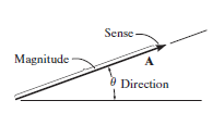
The above displayed figure represents the vector quantity.
Effects of a force:
It may produce the effects on body on which it is acted as:
1. Motion of the body may be changed.
2. It may retard the motion of a body.
3. It may reduce the acting forces to make it stop or be in equilibrium
4. It may even create internal stresses in the body.
Characteristics of a force:
Following are the characteristics of a force:
1. Magnitude of the force (i.e., 100 N, 50 N, 20 kN, 5 kN, etc.)
2. The direction of the line, along which the force acts.
3. Nature of the force. This is denoted by placing an arrow head on the line of action of the force.
4. The point at which (or through which) the force acts on the body.
System of forces:
When two or more forces act, then we called it as the system of forces, like:
1. Coplanar forces: Those having line of action in same plane.
2. Collinear forces. Those whose line of action is in the same line.
3. Concurrent forces. Those which meet at one particular point in space.
4. Coplanar concurrent forces. Those having same plane and meet at one point.
5. Coplanar non-concurrent forces. Those who are in same plane but do not meet at a point.
6. Non-coplanar concurrent forces. Those, which meet at a point in space but are not in same plane.
7. Non-coplanar non-concurrent forces. Those, which do not meet at a point in space nor in the same plane.
Resultant Force:
When many forces are acting, the overall effect can be considered in a single force. This single force is called resultant force and the given individual forces are called component forces.
Methods for the resultant force
Though there are many methods for finding out the resultant force of a number of given forces, yet the following are important from the subject point of view:
Analytical method includes the Parallelogram law of Vectors which is described as “If two forces, acting simultaneously on a particle, be shown by two sides of parallelogram, then the resultant will be the diagonal between these sides of parallelogram.”
Mathematically, resultant force,

Where R is the resultant force, A and B are component vectors and  is the angle between the two vectors, as shown below.
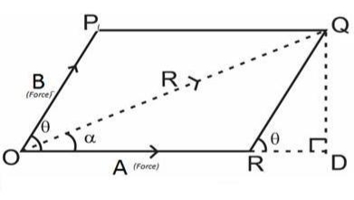
For finding the direction of resultant vector, we need to find the angle between A and R i.e.  .
.

Method of resolution for the resultant force:
1. Horizontal resolution of forces is done and sum is taken (i.e., ∑H).
2. Vertical resolution of forces is done and sum is taken (i.e., ∑V).
3. The resultant R of the given forces will be given by the equation:

4. When the resultant is being inclined by an angle of θ, with the horizontal, we have

Thus, value of the angle θ will vary depending upon the values of ∑V and ∑H as discussed below:
1. When ∑V is +ve, the resultant makes an angle between 0° and 180°. But when ∑V is –ve, the resultant makes an angle between 180° and 360°.
2. When ∑H is +ve, the resultant makes an angle between 0° to 90° or 270° to 360°. But when ∑H is –ve, the resultant makes an angle between 90° to 270°.
Moment of a Force about a point:
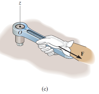
When a force is applied such that it creates rotation at the point of application along line of application, this tendency to rotate is called as torque, or the moment of a force. For example, consider a wrench used to unscrew the bolt in Fig. below.
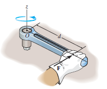
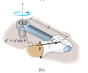
Note that if the force F is applied at an angle less than 900, Fig. (bas moment arm is smaller, it will be more difficult to turn.
If F is applied along the length of wrench, Fig. (c), the moment arm will e zero. Hence moment will also be zero.
Thus, using the above observations, we can generalize accordingly.
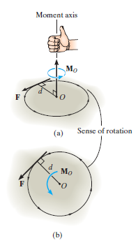
The magnitude of the moment is given by,

where d is the moment arm or perpendicular distance from the axis at point O to the line of action of the force. Units are. N*m or lb*ft.
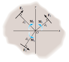
Resultant Moment: For two-dimensional problems, where all the forces lie within the x–y plane, Fig. below, the resultant moment about point O (the z axis) can be determined by finding the algebraic sum of the moments caused by all the forces in the system. As a convention, we will generally consider positive moments as counterclockwise since they are directed along the positive z axis (out of the page). Clockwise moments will be considered to be negative. Doing this, the directional sense of each moment can be represented by a plus or minus sign. Thus, fig. below shows the sign conventions.

As we know that product of Scalar and vector quantity is always a vector quantity. Hence, the Moment of a force or torque is a vector quantity, and can be calculated using cross-product.
The moment of a force F about point O, or actually about the moment axis passing through O and perpendicular to the plane containing O and F, Fig. below, can be expressed using the vector cross product, namely,
MO = r X F
Here r represents a position vector directed from O to any point on the line of action of F. We will now show that indeed the moment when determined by this cross product, has the proper magnitude and direction.
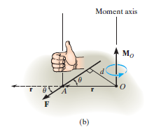
The magnitude of the cross product is defined as MO = rFsin where the angle
  is measured between the tails of r and F. To establish this angle, r must be treated as a sliding vector so that
  can be constructed properly. Since the moment arm d = rsin
 therefore,
MO = rFsin
MO = Fd
Cartesian Vector Formulation: If we establish x, y, z coordinate axes, then the position vector r and force F can be expressed as Cartesian vectors, Fig. (a) below.

Formulating the equation in matrix format we have,

Where,
rx, ry, rz represent the x, y, z components of the position vector drawn from point O to any point on the line of action of the force.
Fx, Fy, Fz represent the x, y, z components of the force vector.
If the determinant is expanded, we will get the value of MO as,
MO = (ryFz – rzFy)i – (rxFz – rzFx)j + (rxFy – ryFx)k
Moment of a Force about a Specified Axis:

Sometimes, the moment produced by a force about a specified axis must be determined. For example, suppose the lug nut at O on the car tire in Fig. above needs to be loosened. The force applied to the wrench will create a tendency for the wrench and the nut to rotate about the moment axis passing through O; however, the nut can only rotate about the y axis. Therefore, to determine the turning effect, only the y component of the moment is needed, and the total moment produced is not important. To determine this component, we can use either a scalar or vector analysis.
Scalar Analysis. To use a scalar analysis in the case of the lug nut in Fig. above, the moment arm perpendicular distance from the axis to the line of action of the force is dy = d cos  . Thus, the moment will be
MOy = F(d cos )
)
Vector Analysis: To find the moment of force F in above figure about the y axis using a vector analysis, we must first determine the moment of the force about any point O on the y axis by applying MO = r x F. The component My along the y axis is the projection of MO onto the y axis. It can be found using the dot product discussed above, so that My = j*MO = j*(r x F) where j is the unit vector for the y axis.
We can generalize this approach by letting ua be the unit vector that specifies the direction of the axis shown in Fig. 4–21. Then the moment of F about the axis is

This combination is referred to as the scalar triple product. If the vectors are written in Cartesian form, we have


Equivalent Force:
As discussed above, the equivalent force can be calculated using two methods, either by Analytical method like simple laws of vector addition, subtraction or Parallelogram law of vector addition or Method of Resolution.
e.g.1: Two forces of 100 N and 150 N are acting simultaneously at a point. What is the resultant of these two forces, if the angle between them is 45°?
Solution:
Here, the two forces are First force (F1) = 100 N; Second force (F2) = 150 N and angle between F1 and F2 (θ) = 45°.
We know that using parallelogram law of vector addition, we get,


R = 232 N.
In this way, we can calculate the resultant between two force vectors.
e.g.2: Two forces act at an angle of 120°. The bigger force is of 40 N and the resultant is perpendicular to the smaller one. Find the smaller force.
Solution:
In this problem, one of the forces is given as 40 N and the angle between the two forces is given as 1200, as depicted in fig below. Also, the angle between the resultant and smaller force is given as 900. Thus, the resultant parallelogram is shown below.
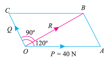
Angle between the forces ∠AOC = 120°, Bigger force (F1) = 40 N and angle between the resultant and F2 (∠BOC ) = 90° ;
Let F2 = Smaller force in N
From the geometry of the figure, we find that ∠AOB,
α = 120° – 90° = 30°
We know that

Now,
By putting the values as,
α = 300
 = 1200
F1 = 40 N, we get,


Thus,
F2 = 20 N
In this way, we can calculate the unknown quantities by analytical method of force resolution.
Now, we will understand the procedure of finding the resultant or unknown quantity using the method of resolution of forces vertically and horizontally, as discussed earlier.
e.g. 3: A machine component 1.5 m long and weight 1000 N is supported by two ropes AB and CD as shown in Fig. given below. Calculate the tensions T1 and T2 in the ropes AB and CD.

Solution:
Given: Here, weight of the component is 1000 N. Thus, for solving this example we will resolve the forces vertically as well as horizontally. Initially we will resolve the forces horizontally. As the component is in equilibrium horizontally, (i.e. along BC) we will get:
T1 cos 60° = T2 cos 45°
Thus, T1 = 1.414 T2
Now, we will resolve the tension and self-weight vertically, we will get,
T1 sin 60° + T2 sin 45° = 1000
(1.414 T2) 0.866 + T2 × 0.707 = 1000
1.93 T2 = 1000
Thus, T2 = 518.1 N
Therefore, T1 = 1.414*518.1
T1 = 732.6 N.
In this way, using the resolution of forces vertically and horizontally, we can get the required quantities.
If we wanted to find the equivalent force of many forces acting on a body, we can use the resolution of forces method. It can be explained using the example below.
e.g. 4: The forces 20 N, 30 N, 40 N, 50 N and 60 N are acting at one of the angular points of a regular hexagon, towards the other five angular points, taken in order. Find the magnitude and direction of the resultant force.

Solution:
The system of forces is as shown in the fig. above. So, for finding the equivalent force, we will resolve the forces horizontally and vertically, and then calculate the resultant force.
Now, resolve the above-mentioned force system horizontally, (i.e. Along AB) we will get,
ΣH = 20 cos 0° + 30 cos 30° + 40 cos 60° + 50 cos 90° + 60 cos 120° N
= (20 × 1) + (30 × 0.866) + (40 × 0.5) + (50 × 0) + 60 (– 0.5) N
= 36 N
Also, resolving the force system vertically, we get,
ΣV = 20 sin 0° + 30 sin 30° + 40 sin 60° + 50 sin 90° + 60 sin 120° N
= (20 × 0) + (30 × 0.5) + (40 × 0.866) + (50 × 1) + (60 × 0.866) N
= 151.6 N
Now, for calculating the magnitude of resultant force of this system,


R = 155.8 N
For finding the direction of resultant force vector,
Let, θ = Angle, which the resultant force makes with the horizontal (i.e., AB).
We will use the formula,


Thus, θ = 76.6°
In this way, using the resolution of forces method, we can find the equivalent force of the system.
Equivalent Moment:
The equivalent moment acting on a system of forces can be calculated as illustrated in the following examples:
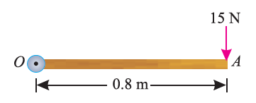
e.g. 5: A force of 15 N is applied perpendicular to the edge of a door 0.8 m wide as shown in Fig. below. Find the moment of the force about the hinge.
Solution:
Given: Force applied (P) = 15 N and width of the door (l) = 0.8 m
Moment when the force acts perpendicular to the door as shown in fig.
We know that the moment of the force about the hinge is given as,
MO = P × l = 15 × 0.8 = 12.0 N-m
If the force is to be applied at a particular angle according to fig. below,
Then the calculations are done in following procedure.
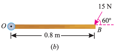
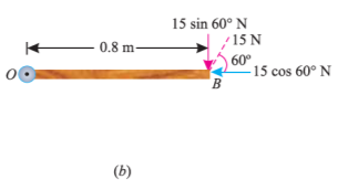
As the force applied in the question above is inclined at an angle of 600 with the horizontal, we can calculate the moment of force by two methods, either by finding out the perpendicular distance between the hinge and the line of action of the force as shown in Fig. (a) or by finding out the vertical component of the force as shown in Fig. (b) below.

From the geometry of Fig. (a), we find that the perpendicular distance between the line of action of the force and hinge,
OC = OB sin 60° = 0.8 × 0.866 = 0.693 m
∴ Moment = 15 × 0.693 = 10.4 N-m
In the second case, we know that the vertical component of the force
= 15 sin 60° = 15 × 0.866 = 13.0 N
∴ Moment = 13 × 0.8 = 10.4 N-m