UNIT 3
Friction
When the two objects slide over each other the force which opposes this type of motion is called as Friction. This force always act tangentially to the surface and its direction is opposite to that of the motion of bodies.
Coulomb friction is also known as Dry friction and was named after C. A. Coulomb who extensively studied this phenomenon. Dry friction is considered to exist between the two surfaces of objects which are in contact when there is absence of any kind of fluid lubrication.
Dry friction may take place either due to adhesion between the surfaces, or roughness or contamination of surfaces taking place.
As there is loss of mechanical energy in the form of heat during the frictional process, it turns out to be non-conservative force that is path dependent.
The force of friction is always applied in a manner that opposes the movement created within the two surfaces. Any object moving on a road or any surface slows down and then eventually stops.
Dry friction is can be further classified into static friction which is between non-moving surfaces, and kinetic friction which is between moving surfaces.
The laws are discussed as:
Laws of Static Friction:
Following are the laws of static friction:
1. The force of friction always act in direction which is opposite to motion of body.
2. The magnitude of force of friction is equal to the force acting on the body externally.
3. There is constant ratio between limiting frictional force and the normal reaction forces. Mathematically:
(F/R) = Constant
where F = Limiting friction, and R = Normal reaction.
4. The force of friction does not depend on the area of contact between the two surfaces.
5. There is dependency of frictional force on roughness of the surfaces.
Laws of Kinematic or Dynamic Friction:
Following are the laws of kinetic or dynamic friction:
1. The force of friction always act such that it opposes the motion of body.
2. There is a constant ratio between kinetic motion and normal reaction. But this ratio is slightly less when it comes to limiting friction.
3. For medium speeds, the force due to friction stays constant. But it decreases somewhat when the speed increases.
e.g. 1: The uniform crate shown in Fig. below has a mass of 20 kg. If a force P = 80 N is applied to the crate, determine if it remains in equilibrium. The coefficient of static friction is  = 0.3.
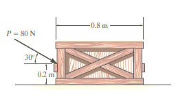
Solution:
The first step is free-body diagram i.e.
Free-Body Diagram. As shown in Fig. diagram below, the resultant normal force NC acts at a distance of x from the centre line of crate for countering the tilting effect caused by P. Hence, there are three unknowns, F, NC and x, which can be solved by equations of equilibrium.
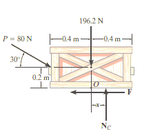
Equations of equilibrium:
Σ Fx = 0
80 cos 30° N - F = 0
Σ Fy = 0
-80 sin 30° N + NC - 196.2 N = 0
Σ M = 0
80 sin 30° N10.4 m2 - 80 cos 30° N10.2 m2 + NC (x) = 0
Thus, solving the above equations, we get,
F = 69.3 N
NC = 236 N
x = -0.00908 m = -9.08 mm
As value of x is negative, hence it acts to left of centre line of the crate. There will be no tipping since x < 0.4 m. Fmax =  Nc = 0.3(236 N) = 70.8 N. Since F that we got is 69.3 N < 70.8 N, the crate will not slip.
If a rigid body is in equilibrium when it is subjected to a system of forces that includes the effect of friction, so there is need that the system of forces should satisfy all the laws as well as equilibrium equations.
Types of Friction Problems: Generally, three types of problems are present related to dry friction. They can easily be classified once free-body diagrams are drawn and the total number of unknowns are identified and compared with the total number of available equilibrium equations.
No Apparent Impending Motion:
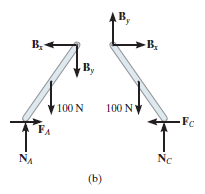
Problems in this category are strictly equilibrium problems, which require the number of unknowns to be equal to the number of available equilibrium equations. Once the frictional forces are determined from the solution, however, their numerical values must be checked to be certain that they satisfy the inequality equation i.e. F  µS N else, slipping will take place and then the body will not remain in equilibrium. A problem of this type is shown in Fig. (a). Here we have to find out the frictional forces at points A and C to confirm whether the two-frame structure will stay in equilibrium or not. If the bars are uniform and have known weights of 100 N each, then the free-body diagrams are as shown in Fig. (b). As seen from the figure there will be six force components that can also be determined by solving six equilibrium equations. Once FA, NA, FC and NC are determined, then the bars will remain in equilibrium provided
  and
and  are satisfied.

Impending Motion at All Points of Contact:
In this case the total number of unknowns will equal the total number of available equilibrium equations plus the total number of available frictional
equations,  .When motion is impending at the contact points, then
  and when the body slips, then
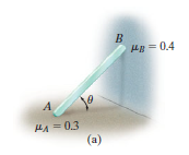
  As an e.g., let’s consider the problem to find the smallest angle
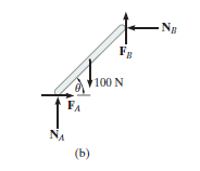
  at which the 100-N bar in Fig. below (a) can be placed against the wall without slipping.
The free-body diagram is shown below (b). From the diagram, it is found that there are 5 unknowns which have to be found out from the three equilibrium equations and the remaining two from the static frictional equations which are present at both points of contact, so that FA = 0.3*NA and FB = 0.4*NB.
Impending Motion at Few Points of Contact.
Available equilibrium equations will be more than the unknowns present. Hence, there are numerous possibilities for motion. For example, consider the two-member frame in Fig. (a) below. Here we have to find the horizontal force that is needed to create some movement. If each member has a weight of 100 N, then the free-body diagrams are as shown in Fig. (b).
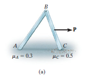
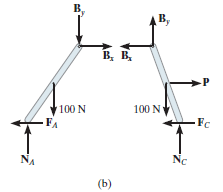
There are seven unknowns. For a single solution there is need to fulfil the six equations of equilibrium and just one of two likely static frictional equations. This means that as P increases it will either cause slipping at A and no slipping at C, so that FA = 0.3NA and  ; or slipping occurs at C and no slipping at A, in which case FC = 0.5NC and
  The actual situation can be determined by calculating P for each case and then choosing the case for which P is smaller. If in both cases the same value for P is calculated, which in practice would be highly improbable, then slipping at both points occurs simultaneously.
Thus, for solving problems related to dry friction, we follow the steps mentioned below.
Free-Body Diagrams:
Draw the necessary free-body diagrams, and unless it is stated in the problem that impending motion or slipping occurs, always show the frictional forces as unknowns (i.e., do not assume  ).
).
Initially find the number of unknowns and then compare with the available equations of equilibrium.
If unknowns are more than equations available, then frictional equation is also considered.
If the equation  is to be used, it will be necessary to show F acting in the correct sense of direction on the free-body diagram.
Equations of Equilibrium and Force of Friction.
Apply the equations of equilibrium and the necessary frictional equations (or conditional equations if tipping is possible) and solve for the unknowns.
Cartesian Vectors can be used if there is three-dimensional figure and it becomes difficult to solve it.
e.g. 2: A body of weight 300 N is lying on a rough horizontal plane having a coefficient of friction as 0.3. Determine the magnitude of the force, which is needed to move the body, acting at 25° by the horizontal.
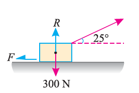
Solution:
Given:
Weight of the body (W) = 300 N; Coefficient of friction (μ) = 0.3 and
angle made by the force with the horizontal (α) = 25°
Let P = Magnitude of the force, which can move the body, and
F = Force of friction.
Initially, we will solve the problem in horizontal direction as,

The next step is to resolve the force in vertical direction, we get,


The force of friction (F) is given as,


Hence, P = 87.1 N.
e.g. 3: A body, which is positioned on a rough horizontal plane, needs a pull of 180 N inclined at 30° to the plane just for moving. Also, it was found that a push of 220 N which is inclined at 30° to the plane also moved the body. Find out the weight of the body and the coefficient of friction present here.

Solution:
Given: Pull = 180 N; Push = 220 N and angle at which force is inclined with horizontal plane (α) = 30°
Let W = Weight of the body
R = Normal reaction, and
μ = Coefficient of friction.
First of all, consider a pull of 180 N acting on the body. We know that in this case, the force of friction (F1) will act towards left as shown in Fig. (a).
Resolving the forces horizontally,
F1 = 180 cos 30° = 180 × 0.866 = 155.9 N
and now resolving the forces vertically,
R1 = W – 180 sin 30° = W – 180 × 0.5 = W – 90 N
We know that the force of friction (F1),
155.9 = μR1 = μ (W – 90)
Now consider a push of 220 N acting on the body. We know that in this case, the force of friction (F2) will act towards right as shown in Fig. (b).
Resolving the forces horizontally,
F2 = 220 cos 30° = 220 × 0.866 = 190.5 N
and now resolving the forces horizontally,
R2 = W + 220 sin 30° = W + 220 × 0.5 = W + 110 N
We know that the force of friction (F2),
190.5 = μ.R2 = μ (W + 110) ...(ii)
Dividing equation (i) by (ii)
155.9 W + 17 149 = 190.5 W – 17 145
34.6 W = 34 294
W = 991.2 N
Now substituting the value of W in equation (i),
155.9 = μ (991.2 – 90) = 901.2 μ
μ = 0.173
In this way, numericals based on dry friction can be solved.
In most cases screws are used as fasteners; however, in many types of machines they are incorporated to transmit power or motion from one part of the machine to another. A square threaded type of screw can be used when large amount of forces is to be transmitted along the axis of the screw. In this section we will analyse the forces acting on square-threaded screws. The analysis of other types of screws, such as the V-thread, is based on these same principles.
For the purpose of analysis, a square threaded screw, as in Fig. below, can be considered a cylinder having an inclined square ridge or thread wrapped around it. If we unwind the thread by one revolution, as shown in Fig., the slope or the lead angle  is determined from
  = tan-1(l/2πr). Here l and 2πr are the vertical and horizontal distances between A and B, where r is the mean radius of the thread. The distance l is called the lead of the screw and it is equivalent to the distance the screw advances when it turns one revolution.
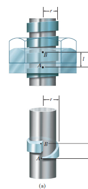
Upward Impending Motion: Let us now consider the case of a square-threaded screw that is subjected to upward impending motion caused by the applied torsional moment M, Fig. below. A free-body diagram of the entire unravelled thread can be represented as a block as shown in Fig. above. The force W is the vertical force acting on the thread or the axial force applied to the shaft, Fig. below, and M/r is the resultant horizontal force produced by the couple moment M about the axis of the shaft. The reaction R of the groove on the thread, has both frictional and normal components, where  . The angle of static friction is
  = tan-1(F/N) = tan-1
 . Applying the force equations of equilibrium along the horizontal and vertical axes, we have
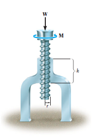

Σ Fx = 0
M/r - R sin ( +
+  ) = 0
) = 0
Σ Fy = 0
R cos ( +
+  ) - W = 0
Eliminating R from these equations, we obtain
M = rW tan ( +
+  )
)
Self-Locking Screw: A screw is said to be self-locking if it remains in place under any axial load W when the moment M is removed. For this to occur, the direction of the frictional force must be reversed so that R acts on the other side of N. Here the angle of static friction  becomes greater than or equal to
  , If
, If  then R will act vertically to balance W, and the screw will be on the verge of winding downward.
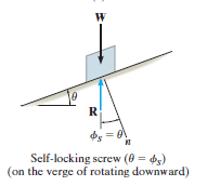
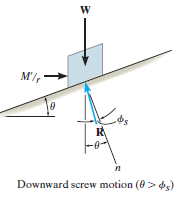
Downward Impending Motion: ( If a screw is selflocking, a couple moment M’ must be applied to the screw in the opposite direction to wind the screw downward
  .This causes a reverse horizontal force M’/r that pushes the thread down as indicated in Fig. below. Using the same procedure as before, we obtain
M’ = rW tan ( )
)
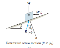
Downward Impending Motion:  . If the screw is not self-locking, then there is need for applying a moment M” for preventing the screw from winding downward. Here, a horizontal force M”/r is required to push against the thread to prevent it from sliding down the plane, Fig. below. Thus, the magnitude of the moment M” required to prevent this unwinding is
M– = Wr tan ( )
)
The principle of virtual work was proposed by the Swiss mathematician Jean Bernoulli in the eighteenth century. It provides an alternative method for solving problems involving the equilibrium of a particle, a rigid body, or a system of connected rigid bodies.
Definition:
The definitions of the work of a force and a couple can be presented in terms of the actual movements which are expressed by differential displacements having values of  and
and  . Consider now an imaginary or virtual movement of a body in static equilibrium, which indicates a displacement or rotation that is assumed and does not actually exist. These movements are first-order differential quantities and will be denoted by the symbols
  and
and  (delta r and delta
  ), respectively. The virtual work done by a force having a virtual displacement
  is
is

Similarly, when a couple undergoes a virtual rotation  in the plane of the couple forces, the virtual work is

According to the principle of virtual work if a body is in equilibrium, then virtual displacement of the body is zero for all the algebraic sum of the virtual work which is done by all the forces and moments of couple that are acting on the body. Thus,

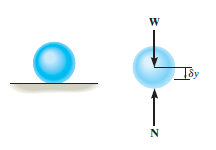
For example, consider the free-body diagram of the particle (ball) that rests on the floor, Fig. below. If we “imagine” the ball to be displaced downwards a virtual amount  then the weight does positive virtual work
  , and the normal force does negative virtual work
  , For equilibrium the total virtual work must be zero, so that

As seen from the above example, no added advantage is gained by solving particle and rigid-body equilibrium problems using the principle of virtual work. This is because for each application of the virtual-work equation, the virtual displacement, common to every term, factors out, leaving an equation that could have been obtained in a more direct manner by simply applying an equation of equilibrium.
Stability:
The potential function V of a system can also be used to investigate the stability of the equilibrium configuration, which is classified as stable, neutral, or unstable.
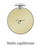
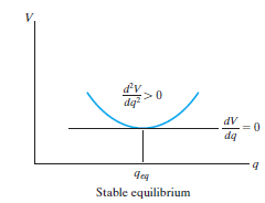
Stable Equilibrium: A system is said to be stable if a system has a tendency to return to its original position when a small displacement is given to the system. The potential energy of the system in this case is at its minimum. A simple example is shown in Fig. below. When the disk is given a small displacement, its centre of gravity G will always move (rotate) back to its equilibrium position, which is at the lowest point of its path. This is where the potential energy of the disk is at its minimum.
The graph represents stable equilibrium for one degree of freedom system.
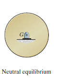
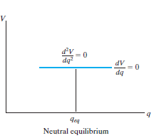
Neutral Equilibrium. A system is said to be in neutral equilibrium if the system still remains in equilibrium when the system is given a small displacement away from its original position. In this case, the potential energy of the system is constant. Neutral equilibrium is shown in Fig. below, where a disk is pinned at G. Each time the disk is rotated, a new equilibrium position is established and the potential energy remains unchanged.
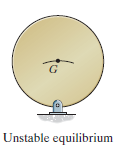
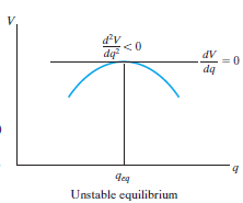
Unstable Equilibrium: A system is said to be unstable if it has a tendency to be displaced further away from its original equilibrium position when it is given a small displacement. The potential energy of the system in this case is a maximum. An unstable equilibrium position of the disk is shown in Fig. below. Here the disk will rotate away from its equilibrium position when its centre of gravity is slightly displaced. At this highest point, its potential energy is at a maximum.
