Unit - 4
Concept of Boundary layer
Boundary layer is the thickness of that layer next to a surface in which the velocity grows from zero to a maximum value (or so close to a maximum as to be of no practical difference). This thickness is usually given the symbol  (small delta).
The boundary layer, once established may have a constant thickness but, for example, when a flow meets the leading edge of a surface, the boundary layer will grow as shown in figure below.

Figure 1: Boundary layer
Boundary layer is defined as:
- The boundary layer of a flowing fluid is the thin layer close to the wall.
- In a flow field, viscous stresses are very prominent within this layer.
- Although the layer is thin, it is very important to know the details of flowwithin it.
- The main-flow velocity within this layer tends to zero while approachingthe wall (no-slip condition).
- Also, the gradient of this velocity component in a direction normal to the surface is large as compared to the gradient in the stream wise direction.
Boundary Layer Thickness, δ Boundary layer thickness is defined as that distance from the surface where the local velocity equals 99% of the free stream velocity.
δ = y(u=0.99Us)
Thickness of Boundary Layer in A Laminar Flow:
It has been experimentally found, that the thickness of the boundary layer is zero at the leading-edge, and increases to the trailing edge, the flow is laminar.
Thickness of Boundary Layer in a Turbulent Flow:
As the boundary layer continuous further downstream, it expands and the transition flow changes into turbulent flow and the transition boundary layer changes into turbulent boundary layer, which continuous over the remaining length of the plate.
According to Prandtl-Blassious, 
Some other definitions of Boundary layer Thickness:
Many other definitions of boundary layer thickness have been introduced at different times and provide important concepts based on mathematical calculations and logic These definitions are:
- Displacement Thickness (δ*)
- Momentum Thickness (θ)
- Energy Thickness (δe)
Key Takeaways:
- The boundary layer of a flowing fluid is the thin layer close to the wall.
- In a flow field, viscous stresses are very prominent within this layer.
The flow rate within a boundary layer is less than that for a uniform flow of velocity u1. The reduction in flow is equal to the area under the curve in figure given below. If we had a uniform flow equal to that in the boundary layer, the surface would have to be displaced a distance  * inorder to produce the reduction. This distance is called the displacement thickness and it is given by:

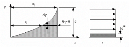
Another interpretation of the displacement thickness is that because the volumetric flow in the boundary layer is actually  the same flow would be achieved if the wall was displaced upward into the flow in an amount
  since the definition can be written in the form

Key Takeaways:

It is the distance measured perpendicular to the solid boundary, by which boundary will be displaced to compensate for the reduction in momentum of the flowing fluid due to boundary layer formation.
Momentum Thickness, θ Momentum thickness is the distance that, when multiplied by the square of the free stream velocity, equals the integral of the momentum defect. Alternatively, the total loss of momentum flux is equivalent to the removal of momentum through a distance θ. It is a theoretical length scale to quantify the effects of fluid viscosity near a physical boundary.
Momentum of fluid/sec = (mass/sec) X velocity
= (ƍ.u .dy) u
= ƍ .u2 .b. Dy
Momentum thickness is given by:

The momentum in a flow with a boundary layer present is less than that in a uniform flow of the same thickness. The momentum in a uniform layer at velocity  and height h is
  h
h . When a boundary layerexists, this is reduced by
  . Where
  is the thickness of the uniform layer that contains the equivalent to the reduction.
If density is constant, this simplifies to

Key Takeaways:

Required formula for momentum thickness
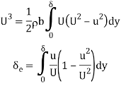
Energy thickness (δe) is defined as the thickness of an imaginary layer in free stream flow which has energy equal to the deficiency of energy caused to actual mass flowing inside the boundary layer.
By equating the energy transport rate for velocity defect to that for ideal fluid

If density is constant, this simplifies to

Kinetic energy of fluid, if plate is placed = ½ m V2 = (ρ u b dy) u2
Kinetic energy of fluid if no plate is placed = ½ m V2 = (ρ u b dy) U2
Loss of Kinetic energy = ½ ρ u b (U2 - u2) dy
Total loss of Kinetic energy in BC
= 1/2 ρ u b ∫ ( U2 - u2) dy
Loss of Kinetic energy through ( ) of fluid flowing with velocity U.
= ½ mass x velocity2 = ½ (ρ b δe U) U3
= ½ (ρ b δe) u2
Equating Equations
1/2 ρ b δe

Key Takeaways:
It is the distance perpendicular to solid boundary, by which the boundary should be displaced to compensate for the reduction in kinetic energy of the flowing fluid in the formation of boundary layers.
BOUNDARY LAYERS IN PRESSURE GRADIENTS
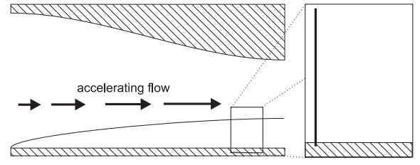
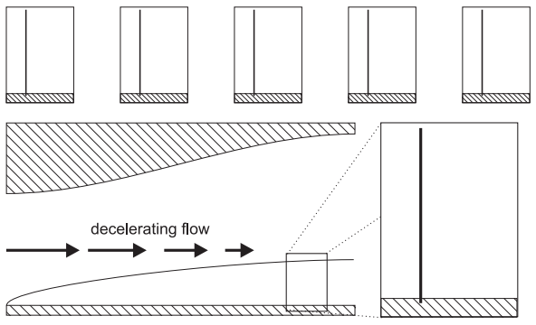
If the free stream is accelerating, then there must be a pressure gradient pushing the flow in the same direction as the free stream. This is similar to combined Couette/Poiseuille flow with a favourable pressure gradient. The velocity gradient at the wall becomes steeper: If the free stream is decelerating, then there must be a pressure gradient pushing the flow in the opposite direction to the free stream. This is similar to combined Couette/Poiseuille flow with an adverse pressure gradient. The velocity gradient at the wall becomes less steep and the flow can even reverse.
BOUNDARY LAYER SEPARATION
The streamlines and pressure field of the inviscid flow around an ellipse are shown below. There are high pressure regions around the front and rear stagnation points.
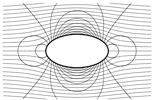
Viscous fluids obey the no slip condition. This means that a thin boundary layer forms around the surface of the ellipse, growing as the fluid moves from the front to the back. We will imagine for the moment that the boundary layer sticks to the surface all the way to the back of the ellipse.
Around the front of the ellipse there is a favourable pressure gradient - i.e. the pressure is pushing in the same direction as the bulk fluid motion. The favourable pressure gradient makes the velocity gradient at the wall steeper. Around the back of the ellipse there is an adverse pressure gradient - i.e. the pressure is pushing in the opposite direction to the bulk fluid motion. The adverse pressure gradient makes the velocity gradient at the wall less steep and, unless the fluid is extremely viscous, eventually will cause flow reversal.
DELAYING BOUNDARY LAYER SEPARATION
Separation occurs when flow reversal occurs. From our Couette/Poiseuille flow model we know that there is a competition between the adverse pressure gradient, which pushes the flow backwards, and the rate of momentum diffusion through the fluid, which pushes the flow forwards. We can increase the rate of momentum diffusion by increasing the viscosity. This delays separation:
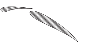
In aerodynamics, separation is usually undesirable because it increases drag, as we will see in chapter 8. It is usually impossible to change the fluid’s viscosity but it is possible to delay separation in other ways, for example by injecting the momentum from the free stream flow directly into a boundary layer.

References:
- Frank M. White, Fluid mechanics, Tata McGraw Hills.
- Som and Biswas, Fluid mechanics and machinery.
- Various presentations and pdf from different websites.