Unit-4
Control Systems
4.1.1 Basic elements
Control system is system can be used for
Feedback
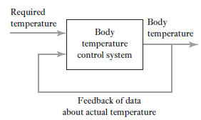
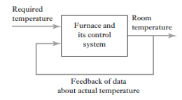
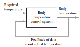
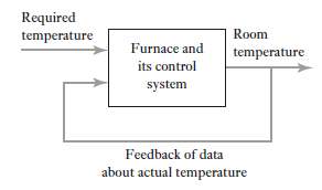
We all know our body tries to maintain temperature constant whether its summer or winter. To maintain body temperature at constant our body have some control system (Figure 1). If temperature is hot our body start to sweat and if it’s cold out there, we shiver. Both these mechanisms are used to maintain our body temperature at some constant level. Now consider a room temperature control system which maintaining the room temperature at some constant temperature (figure 2). The control system has an input which senses the room temperature and compares this temperature with required room temperature and provides appropriate response in order to obtain the required temperature. This is an example of feedback control. In feedback control system signals from output are fed back to comparator in order to control the required output.
|
Figure 1: Feedback control system of human body
|
Figure 2: Room temperature control system
4.1.2 Open/Closed Loop
Open and closed loop systems
In open loop control system, no information on current situation is fed back to element to adjust and maintain the required condition. Consider an example of room heater which have selection switch which allows a 1 kW or a 2 kW heating element to be selected. If a person in room select 1kW switch to heat up the room. If room’s door or window open up then it is impossible to maintain room temperature at required condition. This is an example of open loop control system (Figure 3A) where no information fed back to the element to adjust it and maintain a constant temperature. Now consider a room heater with thermometer to check room temperature regularly and switches the 1kW to 2kW elements on or off, according to difference between actual and required room temperature to maintain it at required level. This is the example of closed loop control system (Figure 3B) in which information is fed back to input system being adjusted according to whether its output is at required level.
|
Figure 3: Room heater system
A: Open-loop system
B: Closed-loop system
Open-loop system | Closed-loop system | ||
|
| ||
|
| ||
|
| ||
|
|
Basic elements of open-loop system
Open loop systems have three basic elements (figure 4) discussed as below.
Control element: This element determines what action to be taken as a result of the input of the required value signal to the system.
Correction element: This element has input from the control element and gives an output of some action designed to change the variable being controlled.
Process: This is the process of which a variable is being controlled.
|
Figure 4: Basic element of control system
Basic element of closed-loop system
Function of each element of closed-loop system (Figure 5) is discuss below
Comparison element: The function of this element is to compare required value of variable being controlled with measured value and produces an error signal.
Error = measured value – required value
Thus, if there is a difference between the required value and the measured values of the variable only then there will be an error signal and so required control action is taken.
Control unit: This element decides what action are needs to take when receives an error signal. Control plans are used by element to control process e.g. signal which switches on or off when there is an error. Control plan is permanently fixed by the way the elements are connected together known as hard-wired system. Sometimes control plan is programmable systems where the control plan is stored within a memory unit and may be altered by reprogramming it.
Correction unit: The correction element takes an action in the process to correct or change the controlled condition. For example: A switch which switches on a heater and so increases the temperature of the process The term actuator is used for the element of a correction unit that provides the power to carry out the control action.
Process element: The process is what is being controlled. It could be a room in a house with its temperature being controlled or a tank of water with its level being controlled.
Measurement element: This element produces a signal as per required variable condition. For example: a switch which is switched on when a particular position is reached.
|
Figure 5: Elements of closed loop system.
4.1.3 Design of block diagram
Block diagram: Pictorial representation of function performed by each component of system and that of flow of signals.
|
Figure 6: Single block diagram representation
Where,
X(s)=input function of s Y(s)= output function of s G(s)= transfer function as the operator in the box that converts the input to the output. Overall transfer function of any control system consists of series of connected elements and system with feedback loops. |
Systems in series
Consider a system consisting of two subsystems in series as shown in figure 7.
|
Figure 7: Systems in series
From figure 12 X(s) is input to first subsystem and output is Transfer function of first subsystem is
Second subsystem has Transfer function of second subsystem is
Overall transfer function for system is
|
Thus, we can say that overall transfer function of system is product of transfer function of individual series elements.
Systems with feedback
System with negative feedback
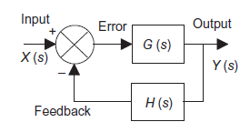
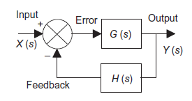
Consider a system with negative feedback loop as shown in figure 8. Where the output Y(s)is fed back via a system with a transfer function H(s) to subtract from the input X(s) to the system having G(s) as transfer function
|
Figure 8: System with negative feedback.
Input for feedback system is Y(s) and output is H(s)Y(s). The error is the difference between the system input signal X(s) and the feedback signal H(s)Y(s) Error= X(s)-H(s)Y(s) |
This error is input to system G(s) and output is Y(s)
|
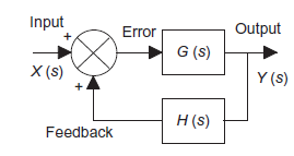
System with positive feedback
|
Figure 9: System with positive feedback
Error= X(s)+H(s)Y(s) This error is input to system G(s) and output is Y(s)
|
Block manipulation
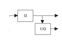
Complex systems have many elements and sometimes more than one input. Following are some ways to reorganise the blocks in simplified way and still give the same overall transfer function for given system.
| System | Equivalent system |
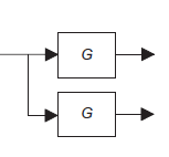
Blocks in series |
|
|
Moving a take-off point to beyond a block |
|
|
Moving a take-off point to ahead of a block |
|
|
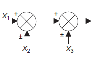
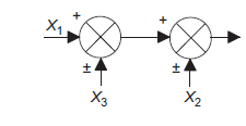
Rearrangement of summing points |
|
|
Interchange of summing points. |
|
|
Moving a summing point ahead of a block. |
|
|
Moving a summing point beyond a block |
|
|
Removing a block from a feedback path |
|
|
Removing a block from a forward path. |
|
|
Automatic controllers
Automatic controller is to compare actual value of output to desired value of output, determines the deviation and produces a signal which will reduce the deviation to zero or to very small value.
Automatic control produces a control signal is known as control action. Control action may operate through mechanical, pneumatics, hydraulic or electric means.
Controller is device which maintains a process variable value at set point (it is value should be at or near some reference value).
Classification of control action
i) Discontinuous type “ON-OFF”
ii) Continuous type
(1) Proportional
(2) Derivative
(3) Composite
(a) Proportional + integral
(b) Proportional + derivative
(c) Proportional + derivative + integral
Basic function controller
ON-OFF controller
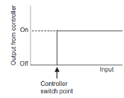
ON-OFF controller is simplest type of controller. Also known as two position controllers. This type of control system is commonly used in domestic system. For example: Heating system, refrigerator etc.
ON-OFF controller keeps measured value within maximum or minimum value depending upon the controlled variable, whether it is greater or less than the set point.
|
Figure 10: ON-OFF control
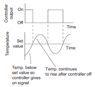
Consider a room heating application whose ON-OFF control is shown in figure 11.
|
Figure 11: Fluctuation of temperature about set value
A precise ON-OFF controller will ON when measured value is below set point and controller will be OFF if measured value is above set point. But in actual practice ON-OFF will not work exactly at set point. This is due to transfer or process lag or dead time of instrument. The difference between maximum and minimum level of variable where controller output does not change even ON-OFF is essential is known as dead zone also known as differential gap.
ON-OFF control is suitable for following conditions
Advantage of ON-OFF controller
Disadvantage of ON-OFF controller
Applications of ON-OFF controller
4.2.1 Proportional controller (P)
Proportional control is continuous action operation where output of controller is linear function of error signal i.e. output changes with proportional change of input.
Mathematically
Where
Constant
Controlling the level of water in a cistern using float method is an example of the use of a proportional controller, lever is used to determine the control mode (Figure 12) |
|
Figure 12: The float-lever proportional controller
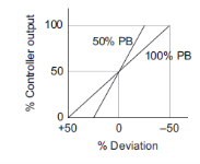
On controller there is setting for  instead of there is setting for proportional band (PB). Mathematically PB = (1/
 )*100%
If PB is high then  is low i.e. controller is less sensitive or gain decreases causing good control action. On the other hand, if PB is low then sensitivity is increases causing output change in large steps.
The proportional action is comparatively very fast and control variable settles down close to set point with time. The main drawback of P control method is offset i.e. difference between set point and measured value after measured variable is settles down. And this drawback is permanent feature of proportional control and cannot remove d as it.
|
Figure 13: Proportional action
Advantages of proportional controller
Disadvantages of proportional controller
Applications of proportional controller
Integral controller
It is used as reset mode. In integral controller output changes as a rate or speed proportional to magnitude of deviations. Hence larger the deviation faster the correction is applied. If deviation is small then slower the correction is applied.
Mathematically

Where
 Controller output
 Error signal
 Gain of controller
 Integral time
If error is not output will begin to increase or decrease till controlled variable reaches exactly to set value. And if error is zero the output stays at value where error is zero.
Advantages integral controller
Disadvantages of integral controller
Derivative controller
In derivative controller output is depend on rate of change of error. Mathematically

Where
 Controller output
 Error signal
 Gain of controller
 Derivative time
When error is zero or constant output is zero that’s why this controller cannot use alone. For rate of change or error there is a unique value of controller output.
Composite control action
4.2.2 Proportional + integral control action (PI)
Proportional control action produces offset in system when load changes and this offset is eliminated by adding integral action to proportional action.
Mathematically control output is given as
Where
|
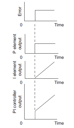
Figure 14 shows how a system with PI control reacts when there is an abrupt change to a constant error.
|
Figure 14: PI control
Let there is step in change in error signal e(t) = 1 then
|
Thus, controller output is suddenly change by an amount of  and then suddenly changes linearly
with respect to time at rate of  as shown in figure 14.
PI controller provides with two knob one adjusting gain  and other one is for adjusting integral time
  .
.
The main advantage or P+I control Is that It can remove or nullify the offset produced during p action. The integral control is also known as 'reset action' with the adjustable parameter Integral time T which is expressed in seconds or minutes.
Advantages of P+1 Controller Action:
Proportional + derivative control action (P+D)
It is also known as rate control. The derivative control never used alone, because in this mode, the output m(t) of controller is proportional to the derivative or error signal. If by chance the error signal, which may be significant, remains constant for certain amount of time, then the derivative of constant being zero, the output of controller will be zero. It means that despite the significant error, the controller is taking no corrective action just because the error has got stuck up at the constant value, in derivative control mode; the magnitude of the controller output is proportional to the rate of change of actuating error signal. The derivative control action is added to proportional control action, is called as PD control action. The governing equation for PO control action is.
Where,
Put d/dt=D
|
Advantages of (P+D) Controller Action
It Is specifically used for process controlling stow parameters such as temperature where there is already enough process lac, transfer lag and transmission lags. Without derivative control, controlling of such parameter would be too slow or delayed. This mode gives a controller output based on the rate of change of error and thus. it tins rate W high; the derivative action is Immediately in action.
4.2.3 Proportional + integral + derivative control action (PID)
For powerful and complex control action PIO control action is used. In PID control action, the output m(t) is a linear combination of Input e(t), the rate of change of input and the time Integral of Input. The control is thus additive information of proportional action, derivative action and integral action. The governing equation of P10 control action is given as,
Substitute d/dt=D and
|
PID controls are best suited for,
Servomotor mechanism
The name servomechanism describes a complete system that provides automatic control of an object or quantity as desired. Such a system may include many electrical, mechanical or hydraulic devices. By their use, person can control large power with greater speed and accuracy than that person alone can provide.
A servomechanism is a dosed loop system that moves or changes the position of the controlled object so that It will follow up or agree with the position of a control device, it Includes motor to cause such mechanical movement. For example, it may open or close valve in a hydraulic or steam or chemical process, turn a rod of Link with respect to its neighbouring link, move a transformer tap, moves up or down the control rods of nuclear reactor etc. The short term servo is commonly used to apply to any type dosed loop system. Servos are used in defence, navigation as well as in industry. They are used in industry In the automatic follow up control of precision machine tools, the remote handling of dangerous materials, automatic production lines etc. D.C. and A.C. Motors are two types of electric actuators, used in low power ratings and are known as servomotors. Servomotor mechanism is a control system that converts a small mechanical motion into one requiring much greater power; may include a negative feedback system. Since the operator cannot do repetitive and critical functions continuously and correctly due to his limitations then the automatic closed control loop has to be employed in this system which would be doing exactly similar functions continuously and endlessly. The closed loop system is also known as servo mechanism. A servomotor mechanism means simply a system which is used to control the mechanical output of position or time derivative position, such as velocity or acceleration of Input signal. Servomotor mechanism has found number of applications In Industry such as in tool position control, missile guidance system, radar tracking system etc. Actuators are used to operate the valves, heaters etc. Actuators are very important elements of servomotor mechanism. The elements of servomotor mechanism are actuators, error detectors, rollback element, amplifiers, controllers (hydraulic/pneumatic/electronic) etc. Servomotor mechanism works very eager in milliseconds. This mechanism is costlier but it is convenient because of its properly controlled fast actions.
|
Figure 15: Block diagram of servomotor mechanism
DC servomechanism
Working: Servomechanism is an automatic device for the control of a large power output by means of a small power input or for maintaining correct operating conditions in a mechanism. It is a type of feedback control system. The constant speed control system of a DC motor is a servomechanism that monitors any variations in the motor’s speed so that it is quickly and automatically returns the speed to its correct value. Some older servomotor systems use a tachometer and encoder for feedback. There are two feed backs: (I) Velocity feedback and (ii) Position feedback. Position Feedback DC Servomechanism: Servomechanism system, which controls the position of a mechanical load In accordance with the position of the reference shaft, is called D.C. Servomechanism. Load shaft is driven by motor through gear system. The driving motor is geared to the load to be moved. The motor develops a torque which Is transmitted to the output shaft through a gear train of ratio
N= Load shaft speed /Motor shaft speed
Here or denotes the output position whereas  denotes the desired or reference position. The two potentiometers convert the input and output shaft positions into proportional electrical signals, which are in turn compared by error detector and error signal equal to the difference of the two appears at the leads coming from potentiometer wiper arms. The error detector's output voltage is Ve and that is proportional to the error in angular position
 .
.
To understand the operation, Assume Kp=Potentiometer sensitivity in volts/rad = 100 volts/rad, and output shaft position be 0.5 rad, corresponding to this condition the slider arm B has a voltage of +50 volts. Let the slider arm A also set at +50 volts. Then error signal will be zero. Hence, motor has zero output torque, so that load stays stationary at 0.5 rad. Now, assume that the new desired position of load Is 0.6 rail. To achieve this, arm A is placed at +60 volts position. Attie arm 9 is at the +50-volt position. This makes an error signal of +l0 volts. Now, this error signal is amplified and fed to servomotor which generate an output torque that reposition the load. This system comes to a steady position only when error signal become zero, that is the arm El reaches the position corresponding to 0.6 red (i.e. +60 volts),
|
Figure 16: D.C. servomechanism
Applications of D.C. Servomechanism:
1. Automatic machine tools.
2. Constant tension control of sheet rolls in paper mills.
3. Control of sheet metal thickness in not rolling mills.
4. Radar tracking system.
5. Missile guidance system.
6. Satellite-tracking antennas.
4.2.4 Tuning of Controllers
While designing of controller involves selecting control modes to be used and control mode setting i.e. selecting which control action P mode, PD mode, PI mode or PID mode choose for particular situation and deciding values of . These determine how the system reacts to a disturbance or a change in the set value, how fast it will respond to changes, how long it will take to settle down after a disturbance or change to the set value, and whether there will be a steady state error.
Figure 17 shows types of response that can occur with the different modes of control when subject to a step input (input can be different constant set value or a sudden constant disturbance) P control will give a fast response with oscillations which die away to leave a steady state error. PI control has no steady state error but show more oscillations before settled down. PID control has also no steady state error, because of the integral element, and show fewer oscillations than the PI control. The inclusion of derivative control reduces the oscillations.
|
Figure 17: Responses to (A) P, (B) PI, and (C) PID control
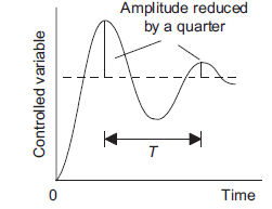
Tuning means methods used to select best controller setting to obtain a particular form of performance, e.g. where an error signal results in the controlled variable oscillating about the required value with an oscillation which decays quite rapidly so that each successive amplitude is a quarter of the preceding one. The following is a description of some of the methods used for tuning.
1) Ultimate Cycle Tuning Method
With this method, with the closed-loop system, the integral and derivative actions are first reduced to their least effective values. The proportional constant Kp is then set low and gradually increased until oscillations in the controlled variable start to occur. The critical value of the proportional constant Kpc at which this occurs is noted and the periodic time of the oscillation’s Tc measured. The procedure is thus:
1. Set the controller to manual operation and the plant near to its normal operating conditions
2. Turn off all control modes but proportional
3. Set Kp to a low value, i.e. the proportional band to a wide value
4. Switch the controller to automatic mode and then introduce a small set-point change, e.g. 5_10%
5. Observe the response
6. Set Kp to a slightly higher value, i.e. make the proportional band narrower
7. Introduce a small set-point change, e.g. 5_10%
8. Observe the response.
9. Keep on repeating 6, 7 and 8, until the response shows sustained oscillations which neither grow nor
decay. Note the value of Kp giving this condition (Kpu) and the period (Tu) of the oscillation
10. The Ziegler and Nichols recommended criteria for controller settings for a system to have quarter
amplitude decay is given by Table 1. For a PID system with some overshoot or with no overshoots,
the criteria are given by table 2.
Table 1: Settings for the Ultimate Cycle Method for Quarter Amplitude Decay
Type of controller | Kp | Ti | Td |
P | 0.5Kpu |
|
|
PI | 0.45Kpu | Tu/1.2 |
|
PID | 0.6Kpu | Tu/2 | Tu/8 |
Table 2: Settings for the Ultimate Cycle Method for PI Control
Type of controller | Kp | Ti | Td |
PID, 1/4 decay | 0.6Kpu | Tu/2 | Tu/8 |
PID, some overshoot | 0.33Kpu | Tu/2 | Tu/3 |
PID, no overshoot | 0.2Kpu | Tu/3 | Tu/2 |
2) Quarter Amplitude Decay
A variation on the ultimate cycle method involves not adjusting the control system for sustained oscillations but for oscillations which have a quarter amplitude decay (Figure 18). The controller is set to proportional only. Then, with a step input to the control system, the output is monitored and the amplitude decay determined. If the amplitude decay is less than a quarter the proportional gain is increased, if less than a quarter it is decreased. The step input is then repeated and the amplitude decay again determined. By a method of trial and error, the test input is repeated until a quarter wave amplitude decay is obtained. We then have the value for the proportional gain constant. The integral time constant is then set to be T/1.5 and the derivative time constant to T/6.
|
Figure 18: Quarter amplitude decay
3) Lambda Tuning
Lambda tuning has been developed to give a non-oscillatory response to set point changes and load disturbances. The first part of the test is to switch the controller to manual mode, wait until the process variable has settled to a steady state value and then apply an abrupt step up, a so-called bump, in the set point. The process variable is then monitored in response to this step input until it settles out again (Figure 19). The response is then specified by extracting from the response graph the dead time D, the process time constant τ, which is defined as being the lambda value, and the process gain Kp, where Kp5(the resulting change in the process variable)/(the size of the step input producing the change). The PID controller is then set to have the values:
Integral time =T Derivative time= 0 |
|
Figure 19: Response to sudden step input, i.e. a bump
4) Software Tools
Software packages are available for tuning. They gather data from the system, develop process models and then suggest optimal tuning values. An impulse can be induced in the system and then the control system’s response used to determine optimum loop values.
References:
1. Instrumentation and control systems by W. Bolton, 2nd edition, Newnes, 2000.
2. Thomas G. Beckwith, Roy D. Marangoni, John H. Lienhard V, Mechanical Measurements (6th Edition) 6th Edition, Pearson Education India, 2007.
3. Gregory K. McMillan, Process/Industrial Instruments and Controls Handbook, Fifth Edition, McGraw-Hill: New York, 1999.
