Unit– 4
Torsion, stresses and deformation in circular and hollow shafts
Torsion equation or torsion constant is defined as the geometrical property of a bar’s cross-section that is involved in the axis of the bar that has a relationship between the angle of twist and applied torque whose SI unit is m4. The torsion equation is given as follows:
T/J= τ/r=Gθ/L
Following are the assumptions made for the derivation of torsion equation:
Consider a solid circular shaft with radius R that is subjected to a torque T at one end and the other end under the same torque.
T = Maximum twisting torque or twisting moment
D = Diameter of shaft
R = Radius of shaft
J = Polar moment of Inertia
τ= Maximum Permissible Shear stress (Fixed for given material)
G = Modulus of rigidity
θ= Angle of twist (Radians) = angle D'OD L = Length of shaft.
 = Angle D'CD = Angle of Shear strain

Fig.1
Then Torsion equation is: T/J = τ/R = G. θ /L
Let the shaft is subjected to a torque or twisting moment 'T'. And hence every C.S. of this shaft will be subjected to shear stress.
Now distortion at the outer surface = DD'
Shear strain at outer surface = Distortion/Unit length tan θ = DD'/CD
i.e. shear stress at the outer surface (tan =) = DD'/L or = DD'/L ...(i)
Now DD' = R.θ or  = R .θ /L ...(ii)
Now G = Shear stress induced/shear strain produced
G = τ / (R. θ /L);
or; τ/R = G. θ /L …..(A);
This equation is called Stiffness equation.
Hear G, θ , L are constant for a given torque 'T'. That is proportional to R
If τ r be the intensity of shear stress at any layer at a distance 'r' from canter of the shaft, then;
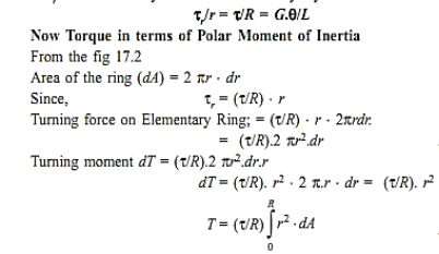
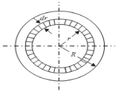
Fig.2

Now from equation (ii) T = (τ/R) J
or τ/R = T/J; ..(B)
This equation is called as strength equation
The combined equation A and B; we get
T/J = τ/R = G. θ /L
This equation is called as Torsion equation.
From the relation T/J = τ/R
We have
T = τ .J/R = τ .ZP
For the given shaft IP and R are constants and IP/R is thus constant and is called as polar modulus (ZP) of the shaft section.
Polar modulus of section is thus measure of strength of shaft in the torsion.
Torsional rigidity or Torsional Stiffness (K): = G.J/L = T/θ
Key takeaways
1) Torsional rigidity or Torsional Stiffness (K): = G.J/L = T/θ
2) Torsion equation is: T/J = τ/R = G. θ /L
Consider a bar or shaft of circular cross section twisted by a couple T, assume the left-hand end is fixed and the right-hand end will rotate a small angle ϕ, called angle of twist if every cross section has the same radius and subjected to the same torque, the angle ϕ (x) will vary linearly between ends under twisting deformation, it is assumed
1. Plane section remains plane
2. Radii remaining straight and the cross sections remaining plane and circular
3. if ϕ is small, neither the length L nor its radius will change consider an element of the bar dx, on its outer surface we choose a small element abcd,

Fig. 3
During twisting the element rotate a small angle d, the element is in a state of pure shear, and deformed into ab'c'd, its shear strain γmax is
γmax = bb’/ab = r d ϕ / dx
d ϕ / dx represents the rate of change of the angle of twist ϕ, denote θ= d ϕ / dx as the angle of twist per unit length or the rate of twist, then γmax = r θ in general, ϕ and θ are function of x, in the special case of pure torsion, θ is constant along the length (every cross section is subjected to the same torque) θ = ϕ/L and γmax = rθ/L and the shear strain inside the bar can be obtained
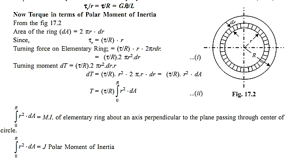
Fig. 4
γ = ρ.θ=ρ. γmax / r
γmin = r1 /r2 γmax
For a circular tube, it can be obtained. The above relationships are based only upon geometric concepts, they are valid for a circular bar of any material, elastic or inelastic, linear or nonlinear.
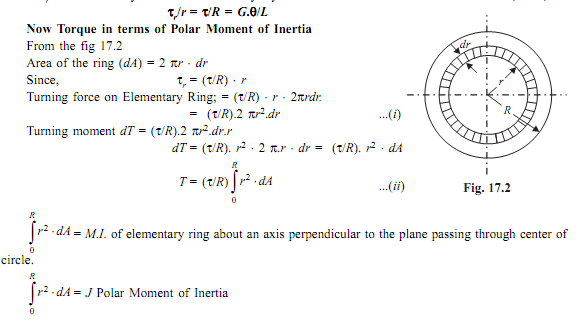
A shaft which tapers in a series of steps rather than one continuous narrowing. The stepped shaft was introduced by the True-Temper Division of The American Fork and Hoe Company which initially manufactured shafts with a smooth taper from butt to tip.

Fig. Beam Fixed at Both Ends - Single Point Load
Bending Moment
MA = - F a b2 / L2 (1a)
where
MA = moment at the fixed end A (Nm, lbf ft)
F = load (N, lbf)
MB = - F a2 b / L2 (1b)
Where,
MB = moment at the fixed end B (Nm, lbf ft)
MF = 2 F a2 b2 / L3 (1c)
Where,
MF = moment at the point load (Nm, lbf ft)
Deflection
δF = F a3 b3 / (3 L3 E I) (1d)
where,
δF = deflection at point load (m, ft)
E = Modulus of Elasticity (Pa (N/m2), N/mm2, psi)
I = Area Moment of Inertia (m4, mm4, in4)
Support Reactions
RA = F (3 a + b) b2 / L3 (1f)
where
RA = support force at fixed end A (N, lbf)
RB = F (a + 3 b) a2 / L3 (1g)
where
RB = support force at fixed end B (N, lbf)
Springs are energy absorbing units whose function is to store energy and to restore it slowly or rapidly depending on the particular application.
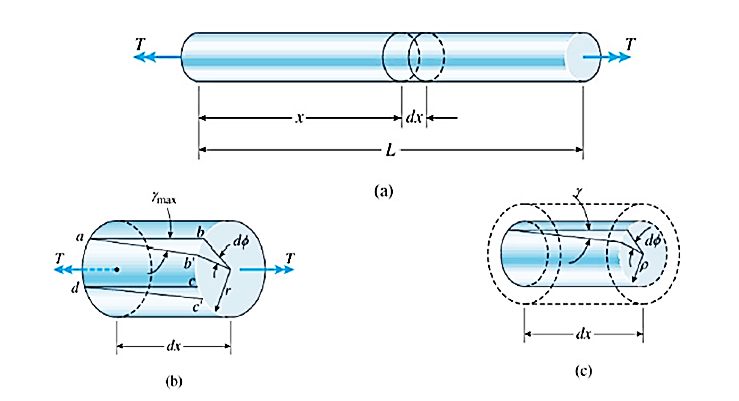
Fig. Spring
A spring may be defined as an elastic member whose primary function is to deflect or distort under the action of applied load; it recovers its original shape when load is released.
Helical spring: They are made of wire coiled into a helical form, the load being applied along the axis of the helix. In these type of springs the major stresses is torsional shear stress due to twisting. They are both used in tension and compression.
Helical springs are used in various applications due to their shock absorption and load bearing properties. So, it is important to calculate its load bearing capacity, if you are selecting a helical spring for an application. This post discusses two types of helical springs that are differentiated on the basis of their load bearing capacity.
Types of Helical Springs on the Basis of Load Bearing Capacity
The load bearing capacity depends on various factors such as total number of coils, coil gaps, wire shapes, etc. The below mentioned are the two types of helical springs distinguished on the basis of their coils.
2. Closed Coiled Helical Springs: Designed to resist stretching and twisting, these springs are also known as tension/extension springs. These springs feature an eye or a hook at the end for attachment. These springs can endure stress caused by high torsion or bending. The coils are closely wound to each other, and lie on the same axis of the helix. The turns of this spring lie at 90 degrees to the axis of the helix. These springs are used for heavy duty applications such as carburetors, garage door assemblies, vise-grip pilers, etc.
CLOSE COILED HELICAL SPRING-UNDER AXIAL FORCE
This spring is subjected to either axial load or axial couple.
The parameters to be studied in springs are stress, stiffness and resilience.
Symbols used
Do= outer coil diameter
Di= inside coil diameter
Dm= mean coil diameter = D
d=diameter of wire
na = number of active turns (circles) in the spring
ni = Number of inactive turns
C = spring index= D/d
(normally 4 to 12)
k = Wahl’s Stress concentration factor
ԏ = shear stress in spring wire
ϴ = angle of twist in wire
L= length of wire
T = torque= W x R
CLOSED COILED HELICAL SPRINGS – AXIAL LOAD

Fig. Closed coiled helical spring under axis load W
As the helix angle (angle of the turn with the horizontal) is small, axial load only causes twist in the wire of the spring. It is similar to a shaft under pure torsion. It is considered only in pure torsion and the torsion equation is used to analyze it.
Actually stresses present will be
Bending stress and direct shear stresses have been found to be negligible. However their small effect has been accounted for by Wahl stress concentration factor.
T = W x R=WxD/2
T/J = ԏ/r = Gϴ/L
J = (π/64)d4
R =radius of wire = d/2
G = Modulus of rigidity
ϴ= Angle of twist in radians
L= length of wire = 2πrn
Using T/J = ԏ /r
(WD/2)/ (π/64)d4 = ԏ /(d/2)
Α = angle of helix = 0 in a closed coil spring
Stress = ԏ= 8WD/πd3
Stress concentration factor accounts for two things
(i) Direct shear stress consideration
(ii) Stress concentration due to change in curvature
Wahl’s stress concentration factor is given by
K = (4C-1)/(4C-4)+ 0.615/C
Where C is spring index=D/d
Now actual shear stress becomes = kԏ= k 8WD/πd3
(1/2)W δ = (1/2) Tϴ,
δ = 64 WR3n/Gd4
Stiffness = k= W/δ = Gd4/64R3n
Resilience = u = ԏ2/2G
Solid length = nd
References