Unit - 1
Design of Simple Machine Elements
Factor of safety: It is defined as ratio of maximum stress to working stress
Mathematically FOS = 
For Ductile material, FOS = 
For brittle material, FOS = 
Typical values
Application | FOS |
Aircraft components | 1.5-2.5 |
Bolts | 8.5 |
Pressure vessels | 3.5-6 |
Reliable material , normal condition | 1.3-1.5 |
Ordinary material , normal condition | 2-2.5 |
Unreliable material , severe condition | 3-4 |
Importance of FOS
- There is variation in properties of material like yield strength, ultimate strength
- Uncertainty in variation of external loads and forces
- Variation in dimension of component due to lack of workmanship
- To ensure safety of component from above mentioned variation and uncertainty, Factor of Safety is useful in Design
Key Takeaway:
- FOS is important for design safer and reliable component, higher the uncertainty regarding material and external forces higher the FOS for safer Design
Selection of FOS Depends upon
- Effect of Failure: Failure of a machine component, such as a ball bearing in a gearbox, can cause only minor discomfort or time loss. However, in other circumstances, such as when a pressure vessel's valve fails, there is significant financial loss or a risk to human life.
- Type of Load: When the external force acting on the machine element is static, i.e., a load that does not change in magnitude or direction with respect to time, the factor of safety is low. When the machine element is subjected to impact load, on the other hand, a larger factor of safety is chosen. This is because the impact load is supplied rapidly to the machine component, usually at high speeds.
- Material: Yield strength is the failure criterion when the component is made of a homogenous ductile material like steel. In such instances, the safety factor is frequently modest. A cast iron component, on the other hand, has a non-homogeneous structure and is chosen with a larger factor of safety based on ultimate tensile strength.
- Reliability of Component: When Component are made defense equipment, power station high reliability is expected so FOS is high
- Cost of Component: As the factor of safety rises, so do the component's dimensions, material requirements, and cost. For low-cost machine parts, the safety factor is minimal.
- Service Condition: FOS depends upon the condition of environment in which component is going to be used. For corrosive, High temperature environment high FPS is used
- Quality of Manufacturing : When manufacturing quality is excellent, variances in machine component dimensions are minimized, and a low factor of safety can be chosen. To compensate for poor manufacturing quality, a larger factor of safety is necessary.
Under Normal conditions
Type | Limiting condition | Failure Type | FOS |
Cast Iron | UTS |
| 3 to 5 |
Ductile (Static load) | YTS | Plastic Deformation | 1.5 to 2 |
Ductile (Fluctuating) | Endurance limit | Fatigue Failure | 1.3 to 1.5 |
Cams/gears, RCB bearing | Contact Stress(Hertz Theory), Endurance limit | Pitting | 1.8 to 2.5 |
Piston Rods, Power Screw | Critical Buckling Load | Buckling | 3 to 6 |
Under Uncertain Condition, environment take higher FOS then Above
Key Takeaway:
Various factors affect selection of FOS like type of load, service environment, material composition and magnitude of effects of failure. Selection of optimal FOS can make a good component reliable and economical
The type of motor producing the torque, as well as the installation conditions, can have a significant impact on the drive system's component life. As a result, the following elements should be considered to counteract the negative impacts on joint bearing life, resulting in the selection of a bigger joint to retain the joint's design life.
Service Factors
| H.Bush | Plain pin | S.Steel | Needle |
Hand operation-smooth and slow | 0.75 | 0.85 | 1.0 | 0.6 |
Smooth torque-e.g. Electric motor | 1.0 | 1.1 | 1.5 | 1.0 |
Slightly fluctuating load-4/6 cylinder diesel engines | 1.8 | 2.0 | 2.5 | 1.5 |
Moderate torque fluctuations -1/2 cylinder diesel engines | 2.8 | 3.6 | NR | 2.5 |
Heavy torque fluctuations-heavy shock loads with torque reversals | 3.5 | NR | NR | 3.2 |
*NR-Not recommended
Key Takeaway
Service Factor is necessary to accommodate the mean torque and starting torque of motor in various applications for designing component
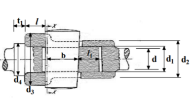
A cotter is a steel component with a flat wedge shape. This is used to firmly connect two rods so that motion can be transmitted in the axial direction without rotating. Along the axis of the rods, tensile or compressive forces can be applied to these joints. A link between a piston, a valve rod, and its stem are examples. The cotter is driven into a slot produced by the socket and the rod, and one of the rods has a socket end into which the second rod is inserted. The rod is driven into the socket when the cotter is hammered in because it tapers in width (usually 1:24) on one side only. To make it self-locking, the taper on both edges must be less than the total of the friction angles for both edges, i.e. 1 212 + +, where 1 and 2 are the angles of taper on the rod edge and socket edge of the cotter, respectively, and 1, 2 are the corresponding angles of friction. This also means that if taper is only applied to one side, the self-locking value is + 1 2. The driven cotter draws the two components of the joint closer until the socket end comes into contact with the cotter on the rod end, thanks to clearances between the cotter and slots in the rod end and socket.
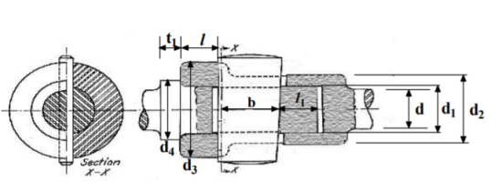
Empirical relations used for designing
|  |
Failures of a cotter joint used for checking the design developed from empirical relations
Sr. No | Failure modes | Relation |
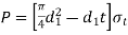
1 | Tension failure of rod at diameter d |  |
2 | Tension failure of rod across slot | 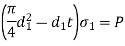 |
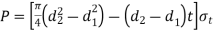
3 | Tensile failure of socket across slot | 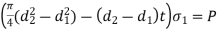 |
4 | Shear failure of cotter |  |
5 | Shear failure of rod end |  |
6 | Shear failure of socket end | 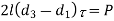 |
7 | Crushing failure of rod or cotter |  |
8 | Crushing failure of socket or rod | 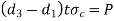 |
9 | Crushing failure of collar | 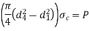 |
10 | Shear failure of collar |  |
Bending of cotter joint
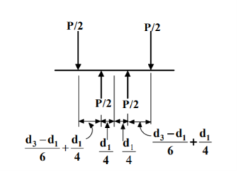
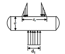
Maximum bending moment |  |
Bending stress | 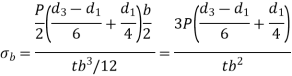 |
Design procedure for cotter joint
- Calculate diameter

- Calculate Thickness

- Calculate
 diameter of spigot on basis of tensile stress
4. Calculate Outside diameter  of socket
- Calculate
 socket collar diameter and
  spigot collar diameter

- a = c= 0.75d
- Calculate width b and select the max value
- By shear

- By bending
7. Check crushing and shear stress in spigot
- Crushing

- Shear

8. Check crushing and shear stress in socket
- Crushing
- Shear
9. Calculate thickness 
Key Takeaway:
A cotter is a steel component with a flat wedge shape. This is used to firmly connect two rods so that motion can be transmitted in the axial direction without rotating.
A knuckle joint is a tensile joint that connects two rods. This joint allows for angular misalignment of the rods and, properly directed, can withstand compressive loads. Different forms of connections, such as tie rods and tension links in bridge structures, are made with these joints. One of the rods has an eye at the end of the rod, while the other is forked with eyes on both legs. A collar and a split pin secure a pin (knuckle pin) put through the rod-end eye and fork-end eye.
Empirical relations used for designing
d = diameter of rod
| |
      
| 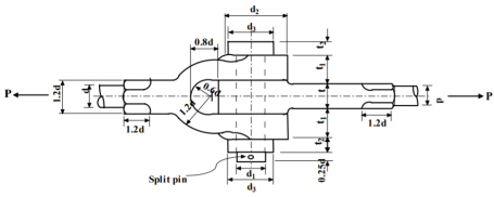 |
Failures of a knuckle joint used for checking the design developed from empirical relations
Failure | Relations |
|
Failure of rod in tension |  |
 |
Failure of knuckle pin in double shear |  | |
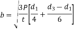
Failure of knuckle pin in bending |  | |
Failure of rod eye in shear |  | |
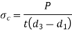
Failure of rod eye in crushing |  | |
Failure of rod eye in tension |  | |
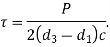
Failure of forked end in shear |  | |
Failure of forked end in tension | 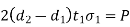 | |
Failure of forked end in crushing |  |
Design procedure for Knuckle joint
The empirical dimensions addressed above were developed after extensive experience with a specific service. The practical value of these aspects outweighs the theoretical analysis.
As a result, when building a knuckle joint, a designer should examine empirical relationships.
- Find the diameter of the rod
d = Diameter of the rod

2. Use empirical relations to find following
Diameter of knuckle pin

Outer diameter of eye

Diameter of knuckle pin head and collar

Thickness of single eye or rod end

Thickness of fork

Thickness of pin head

3. Calculate all stresses from failure table and see if they are less than permissible stress, if they are less the design is safe
4. Draw the scaled sketch with dimension
Key Takeaway:
A knuckle joint is a tensile joint that connects two rods. This joint allows for angular misalignment of the rods and, properly directed, can withstand compressive loads. Different forms of connections, such as tie rods and tension links in bridge structures, are made with these joints
Lever
A lever is a rigid rod or bar that pivots at a point and can rotate around the pivot point, also known as the fulcrum. Levers are used to lift a load with a minimal amount of effort. Mechanical advantages refer to the ratio of lifted load to effort. Leverage is defined as the ratio of the length of the effort arm to the length of the load arm. The levers are classified based on the application of load and effort.
- One arm lever: the hand lever, the foot lever and the cranking lever are examples. It just has one arm, which is an effort arm. This kind of lever is for the application of external torque
- Two Arm Lever: According to position of fulcrum they are classified as below
P= effort, W= load, F= fulcrum,
W/P (Mechanical advantage) = l1/l2 (leverage)
Class 1 | Class 2 | Class 3 |
Both the load and effort arms are the same length. The fulcrum pin pivots between the load and effort arms, | The effort arm is longer than the load arm | The effort arm is smaller than the load arm |
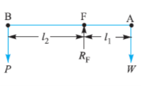 | 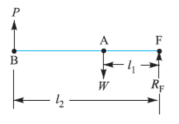 | 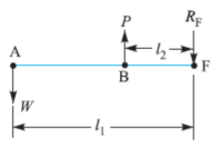 |
I.C. Engine, beam of a balance, handle of hand pump, bell crank | Safety valve | Stapler, pinning fork |
Mechanical advantage is depends upon position of F | Mechanical advantage is than one.
| Mechanical advantage is less one.
|
Key Takeaway:
A lever is a rigid rod or bar that pivots at a point and can rotate around the pivot point, also known as the fulcrum. Levers are used to lift a load with a minimal amount of effort. One arm lever: the hand lever, the foot lever and Two Arm Lever are different types of levers
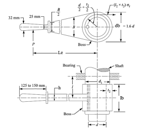
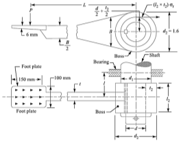
The maximum effort or force applied by a man may be assume as 300 N to 400 N for hand lever and 600 N to 800 N for foot lever
Let Le is effective length of arm , l be overhead length of shaft,  permissible tensile stress,
  permissible shear stress
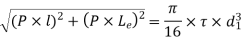
Twisting Moment is given 
Shaft under pure torsion =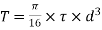
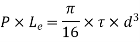
- The diameter of shaft (d) is obtained by combining above two equations
2. Diameter of shaft at the center of bearing (d1) is found out by combining bending moment and twisting moment
Bending Moment =
Twisting Moment 
Equivalent Moment 
Also, 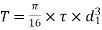
3. Diameter of the boss of the lever = db=1.6d,
4. of boss = lb= d or 1.5d
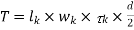
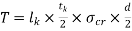
5. Design of key
- Key under shear failure
- Key under crushing failure
- Lever cross section
- Let b be width of lever, t be thickness of lever, the lever is subjected to bending moment
Key Takeaway:
Hand/Foot lever is similar to one arm lever. The maximum effort or force applied by a man may be assume as 300 N to 400 N for hand lever and 600 N to 800 N for foot lever is a
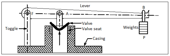
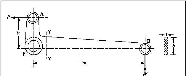
It's utilized to keep the pressure inside the boiler at a safe level. When the pressure inside the boiler reaches a safe level, the extra steam is automatically released through the valve. The valve is supported by a gunmetal seat that is attached to a casing on the boiler. A pin to the toggle pivots one end of the lever at the fulcrum F, while the other end carries the weights. The force P generated by the weights at B keeps the valve on its seat against the upward steam pressure. When the steam pressure pressing upward on the valve exceeds the normal limit, the weights and distance from the fulcrum are changed so that the valve and the lever with its weights are lifted. As a result, the extra steam escapes until the pressure reaches the appropriate level. The lever might be designed in the same way as the other levers. The maximum steam load (W) at which the valve will blow off is calculated as follows:
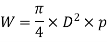
p is steam pressure, D is diameter of valve
Design Procedure
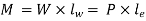
- Determination of effort/load
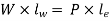
Let W represent the load and P represent the effort at the load and effort arms of length lw and le, respectively. By measuring the moment around the fulcrum, the final load/effort can be computed.
Get W, 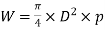
Get P, 
Get RF = W – P
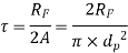
2. Design of fulcrum pin
The fulcrum pin holds the lever in place and allows it to oscillate. The fulcrum pin is subjected to bearing pressure and direct shear stress due to the relative motion of the lever on the pin
- Bending
This is used to calculate 

Here  are fulcrum pin length and diameter and
  is assumed typically.
b. Direct Shear
This is used to check safety of design using calculated  and permissible shear stress

3. Design of Boss of Lever Diameter
- When there is relative motion between the fulcrum pin and the boss of a lever, a brass bush with a thickness of 2 mm to 3 mm should be inserted as a bearing in the boss of the fulcrum lever so that replacement is simple when wear occurs. But it is not mandatory
- If bush is used
 (2 x bush size in mm)
Ii. If bush is not used

Iii. 
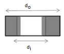
Here  = outer diameter
  = inner diameter
 = length of the boss of lever respectively
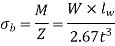
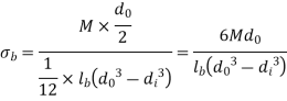
b. Maximum bending moment in Boss
 ,
, 
For Rectangular c/s
| b=width, t =thickness b= 2t to 4t Here assumed b=4t | 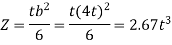 |
The two arms of a bell crank lever are at right angles to one another. Levers of this sort are used in railway signalling, Hartnell governors, and the drive for condensor air pumps, among other things. The bell crank lever's arms might have a rectangular, elliptical, or I-section shape.
Design procedure
- Determination of effort/load
Let W represent the load and P represent the effort at the load and effort arms of length lw and le, respectively. By measuring the moment around the fulcrum, the final load/effort can be computed.
Resultant fulcrum reaction (RF) =
2. Design of fulcrum pin
The fulcrum pin holds the lever in place and allows it to oscillate. The fulcrum pin is subjected to bearing pressure and direct shear stress due to the relative motion of the lever on the pin
- Bending
This is used to calculate 

Here  are fulcrum pin length and diameter and
  is assumed typically.
b. Direct Shear
This is used to check safety of design using calculated  and permissible shear stress
3. Design of Boss of Lever Diameter
- When there is relative motion between the fulcrum pin and the boss of a lever, a brass bush with a thickness of 2 mm to 3 mm should be inserted as a bearing in the boss of the fulcrum lever so that replacement is simple when wear occurs. But it is not mandatory
- If bush is used
 (2 x bush size in mm)
Ii. If bush is not used

Iii. 
Here  = outer diameter
  = inner diameter
 = length of the boss of lever respectively
b. Maximum bending moment in Boss
Here 
The outside diameter of the boss can be calculated using this equation, or the bending stress should be tested.
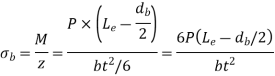
4. Lever Design in Bending
Bending Moment 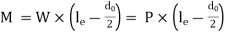
Cross section h is height, b is thickness of lever c/s | Assume | Z |
Rectangular lever 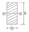
| h= 2b to 4b |  |
Elliptical Lever  | h= 2b to 2.5b
|  |

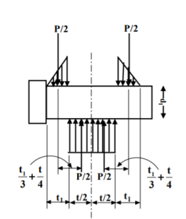
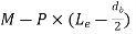
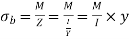
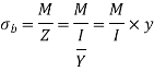
It was assumed that the force's line of action goes through the cross-centroid. Section's Certain mechanical components are subjected to an external tensile or compressive force that does not travel through the cross-centroid section. An example of such eccentric loading can be seen in the diagram below (a). As indicated in b) and (c), the eccentric force P can be replaced by a parallel force P travelling through the centroidal axis and a couple (P x e) according to the principle of statics. The force P generates a tensile stress of magnitude (P/A) to be uniformly distributed in (b). The couple in (c) creates bending stress of magnitude (Pey/I). The principle of superimposition of stresses is used to derive the resulting stresses at the cross-section. They're provided by,


Design Procedure
Calculate Permissible shear Stress using FOS 
Calculate diameter 
Calculate Permissible tensile Stress using FOS
Calculate Thickness of Plates 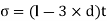
Key Takeaway
Certain mechanical components are subjected to an external tensile or compressive force that does not travel through the cross-centroid section
The principle of superimposition of stresses is used to derive the resulting stresses at the cross-section

References:
- Design of Machine Element VB Bhandari
- Machine Design RS Khurmi, JK Gupta


