Unit - 2
Design of Shafts, Keys and Couplings
- When shaft is subjected to axial load

- When shat is subjected to bending moment

- When shaft is subjected to torsional shear stress

- When shaft is combined load using Mohr Circle


- Using maximum Principle stress theory and equation 4,2,3


As shaft is uses the ductile material this theory is not used
- Using Maximum Shear stress theory and equation 5,2,3


Also, according to theory, Ssy =0.5Syt

Equation 8 and 9 is used to Design Shaft
Hollow Shaft
For hollow shaft, let ratio of diameter be

Then from formulas are updated as follow


Key Takeaway
For designing Shaft Maximum Shear Stress Theory is used and following are equation


For hollow shaft

Shaft has torsional rigidity if it doesn’t twist under action of external torque. It is important to design the Shaft on Torsional Rigidity Basis for some application like machine tool spindle where angle  of twist per meter length.
  is given by

In degrees,

For circular shaft

From 2 and 3

Equation 4 is used to design shaft on Torsional Rigidity Basis, Max permissible for machine tool application is  , Max permissible for line shaft application is
Hollow Shaft
For hollow shaft, let ratio of diameter be

Then from formulas are updated as follow

Key Takeaway
Equation given below is used to design shaft on Torsional Rigidity Basis,

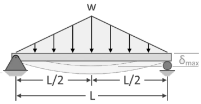
Particular components are intended for lateral stiffness rather than strength in certain applications. When a component does not deflect or bend excessively as a result of external forces or moments, it is said to be rigid. In these circumstances, the design criterion is permissible deflection. The meshing of the gear teeth is not suitable when a transmission shaft holding a gear is deflected. This causes an unequal weight distribution throughout the gear's face width, resulting in early failure. The shaft displacement also causes a mismatch between the shaft and bearing axis, resulting in uneven bearing surface wear.
The shaft deflection affects the radial clearance in a hydrodynamic bearing. Rigidity governs the accuracy of the machining procedure in the design of machine tool components. The transmission shaft's maximum permitted deflection is usually calculated as
 = (0.001) L to (0.003) L,
Where L is the span length between the two bearings.
The maximum allowable deflection at the gear is calculated as  = (0.01)m, where m is the gear teeth module. In practice, the lateral stiffness of a structure can be improved by reducing the span length, increasing the number of supports, reducing the number of joints, and pre-loading the components. Lubricate the contact surfaces with a high-quality lubricant; Choose a cross-section like an I or a tubular section that has the cross-sectional area away from the neutral axis.
Design Procedure
- Permissible

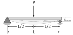
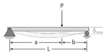
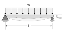
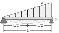
- Find Deflections at each gear
 using table given below
 - Compare the Deflections at all gears and select maximum

- Compare it with permissible stress
 to get I
 - From I, shat diameter can be calculated as

 |  |
 |  |
 |  |
 |  |
 |  |
 |  |
 |  |
Key Takeaway
- If a component does not deflect or bend excessively as a result of external forces or moments, it is said to be rigid. In these circumstances, the design criterion is permissible deflection

- Find
 using above table and compare it with permissible stress equation to get Shat diameter
According ASME code the permissible  is taken as 30 % of yield stress in tension and 18% of ultimate tensile strength, whichever minimum if keyways is not present
 Whichever minimum
If keyways are present these values are further reduced by 25%. According to ASME code kb and kt factors are multiplied for shock and fatigue ASME is based on maximum shear stress theory

 is combined fatigue and shock factor for bending moment
 is combined fatigue and shock factor for torsional moment
Some typical values are,
Application |  |  |
Load gradually applied | 1.5 | 1.0 |
Load suddenly applied (Minor shock) | 1.5 to 2.0 | 1 to 1.5 |
Load suddenly applied (Heavy shock) | 2 to 3 | 1.5 to 3 |
Key Takeaway
This equation is used to design shaft using ASME CODE

Keys
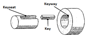
A key is a machine component that connects the transmission shaft to spinning machine components such as pulleys, gears, sprockets, and flywheels. The key's principal role is to transmit torque from the shaft to the mating element's hub and vice versa. The key's second purpose is to prohibit relative rotational motion between the shaft and the attached machine unit, such as a gear or pulley. Except in the case of a feather key or a splined connection, the key also prohibits axial motion between two pieces in most circumstances. The keyway is a recess or groove carved on the shaft or in the hub to receive the key. A vertical horizontal milling cutter is commonly used to cut the keyway. The keyway causes tension to build up in the shaft, making the portion fragile. The biggest disadvantage of a keyed joint is this.
Material
To withstand shear and compressive pressures caused by torque transfer, keys are manufactured of simple carbon steels such as 45C8 or 50C8. Steel with a tensile strength of not less than 600 N/mm2 shall be used for the key according to Indian requirements.
Types of Keys
- Saddle key
A saddle key is a key that only fits in the hub's keyway. The shaft in this example does not have a keyway. Hollow and flat saddle keys are the two varieties of saddle keys.
- Sunk key
A sunk key is one that fits half of its thickness into the keyway on the shaft and the other half into the keyway on the hub. As a result, keyways are needed on both the shaft and the hub of the mating member. This is the most common type of key, and it can have a rectangular or square cross-section.
- Feather key
A feather key is a parallel key that is attached to either the shaft or the hub and allows relative axial movement between the two. The feather key is a sort of buried key with a uniform height and width.
- Woodruff key
A sunk key in the shape of an almost semicircular disc of uniform thickness is known as a Woodruff key. The shaft's keyway is shaped like a semicircular recess with the same curve as the key. The lower half of the Woodruff key fits into the shaft's circular keyway. The hub's keyway is created in the traditional way. The projecting section of the Woodruff key fits into the hub's keyway. The Woodruff key tilts and aligns itself on the shaft once it is in place.
Design of Rectangular Key
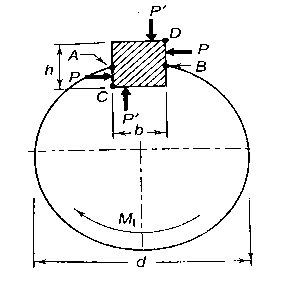
Let b be width and h be height. Equal and opposite forces denoted by P acts on Key and prevent it from rolling. The torque  is transmitted by means of P. P is assumed to be acting tangentially and d is shaft diameter

The key is designed using two failures shear and compressive
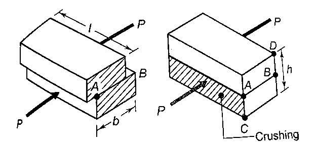
- Shear Failure
Shear failure occurs at AB plane

From equation 1

- Crushing Failure
Compressive failure occurs on surfaces AC to DB h
From figure 

From equation 1

Key Takeaway
This equation is used for designing rectangular key

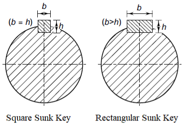
The key is designed similar to rectangular only h =b
- Shear Failure

Crushing Failure

Key Takeaway
This equation is used for designing rectangular key

Kennedy key consist of two square keys as shown in figure As seen in Fig. The Kennedy key is made up of two square keys. The hub is bored off-center in this case, and the two keys force the hub and shaft into a concentric position. For heavy-duty applications, the Kennedy key is employed. The Kennedy key's analysis is similar to that of the flat key.
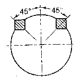
Failure due to shear stress and failure owing to compressive stress are the two criterion used. Figure depicts the forces acting on one of the two Kennedy keys. The torque transmitted by each key is one half of the total torque because there are two keys. The transmitted torque is responsible for the two equal and opposite forces P. The force P's exact position is unclear. So, it is assumed to be acting tangentially

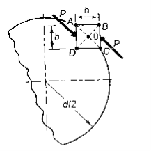
- Shear Failure
Shear failure occurs at AC plane

From equation 1

- Crushing Failure
Compressive failure occurs on surfaces AC to DB h
From figure 

From equation 1

Key Takeaway
This equation is used for designing rectangular key


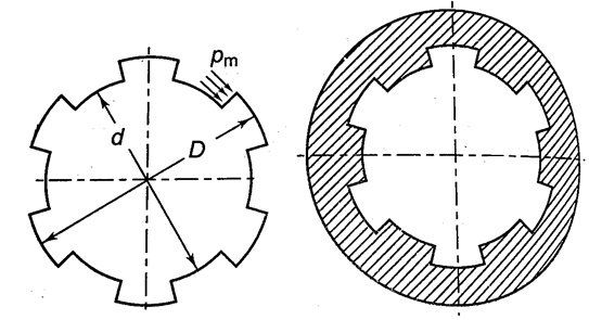
Splines are keys that are molded into the shaft. When there is axial motion between the shaft and the hub, they are employed. This type of architecture is required by the gear shifting mechanism in automotive gearboxes. Milling is used to cut splines on the shaft, and broaching is used to cut splines on the hub. Figure below shows a splined connection using straight splines.
Involute splines: Splines that bend inward Concentric external and internal gear teeth are used to make involute splines. They have a 30° pressure angle and are stub teeth. Modules define these splines. Because of their higher strength-to-size ratio, involute splines are more popular than straight splines. Self-centering, involute splines adjust to an even load distribution. Involute splines, on the other hand, are more expensive than straight splines.
Serrations: Serrations with straight sides are employed in applications where the overall size of the assembly must be kept as compact as feasible. As interference joints, they are employed. Serration joints can also be utilized to achieve modest angular relative adjustments between linked parts.
In figure above
D= major diameter
d= minor diameter
l= length of hub
n = number of splines
The torque carrying capacity of spline is given by

Here
 is transmitted torque
 is pressure on spline
A is area of spline, 
 is mean radius
Substituting values in 1

The permissible pressure on spline is 6.5 N/mm2
Key Takeaway
This equation is used for designing rectangular key

Coupling
A coupling is a mechanical mechanism that connects two rotating shafts to one other permanently. The most typical use of a coupling is to unite the shafts of two distinct machines that were manufactured or purchased separately in order to create a new machine. To lift water from a well, a coupling is used to connect the output shaft of an engine to the input shaft of a hydraulic pump. In machine tools, a coupling connects the output shaft of an electric motor to the input shaft of a gearbox. A coupling is also used to connect an electric motor's output shaft to a compressor's input shaft.
Alignment
The shafts that the coupling will join may have collinear axes, intersecting axes, or parallel axes with a short gap between them. When two parallel shafts are close together, an Oldham coupling is utilized to link them. To link two shafts with intersecting axes, Hooke's coupling is employed. Rigid or flexible couplings are utilized when the axes are collinear or in the same line.
Difference between rigid and flexible coupling
Misalignment of the shaft axis is not tolerated by a rigid coupling. It can only be utilized when the two shafts are perfectly aligned. The flexible coupling, on the other hand, can tolerate 0.5° of angular misalignment and 5 mm of axial displacement between the shafts due to the provision of flexible parts such as bush or disc. Shocks and vibrations are absorbed by the flexible parts in the flexible coupling. In rigid coupling, there is no such provision. It can only be utilized in motions that are devoid of shocks and vibrations. Rigid coupling is a basic and low-cost option. Due to the additional pieces, flexible coupling is more expensive.
Characteristics of Good Coupling
- The coupling needs to be able to transfer torque from the driving shaft to the driven shaft.
- The connection should maintain good alignment between the two shafts.
- For repairs and adjustments, the coupling should be simple to assemble and detach. Accidents can occur when revolving bolt heads, nuts, key heads, and other projecting pieces break. They should be protected by giving the flanges a proper form or by using guards.
Rigid Flange Coupling
Two flanges, one keyed to the driving shaft and the other to the driven shaft, make up a flange coupling. The two flanges are joined by four or six bolts that are positioned in a circle concentric with the shaft axes. Through the key, power is transferred from the drive shaft to the left side flange. It is then passed through the bolts from the left side flange to the right side flange. Finally, the key transmits power from the right side flange to the driven shaft. Because a flange coupling is a rigid type of coupling, accurate positioning of the axes of two shafts is required.
The advantages of rigid flange couplings are as follows:
- Rigid couplings can transmit a lot of torque.
- Rigid coupling is simple to put together and take apart.
- Rigid couplings are easy to construct. It is simple to develop and produce.
The following are the drawbacks of rigid flange couplings:
- I It is a sort of connection that is stiff. It can't stand when the axes of two shafts aren't aligned.
- It can only be utilized in motions that are devoid of shocks and vibrations.
- It necessitates a larger radial space.
Design Procedure of Rigid Flange Coupling
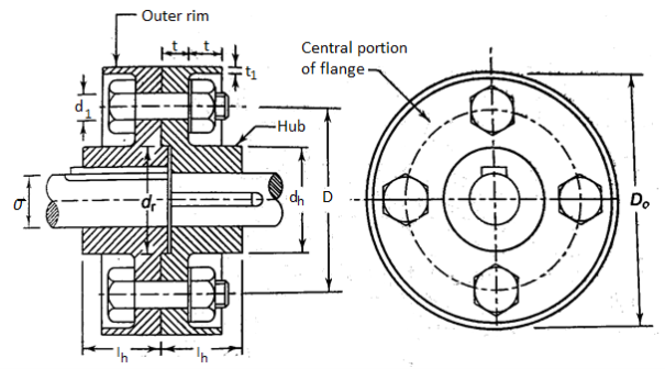
- Diameter of Shaft

Also,

2. Flange Dimension
- Outside diameter of hub

- Length of hub = effective length of key

- Pitch circle Diameter of bolts

- Thickness of flanges

- Thickness of protecting rim

- Diameter of spigot and recess

- Outside diameter of flange

- Calculate Torsional shear stress in the hub and compare it with permissible shear stress
 and
and 
- Calculate shear stress at Junction of hub and compare it with permissible shear stress

3. Bolts and Diameter
Number of bolt is determined by shaft diameter d
N=3 for 40 mm and below diameter.
N=4 for 40 mm to 100mm and below diameter
N=6 for 100 mm to 180 mm and below diameter
- For Reamed and Grounded fitting of bolts Power is transmitted by shear resistance
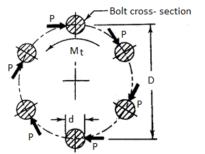
- Force acting P and Torque
 transmitted by coupling,

- The bolt is subjected to direct shear given by,

- From 1 and 2

- For Large Clearance fitting of bolts Power is transmitted by Friction
- Torque
 transmitted by coupling with initial pretension
  is
is
- Torque

- Friction Radius is given as

- Here
 Outside radius of flange
Radius recess 
 is Coefficient of Friction
- For Checking the crushing Failure
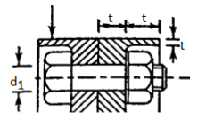
Crushing area of bolt =
Crushing area of n bolt =
Compressive Force =
Torque 
That is

This equation is used to check failure
4. Key Design
Design the key as mention in Key design section (1.5) assuming 
Flexible Coupling
Rigid coupling can only be employed when the axes of two shafts are perfectly aligned and the motion is free of vibrations and shocks. Perfect shaft alignment is impossible to achieve in practice. Deflection of shafts due to lateral forces; inaccuracy in shaft mounting due to manufacturing tolerances; employment of two separately made items such as an electric motor and a worm gear box; and thermal expansion of the parts are all causes of misalignment. When a rigid coupling is employed in certain situations, the misalignment creates excessive bearing reactions, which causes vibrations and wear. Flexible couplings are utilized to solve this problem. Between the driving and driven flanges, a flexible element such as a rubber bush is used in a flexible coupling. This flexible rubber bush not only compensates for the misalignment, but it also absorbs shocks and vibrations.
Construction of Bushed-Pin Flexible Coupling
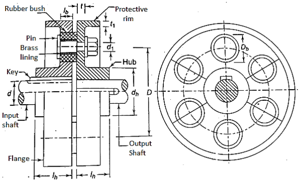
Figure depicts the flexible coupling's construction. Except for the use of a rubber bush and pins in place of bolts, it is similar to the rigid type of flange coupling. The coupling is made up of two flanges, one for the input shaft and one for the output shaft. The two flanges are joined together by four or six pins. The pin is secured to the output flange at one end by a nut. In the input flange, where a rubber bush is mounted over the pin, the diameter of the pin is increased. The inner surface of the rubber bush is lined with brass. The lining protects the inner surface of the rubber bush from wear. The key transmits power from the input shaft to the input flange. It is then transmitted through the rubber bush from the input flange to the pin. The power is then transmitted to the output flange via shear resistance by the pin. Finally, the key transmits power from the output flange to the output shaft.
The advantages of Flexible couplings are as follows:
- It can withstand a lateral or axial misalignment of 0.5 mm and an angular misalignment of 1.5°.
- It absorbs vibrations and prevents shock transmission from one shaft to the other.
- It is capable of transmitting high torques.
The following are the drawbacks of Flexible couplings:
- Because of the additional parts, the cost of flexible coupling is higher than that of rigid coupling.
- It necessitates more radial space than other types of coupling.
Design Procedure of Flexible Coupling
- Diameter of Shaft

Also,

2. Flange Dimension
- D is shaft diameter, N is no of pins
- Outside diameter of hub

- Length of hub = effective length of key

- Pitch circle Diameter of bolts

- Thickness of flanges

- Thickness of protecting rim
 Calculate Torsional shear stress in the hub and compare it with permissible shear stress
 and
and 

3. Diameter of pin 
- Calculate shear stress by pin


4. Dimension of Bush
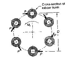
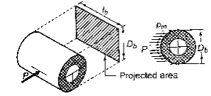
- Calculate outer diameter of bush


- Calculate effective length as

5. Key Design
Design the key as mention in Key design section (1.5) assuming 
References:
- Design of Machine Element VB Bhandari
- Machine Design RS Khurmi, JK Gupta