Unit - 3
Design of Power Screws
Power Screw
A power screw is a mechanical device for conveying power and turning rotary motion into linear motion. A translation screw is another name for a power screw. Rather than clamping the machine components, it uses helical translatory motion of the screw thread to convey power. The following are the major applications of power screws:
- Raising the load, e.g., screw-jack;
- Obtaining correct motion in machining operations, e.g., lathe lead-screw; (
- Clamping a work piece, e.g., vice; and
- Loading a specimen, e.g., universal testing machine.
Parts and Functions
The power screw consists of three parts: a screw, a nut, and a component that holds either the screw or the nut in place. Power screws can operate in two ways, depending on the holding arrangement. The screw may rotate in its bearing while the nut moves axially in some instances. This category includes items like the lathe's lead screw. The nut is held stationary in other applications, while the screw moves in an axial direction. This category includes items such as a screw jack and a machine vice.
Advantages:
- The design of a power screw is straightforward.
- The production of a power screw is simple and does not necessitate specialized machinery. A power screw has a significant mechanical advantage. A weight of 15 kN can be increased with as little as 400 N of effort.
- In machine tool applications, a power screw delivers precisely controlled and very accurate linear motion.
- A power screw is made up of only a few components. This lowers the cost and improves the reliability of the system.
- A self-locking power screw is possible to design.
Disadvantages:
- The efficiency of a power screw might be as low as 40%. With the exception of the lead screw, it is not employed in continuous power transmission in machine tools. Power screws are mostly employed for intermittent motion, such as raising a load or triggering a system.
- High thread friction causes the screw or nut to wear out quickly. The nut on square threads is usually made of soft material and is replaced when it wears out. To compensate for wear on trapezoidal threads, a split-type nut is employed. As a result, wear is a significant issue in power screws.

Terminology of power Screw
- Pitch
Pitch is defined as the distance between a point on one thread and the matching point on the neighbouring thread measured parallel to the screw's axis. The letter p stands for it.
- Lead
The lead is defined as the distance measured parallel to the screw's axis that the nut will advance in one screw revolution. The letter l stands for it. The lead of a single-threaded screw is the same as the pitch. The lead on a double-threaded screw is twice the pitch, and so on.
- Nominal diameter
The nominal diameter is the screw's largest diameter. It's also known as the major diameter. The letter d stands for it.
- Core Diameter
The screw thread's core diameter is the smallest diameter. It's also known as a minor diameter. The letters de designate it.
- Angle of the Helix
The helix angle is defined as the angle formed by the thread's helix and a plane perpendicular to the screw's axis. The lead and the screw's mean diameter are connected to the helix angle. It's also known as the lead angle. The helix angle is represented by the letter α.
Square Threads Lifting Torque
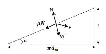
The screw is thought of as a slanted plane with an inclination. The following forces act at a place on this inclined plane when the weight is raised:
- Load W: It acts in a vertically downward manner at all times.
- Normal Reaction N: It works perpendicular to the inclined plane (normally).
- Frictional Force
 N: Frictional force is the force that acts in the opposite direction of motion. Because the load is travelling up the inclined plane, frictional force operates in a downward direction along the inclined plane.
 - Effort P: Effort P works in the opposite direction of the load W. It has the ability to act either to the right or to the left. To overcome friction and raise the load, it should act to the right.
Horizontal forces 
Vertical forces 
Dividing both


But 


The torque required to raise the load is


Square Threads Lowering Torque

The forces acting at a point on the inclined plane when the load is being lowered are
- Load W is vertically down
- Normal Reaction N: It is perpendicular (normal) to the inclined plane and operates vertically downward.
- Frictional Force
 N: Frictional force acts in the opposite direction of motion. Because the load is travelling down the inclined plane, frictional force operates in an upward direction along the inclined plane.
 - Effort P: The effort P is parallel to the load W. To overcome the friction and lessen the load, it should move to the left.
Horizontal forces 
Vertical forces 
Dividing both


But 


The torque required to raise the load is


Trapezoidal Threads
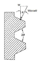
The force acting on the threads of square and trapezoidal threads is fundamentally different. W is the axial load raised by the screw in the case of square threads. It's also the normal force operating on the surface of the thread. These two forces are different in trapezoidal and acme threads. W is the axial force on the screw, while (W/cosϴ) represents the normal force on the thread surface (W sec ϴ). The normal force determines the frictional force. As a result, the thread angle has the effect of increasing the frictional force by a factor of term (sec ϴ). In the case of trapezoidal threads, the coefficient of friction is taken as ( sec ϴ) instead of (
 ) to account for this impact.
Lifting Torque


Lowering Torque


Key Takeaway
Thread | Lifting torque | Lower torque |
Square | 
| 
|
Trapezoidal | 
| 
|

In many uses of the power screw, collar friction exists in addition to thread surface friction. With the help of Fig. 1, the principle of collar friction may be described. Under the action of the load W, the cup remains fixed, whereas the collar, which is integrated with the screw, spins as the load is raised or dropped. As a result, from diameter Di to Do, there is relative motion between the cup and the collar at the annular interface. Collar friction occurs as a result of this relative motion. Using uniform pressure theory or uniform wear theory, the torque required to overcome this friction, or collar friction torque (M), can be calculated.
Uniform Pressure Theory (New Collar)

Uniform wear Theory

Key Takeaway
In most cases Collar friction is given by Uniform wear Theory

"If the coefficient of friction is equal to or greater than the tangent of the helix angle, a screw is self-locking."
Explanation
Case 1
As can be observed, the torque required to lower the load is negative when  . It denotes a situation in which no force is needed to lessen the load. Unless a restraining torque is given, the load will begin to turn the screw and descend. Overhauling of the screw is the term for this ailment. This issue is also known as screw back driving. In screw-jack applications, this characteristic is useless. It is, however, useful in other applications, such as a Yankee screwdriver. The barrel of this sort of screwdriver has a high-lead thread, while the handle is a nut. The barrel spins and presses the wood screw into position while the worker pushes the handle axially down.
Case 2
Positive torque is necessary to lessen the load when ( ). Unless some effort P is provided, the load will not turn the screw or drop on its own in this position. The screw in this example is believed to be self-locking. Without the use of a brake, a self-locking screw will keep the load in place. In screw-jack applications, this is a particularly beneficial attribute. The driver, for example, can jack up the automobile and leave the jack handle in place while performing the work. The automobile will not descend on its own throughout the work, allowing the driver to focus on the task at hand.
From above Explanation For self-locking screw


When the coefficient of friction (u) is low, self-locking of the screw is impossible. Lubrication reduces the coefficient of friction between the screw and the nut surfaces. The load descends on its own due to excessive lubrication. When the lead is large, the screw's self-locking feature is lost. With a number of starts, the lead grows. The lead is twice the pitch for a double-start thread and three times the pitch for a triple-threaded screw. From a self-locking standpoint, a single-threaded screw is preferable to a multiple-threaded screw.
Key Takeaway
- If the coefficient of friction is equal to or greater than the tangent of the helix angle, a screw is self-locking."

- This property is useful for screw jack
Square Threaded screw
Output: force times distances travelled= 
Input: Effort times distances travelled = 


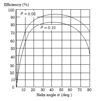
Maximum efficiency occurs at 45 , is given by

Trapezoidal Threaded screw
Similarly

Substituting,  from torque analysis

Replace  for accounting effects of angle

Self-Locking screw
Similarly, from above


In self-Locking Screw  lets
lets 


Therefore, Efficiency of Self Locking screw is less than 50%
Overall Efficiency
The Overall Torque or External Torque required to raise the handle  comprises of torque required to overcome friction
  and collar friction torque

Output: force times distances travelled= 
Input: Effort times distances travelled = 
Efficiency

Key Takeaway
Types | Efficiencies |
Square |  
|
Trapezoid | 
|
Self-Locking |  |
Overall |  |
Screw

1. Material 40C8, 45C8, 30C8, 40Crl
2. Design dc considering pure compression
σ=W/(π/4) x dc2
3. Select Standard Threads from Data Book according to dc
Select Nominal Diameter dp
dm (mean diameter) =d-p/2
dc =d-p
4. Find torque required to overcome friction 

l= p for single start screw


5. Collar friction torque 
Uniform Pressure Theory (New Collar)

6. Overall Torque

7. Stresses
- Stresses at section XX
- Torsional shear stress due to torque
 ,
, - Bending force due to force on handle
- Max shear stress at XX
- (Sys=0.5Syt)

- Torsional shear stress due to torque
- Stresses at section YY
- Direct compressive stress
- Torsional shear stress due to collar friction
- Max shear stress at YY
- Direct compressive stress
If in both sections  is less than permissible stresses, screws are safe
Nut Design
- Calculate Height of nut considering bearing pressure
- Here Z is no of Threads,
- Height,

- Thickness, t=

- Check the stresses on threads of screw and nut
- Shear Stress on Screw Threads
- Shear Stress on Nuts Threads
- Shear Stress on Screw Threads
Clamp Design
- Determination of length of handle
- Let lh be length of handle

- Add grip to handle of 40 to 50 mm
- Let lh be length of handle
- Frame design
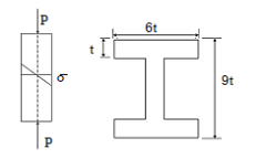
Frame is subjected to combined direct andbending stresse

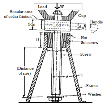
- Material Selection
Name of Component | Material | Subjected to | FOS | Values Hand operated P  
|
Frame | FG200 Cast Iron- Easy to manufacture complex parts | Compressive Stresses | 5 |  |
Screw | 30C8 | Compressive and Bending | 5 |  |
Nut | Phosphor bronze Grade 1- Material must be soft than screw to reduce wear on screw | Wear Failure | 5 |  
 |
Handle | 30C8 | Bending Moment | 5 |  |
Cup | FG200 Cast Iron- FG200 Cast Iron- Easy to manufacture complex parts |
| 5 |  |
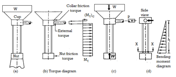
2. Design dc considering pure compression


3. Select Standard Threads from Data Book according to dc
Select Nominal Diameter dp
dm (mean diameter) =d-p/2
dc =d-p
4. Find torque required to overcome friction 

l= p for single start screw

Coefficient of friction is taken between 0.1 to 0.18


5. Collar friction torque 
Uniform Pressure Theory (New Collar)

6. Overall Torque

7. Stresses
- Stresses at section XX
- Torsional shear stress due to torque
 ,
, - Bending force due to force on handle
- Max shear stress at XX
- (Sys=0.5Syt)

- Torsional shear stress due to torque
- Stresses at section YY
- Direct compressive stress
- Torsional shear stress due to collar friction
- Max shear stress at YY
- Direct compressive stress
If in both sections  is less than permissible stresses, screws are safe
8. Buckling Consideration
- Once the load is raised to 500mm screw act as column and buckling failure must be checked
- Length of column for buckling is taken as 500+50 =550mm
- For circular c/s the slenderness ratio is given by,
k=
Slenderness ratio (l/k) =(500/k)
d. Check if screw is to be considered ad short column or long by comparing to critical ratio, The Screws one end is fixed, So the coefficient is taken as  0.25
0.25

If 


Nut Design
- Calculate Height of nut considering bearing pressure
- Here Z is no of Threads,
- Height,

- Thickness, t=

- Check the stresses on threads of screw and nut
- Shear Stress on Screw Threads
- Shear Stress on Nuts Threads
- Shear Stress on Screw Threads
Cup Design
- Do=1.6d
- Di=0.8d


Handle Design
- Determination of length of handle
- Let lh be length of handle

- Add grip to handle of 40 to 50 mm
- Let lh be length of handle
In some applications, very slow screw advancement is required for fine adjustment, whereas in other applications, very fast screw advancement is preferable. Reducing the pitch is one way to produce a little advance of the screw. Threads with a narrow pitch are weak. Multi-start threads are commonly used to achieve quick screw movement. The self-locking feature is influenced by the number of starts. Differential and compound screws are employed to address these challenges
Differential Screws

A differential screw is a mechanical device that consists of two screws in series that are positioned so that the resultant motion is the difference of the two screws' separate motions. With the help of Fig, the differential screw principle is explained. The composite screw is made up of two parts: the larger S, which has a pitch of 4 mm, and the smaller S2, which has a pitch of 3 mm. Both threads have the same helix hand, as they are both right-handed. S passes through the frame F in its larger form. On the smaller section S2, there is a square nut N. As seen in Fig., the nut cannot rotate and can only glide in an axial direction with regard to the frame. When viewed from the right side, the handle rotates one revolution in the clockwise direction. When the fingers are retained in the direction of rotation, the thumb indicates the direction of movement of the screw, according to the right-hand thumb rule. The nut's movement is in the opposite direction as the screws. With relation to the frame, the screw S will move 4 mm to the left. In relation to the frame, the nut N will move 3 mm to the right. The nut will move (4-3) mm to the left in relation to the frame as a result of this action. If the pitches of two screws are p1 and p2, the resultant motion is equal to (P1-P2) or the difference of the motions.
Compound Screws
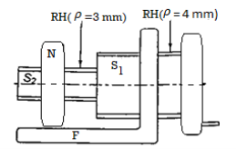
A compound screw is a mechanical device that consists of two screws connected in series, with the resultant motion equal to the sum of the two screws' individual motions. Figure 1 depicts a compound screw. Except for the hand of helix for the two screws, the configuration is similar to that of a differential screw. The bigger section S has right-handed threads, whereas the smaller half S has left-handed threads. The consequent movement of the nut with respect to the frame may be proven to be (4 +3) mm to the left. If the pitches of two screws are p and p2, the resultant motion is equal to (p1 + p2), or the sum of the individual motions.
Key Takeaway
- In some applications, very slow screw advancement is required for fine adjustment, whereas in other applications, very fast screw advancement is preferable
- Slow screw advancement: A differential screw is a mechanical device that consists of two screws in series that are positioned so that the resultant motion is the difference of the two screws' separate motions
- Very fast screw advancement: A compound screw is a mechanical device that consists of two screws connected in series, with the resultant motion equal to the sum of the two screws' individual motions
A recirculating ball screw, as depicted in Fig, is made up of a screw and a nut with a sequence of balls between their surfaces. Instead of having square or trapezoidal thread profiles, the screw and nut feature approximately semi-circular thread profiles. The balls progress in the grooves of the nut and screw when the screw is spun. They are gathered and returned at the conclusion of the nut. Ball bearing screw or simply ball screw are other names for the recirculating ball screw. Because backlash is eliminated, such screws are preloaded and provide precise motion. Because of the little friction, no heat is generated. High speeds of up to 10 m/min can be achieved using recirculating ball screws. Contact stresses are applied to the balls, screw, and nut. They're normally constructed of nickel chromium steel that's been heat treated to a hardness of 58 to 65 HRC on the surface.

Advantages
- There is sliding friction between the screw and nut threads in a traditional power screw. There is rolling friction between the balls and the grooves in the screw and nut in a recirculating ball screw. This significantly minimizes friction. A traditional power screw's efficiency can be as low as 40%. Because sliding friction is replaced by rolling friction, ball screws have a high efficiency of up to 90%.
- The disparity between the values of coefficient of static friction and coefficient of sliding friction causes the 'stick-slip' problem in conventional power screws. It's a significant flaw. It is practically removed in a recirculating ball screw, and the operation is smooth.
- A traditional power screw must be adjusted on a regular basis to accommodate for wear on the screw and nut surfaces. Due to the presence of a lubrication film between the contacting surfaces and protection from dirt particles, a recirculating ball screw is nearly wear-free.
- Recirculating ball screws have a higher load carrying capacity than ordinary power screws. Recirculating ball screw jacks are more compact and lightweight than traditional screw jacks with the same load carrying capacity.
Disadvantages
- A recirculating ball screw is significantly more expensive than a standard power screw.
- Because of their minimal friction, recirculating ball screws are frequently overhauled. As a result, a secondary brake is needed to keep the weight in place.
- Recirculating ball screws have major concerns with screw buckling and critical speed.
- In comparison to typical power screws, recirculating ball screws necessitate a high level of cleanliness. They are entirely enclosed to prevent extraneous particles from entering.
- For proper operation, recirculating ball screws require a thin film of lubrication between the balls and grooves in the nut and the screw. The lubrication of conventional power screws is simple.
Application
- Automobile steering gears
- Power actuators
- X-Y recorders of CNC machines
- Aircraft landing gear retractors
- Hospital bed adjustors
- Machine tool controls
Key Takeaway
- A traditional power screw's efficiency can be as low as 40%. Because sliding friction is replaced by rolling friction, ball screws have a high efficiency of up to 90%.
- Recirculating ball screws have a higher load carrying capacity than ordinary power screws.
References:
- Design of Machine Element VB Bhandari
- Machine Design RS Khurmi, JK Gupta


