Unit - 5
Threaded and Welded joints
A threaded joint is a separable joint of two or more machine parts held together by a threaded fastener such as a bolt and nut. The following are the key features of this definition:
Threaded joints are used to connect two or more machine parts. If necessary, these parts can be disassembled without causing any damage to machine parts or fasteners. As a result, threaded joints, unlike welded joints, are detachable. Thread is the fundamental component of these joints. A helical groove is cut on the surface of a cylindrical rod or cylindrical hole to form the thread. The threaded element can be in the form of a bolt and nut, a screw, or a stud. Threaded joints are commonly found in mechanical assemblies. Threads have been discovered on more than 60% of the parts. Threaded joints are popular because of the benefits they provide.
The following are the benefits of threaded joints:
(1) The components are held together by a strong clamping force. The clamping force is increased due to wedge action at the threads. There has been no loosening of the As a result, threaded joints are dependable joints.
(ii) The parts are assembled with a spanner. The spanner's length is long in comparison to the thread's radius. As a result, the mechanical advantage is greater, and the force required to tighten the joint is minimal.
(iii) Threaded joints have small overall dimensions as a result of their design compacted
(iv) The threads themselves are self-locking. As a result, threaded joints can be installed in any orientation-vertical, horizontal, or inclined.
(v) Threaded fasteners are inexpensive to produce. Their production is straightforward. Threaded components can be manufactured with high precision.
(vi) The threaded joints that connect the parts allow them to be detached as needed. This requirement is required in certain applications for inspection, repair, or replacement.
(vii) Threaded fasteners are standardized, and a wide range is available to suit a variety of operating conditions and applications.
Threaded joints have a number of drawbacks. These are their names: I Threaded joints necessitate the drilling of holes in the machine parts to be clamped. As a result, there is a concentration of stress near the threaded portion of the parts. These areas are prone to fatigue failure.
(ii) When subjected to vibrations, threaded joints loosen.
(iii) Threaded fasteners are regarded as a major impediment to efficient assembly. Tightening a screw in manual assembly can cost six to ten times the cost of the screw itself. As a result, the Design for Manufacture and Assembly (DFMA) standard recommends a minimum number of threaded fasteners.
Type of screw fastening
A threaded fastening is made up of three parts: a bolt or screw, a nut, and a washer.
- Bolt and Screw: There is a fundamental distinction between a bolt and a screw. A bolt is a fastener with a head and a straight threaded shank that is intended to be used in conjunction with a nut to clamp two or more parts together. When a bolt is threaded into a tapped hole in one of the parts rather than the nut, it is referred to as a screw. Although a bolt and a screw are similar, there is a significant difference in how they are assembled. A bolt is held stationary while torque is applied to the nut to form a threaded joint, and torque is applied to the screw to form matching threads in one of the parts.
- Nut: A nut is a small symmetrical part with matching internal threads that is usually hexagonal or square in shape.
- Washers: Simple washers are thin metallic discs with an annular shape. A washer's functions are to distribute the load over a large area on the surface of the clamped part and to provide a bearing surface over large clearance holes.
Threaded fasteners are classified based on their shape and application. The following are examples of common threaded fasteners:
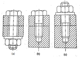
a) Through Bolts A through bolt is simply referred to as a 'bolt' or a 'bolt and nut.' The bolt is made up of a cylindrical rod with a head on one end and threads on the other.
b) The tap bolt is inserted into a threaded (tapped) hole in one of the connecting parts rather than a nut. The through bolt, on the other hand, is turned into a nut. Cap screws and tap bolts are both types of screws. They are, however, available in small sizes ranging from 5 mm to 30 mm nominal diameter, and their heads come in a variety of shapes.
c) A stud is a cylindrical rod that has threads on both ends. The stud is screwed into a tapped hole in one of the connecting parts. A nut is attached to the other end of the stud.
Key Takeaway
- A threaded joint is a separable joint of two or more machine parts held together by a threaded fastener such as a bolt and nut. Threads have been discovered on more than 60% of the parts
- Type of screw fastening are Bolt and Screw, Nut, Washers
- Threaded fasteners are classified as Through Bolts, tap bolt, stud
In some applications, bolts are subjected to shock and impact loads. Such applications include the bolts of an internal combustion engine's cylinder head or the bolts of a connecting rod. In such cases, the bolt's resilience is an important design consideration to avoid thread breakage. The ability of a material to absorb energy when deformed elastically and release this energy when unloaded is defined as resilience. A resilient bolt absorbs energy within its elastic range without permanent deformation and then releases it when it is unloaded. It is known as the bolt's spring property. A resilient bolt, like the vehicle's leaf springs, absorbs shocks and vibrations. In other words, the bolt functions as a spring.
It can be proved that the energy absorbed during elastic deformation is proportional to the square of the material's stress and the volume of the material under stress.
The shock absorbing capacity of a bolt can be increased by turning the shank of the bolt down to a diameter equal to or less than the root diameter of the threads. In this case, the shank is subjected to greater stress, absorbing a greater proportion of strain energy and relieving high stress on the thread portion. The bolt's resilience can also be increased by increasing its length. The amount of strain energy absorbed by the shank is proportional to its length. As a result, there are two ways to increase the shock absorbing capacity of bolts.
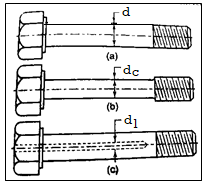
(Fig b) Reduce the shank diameter to the thread core diameter or less
(Fig c) Extend the length of the shank section.
The threaded portion of the bolt is the weakest, absorbing the greatest amount of elastic energy. The ideal bolt will be one in which the same stress level is applied to different cross-sections of the bolt. It's known as the bolt of uniform strength. The entire bolt is stressed to the same limiting value in a uniform strength bolt, resulting in maximum energy absorption.
There are two methods for reducing the cross-sectional area of the shank and converting an ordinary bolt into a uniform strength bolt.
Both methods reduce the cross-sectional area of the shank while increasing stress and energy absorption. The diameter of the shank is typically reduced to the core diameter of the threads in the first method. As a result, the cross-sectional area of the shank equals the cross-sectional area of the threaded portion. When this bolt is subjected to tensile force, the stress in the shank and the stress in the threaded portion are equal. In the second method, the diameter of the hole (d) is calculated by equating the cross-sectional area of the shank to that of the threaded part.


Here d is nominal or major diameter,  is core or minor diameters of threads,
 diamter of hole
Key Takeaway
The threaded portion of the bolt is the weakest, absorbing the greatest amount of elastic energy. The ideal bolt will be one in which the same stress level is applied to different cross-sections of the bolt. It's known as the bolt of uniform strength
To get uniform strength bolt
- Reduce the shank diameter to the thread core diameter or less
- Extend the length of the shank section

The threads on all screw fasteners meet the self-locking condition. The helix angle for metric threads with major diameters ranging from 6 to 68 mm ranges from 3°30' to 1°40'. The helix angle is much smaller than the friction angle. Furthermore, there is friction at the bearing surfaces of the nut and the bolt head. As a result, thread loosening between the bolt and nut should not occur under normal working conditions. Ordinary threaded fasteners retain their tightness in the presence of static loads. However, when subjected to cyclic and impact loads, many of these fasteners become loose. Loosening is caused by a decrease in friction force in the threads as a result of the bolt's consecutive expansion and contraction caused by fluctuating axial load. It is also caused by elastic vibrations along the screw's axis. Vibrations are the primary cause of thread loosening in many applications. Locking devices are used to keep the threads between the nut and the screw from loosening. Locking can be accomplished using one of three methods:
(i) by increasing friction; (ii) by using special locking devices such as split pins; and (iii) by plastic deformation.
In practice, a wide range of locking devices are available.
Jam nut
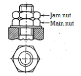
The most common method for locking the threads is to use a jam nut, which is a second nut, as shown in Figure. It is also known as a locknut. The thread-locking procedure consists of the following steps:
- The lower nut is tightened with normal force first.
- The upper nut is then tightened against the lower nut.
- A spanner is used to hold the upper nut, and another spanner is used to slacken the lower nut against it.
Tightening the lower nut against the upper nut's surface increases friction at the contacting interface. This friction force is independent of the external force acting on the joint. Following assembly, the upper nut, known as the jam nut, bears the majority of the axial load. Tightening and friction forces in the threads of the lower nut, also known as the main nut, are reduced. Even when the axial force on the bolt is removed, the joint remains tight due to friction between the surfaces of the two nuts.
Castle nut
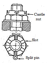
Another common method for obtaining positive thread locking is to use a castle nut with a split pin. Figure above depicts this. The castle nut is made up of a hexagonal nut with an upper cylindrical portion added. This cylindrical portion has six slots, one on each face of the hexagonal part. Castle nut is also known as a slotted nut because of its slots. A split pin is threaded through diametrically opposed slots in the castle nut and a bolt hole. Unless the pin is sheared, this ensures positive locking.
Split Nut
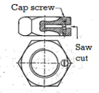
Figure shows a split nut. It is similar to a regular hexagonal nut, but with a saw cut in it. To tighten or loosen the two parts of the nut separated by the saw cut, a cap screw is provided. The nut is tightened on the screw first, and then the slot is opened with the cap screw. The opening of the slot causes the nut to deform and adds friction to the threads. This keeps the nut from loosening.
Locking with set Screw
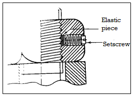
Figure shows a positive locking arrangement using a setscrew. The elastic band is made of a soft material such as copper or lead. When the setscrew is tightened in the nut, it protects the threads. This arrangement increases friction between the threads of the bolt and the elastic piece, preventing loosening.
Locking with washer

The use of a spring washer to lock threads is a common method of preventing thread loosening. The spring washer is made up of a hardened steel ring with a 15° cut with the ring axis. The ends of the washer that have been cut are slightly separated and have sharp teeth. The spring washer is compressed during tightening, and its teeth bite into the nut's contacting surface on one side and the base on the other. As a result, the nut is secured in the base. When the contacting surfaces are soft, the spring washer's action is more effective. The spring washer has a cut with a 'left-hand inclination for right-hand threads and a right-hand inclination for left-hand threads.
Key Takeaway
- Locking devices are used to keep the threads between the nut and the screw from loosening. Methods are Locking with washer, Locking with set Screw, Split Nut, Castle Nut, Jam nut
Bolted Joint
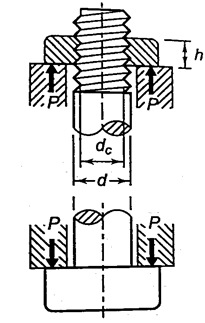
Bolted joint is subjected to tensile stress P, the maximum Tensile Stress is given by

The height of the nut h can be calculated by equating the bolt's tension strength with its shear strength. The following assumptions underpin the procedure:
- Each thread turn in contact with the nut supports the same amount of load.
- The threads do not have any stress concentrations.
- The yield strength in shear is half that of the tension yield strength (Ssy = 0.5Syt).
- Failure occurs in the bolt threads rather than the nut threads.

- Failure due to shear at core diameter, the shearing area is


From 1 and 2
 5
5
As a result, for standard coarse threads, if the nut height is approximately 0.4 times the nominal diameter of the bolt, the threads are equally strong in failure by shear and failure by tension. The standard hexagonal nut's height is (0.8d). As a result, the threads of the bolt in the standard nut will not shear.
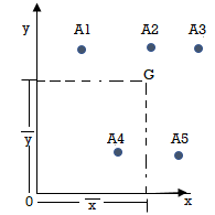
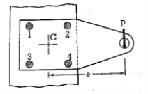
The bolts are frequently used in groups let A1, A2, A3, A4 be their areas of cross section
And Coordinates be (x1, y1), (x2, y2), (x3, y3), (x4, y4) are with respect to center G, So the center of gravity will be at (X, Y) as


The external force P with distance from origin ‘e’, is same as an imaginary force  acting at center of gravity which results in primary shear forces at bolt P1’, P2’, P3’, P4’ such that

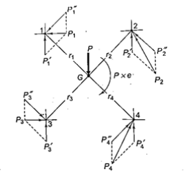
The moment  at center of gravity which results in secondary shear forces at bolt P1”, P2’’, P3’’, P4’’ with radial distances r1, r2, r3, r4, such that

Assuming that secondary forces are proportional to distance from center of gravity


Substitute in 1

Therefore, the secondary shear at any bolt can be calculate as


Key Takeaway
The secondary shear at any bolt can be calculate as

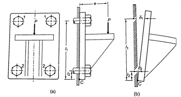
Consider a bracket bolted to a structure as shown in Figure. Let an eccentric force P be acting at a distance e from the structure. Lower two bolts are denoted by 2 and upper two by 1. P is acting perpendicular to the axes of the bolts and leads to a direct shear load, which can be given by,

Furthermore, due to eccentricity, P generates a moment  , which tends to tilt the bracket about the edge C. As a result, all of the bolts experience tensile forces that are proportional to their distance from C. If and are the resisting tensile forces developed in bolts at positions 1 and 2,

Using C as the proportionality constant,

By equating the moments caused by P and the resisting forces,


Bolts farthest from the tilting edge have the greatest resistance to tensile force. As a result, the bolts denoted by 1 will have maximum stresses, which can be calculated as follows: The maximum principal stresses developed in the bolts can then be determined and compared to the allowable values, or bolt dimensions for a given material can be determined.
Key Takeaway
The total tensile force in each bolt at positions 1 and 2 is given by for perpendicular eccentric load,

Consider the bracket bolted to the structure depicted in Figure. Consider an eccentric force P acting at a distance e from the bracket's edge C, which tends to tilt it. Each position has two bolts, numbered 1 and 2. Because P is acting parallel to the axes of the bolts in this case, the moment causes a primary tensile force and a secondary tensile force.
The primary tensile forces are represented by,

Because bolts at 1 are the furthest away from the edge around which the bracket tends to tilt, they develop the greatest amount of resisting force. At position 1, the maximum tensile stress in bolts is given by

Key Takeaway
The total tensile force in each bolt at positions 1 and 2 is given by for parallel eccentric load,
P1 =P'1 + P"2 and P2 = P'2 + P"2


A machine component is frequently made with a circular base that is fastened to the structure with bolts located on the circumference of a circle. This type of loading can be seen in the flanged bearings of machine tools and the structure of the pillar crane. Figure depicts a round flange bearing held together by four bolts (b). At a distance from the support, it is subjected to an external force P. Assumptions are made as follows:
- All bolts are the same.
- The structure and the bearing are both rigid.
- There is no tensile stress due to initial tightening because the bolts are not preloaded.
- The stress concentration in the threads is not taken into account.
- Dowel pins are used to relieve shear stresses on the bolts.
When the load tends to tilt the bearing about the point C, as shown in Fig, each bolt is stretched by an amount (δ) proportional to its vertical distance from the point C. As a result, the resisting force acting on any bolt as a result of the bearing's tilting tendency is proportional to its distance from the tilting edge.
Let P1, P2,P3 be the resting force
And P1 l1 or
l1 or
P1=Cl1, P2=Cl2, P3=Cl3, P4=Cl4 -----------------------------------1
Equating moment due force P about C with moment from resting forces
Pl= P1l1+P2l2+P3l3+P4l4------------------------------------------------------2
From 1 and 2

Therefore

Let a be radius of flange and b be pitch circle diameter of bolts
From Figure,


Therefore

This can be generalized for “n” number of bolts as

The Force will be Maximum, when  minimum that is

The equation gives the absolute maximum force acting on any of the bolts.
When the direction of the external force (P) can change with respect to the bolts (as in the case of the base of a vertical pillar crane). It should be used to determine the size of the bolts.
When the direction of the external force P is known, the maximum load on the bolts can be reduced, allowing the two to be equally stressed, as shown in Fig. The number of bolts in this case is four, and the angle a formed by the center line of bolt 2 is 135°. For the general case where n is the number of bolts.


Substituting value in


Only when two bolts are equally stressed can the above equation be used. This condition is met if
- The direction of the external force P is fixed with respect to the bolts
- The number of bolts is even
- Two bolts at the top are symmetrically spaced with angle ß on either side of the vertical line.
Key Takeaway
- Eccentric load on n no of bolts is

- Maximum load

Welding is the process of joining metallic parts by heating them to a suitable temperature with or without the application of pressure. Welding is a cost-effective and efficient way to create a permanent joint of metallic parts. Welded joints have two distinct applications. A welded joint can be used in place of a riveted joint, and a welded structure can be used as an alternative method of casting or forging.
Welded joints VS Riveted Joints
- Riveted joints necessitate the use of additional cover plates, gusset plates, straps, clip angles, and a large number of rivets, all of which add to the weight. Welded assembly results in lightweight construction because there are no such extra parts. Welded steel structures are 50% lighter than corresponding iron castings and 30% lighter than steel castings.
- The cost of welded assembly is lower than that of riveted joints due to the elimination of these components.
- Welded assemblies can be easily and affordably modified to meet changing product requirements. Welding allows for simple changes and additions to the existing structure.
- When compared to riveted assemblies, welded assemblies are more tight and leakproof. Welded assemblies have a shorter production time.
- When two parts are riveted together, holes in the parts are drilled to accommodate the rivets. The holes reduce the cross-sectional area of the members, which causes stress concentration. Welded connections do not have this issue.
- The appearance of a welded structure is smooth and pleasing. The projection of the rivet head has a negative impact on the appearance of the riveted structure.
- The welded joint has a high strength. The strength of the weld is frequently greater than the strength of the plates that are joined together.
Types of Weld Joints
Butt Joints
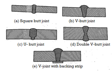
Butt joints and fillet joints are the two types of welded joints. A butt joint is a connection between two components that are roughly in the same plane. A butt joint connects the two plates' ends. Figure 1 depicts the various types of butt joints. The type of butt joint chosen is determined by the plate thickness and reliability. The following are some guidelines:
Plate Thickness (mm) | Butt Joint Type |
<5 | NO bevel, square joint |
5 to 25 | V shape joint |
20 to 30 | U joint |
>30 | Double V joint (with Backing strip |
Reliability of joints
Double V joint (with Backing strip) > Double V joint > V joint (with Backing strip) > V joint > Square
Fillet Joints
A fillet joint, also known as a lap joint, is a connection made between two overlapping plates or components. A fillet weld is made up of an approximately triangular cross-section that connects two surfaces that are at right angles to each other. As illustrated in Fig. 1, there are two types of fillet joints: transverse and parallel. If the direction of the weld is perpendicular to the direction of the force acting on the joint, the weld is called transverse. It is depicted in Fig. A single transverse fillet joint is not recommended because the unwelded edge of the plate can warp out of shape. In Fig., the lower plate's edge is free to deflect. As a result, a double transverse fillet weld, as illustrated in Fig, is preferred.
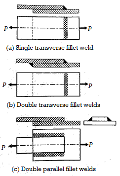
Parallel Fillet joint
If the direction of the weld is parallel to the direction of the force acting on the joint, the weld is called a parallel or longitudinal weld.
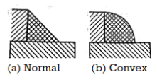
Normal Fillet joint and Convex Fillet Joint
The normal weld is made up of an isosceles triangle, which has two equal sides. A convex weld necessitates more filler material and labor. A convex weld has more stress concentration than a triangular weld. As a result, normal welds are preferred over convex welds.
Other Joints
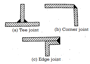
TEE Joints
A tee-joint is a joint formed by two components at right angles to each other in the shape of a T. In this case, a fillet weld is used to join the end face of one component to the side of the other component.
Corner joint
A corner joint is a connection made by two components that are at right angles to each other in the shape of an angle. A fillet weld is used to join the adjacent edges.
Edge joint
An edge joint connects the edges of two or more parallel components. It is applied to thin plates that are subjected to light loads.
Figure shows a butt welded joint subjected to tensile force P. σ= tensile stress in the weld (N/mm2) is the average tensile stress in the weld. P denotes the tensile force on the plates (N). h is the butt weld's throat (mm) And l denotes the length of the weld (mm)

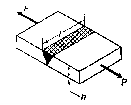
The weld throat does not include the bulge or reinforcement. The reinforcement is provided to compensate for weld flaws. Also, the height of weld will be equal to thickness of plate after welding.

The codes like unfired pressure vessel code suggest that strength of butt joints is reduce by factor of 

This is equation of strength for butt joints, where  is efficiency of joint. When properly made, a butt welded joint has equal or greater strength than plates, and there is no need to determine the stresses in the weld, as well as the size and length of the weld. All that is required is to match the weld material's strength to the strength of the plates
Key Takeaway
Strength of Butt joint is

Parallel Fillet joint
A tensile force P is applied to a parallel fillet weld. The dimensions of the fillet weld are denoted by two terms: leg h and throat t. The leg length determines the size of the weld. The fillet weld's cross-section is made up of a right-angled triangle with two equal sides. A leg is the length of each of the two equal sides. In general, the leg length h equals the plate thickness. The throat is the weld's smallest cross-section, located at 45° to the leg dimension. As a result, t = h cos (45°) t = 0.707 h
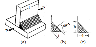
Shear along the minimum cross-section at the throat causes the fillet weld to fail.
Shear failure,

This is strength equation of fillet joint Usually the joint has two welds on either side so


Transverse Fillet joint
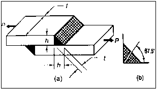
Tensile stress is applied to transverse fillet joints. The throat is the weld's smallest section. As a result, tensile stress failure will occur at the throat section. The throat's cross-sectional area is (tl). The transverse fillet weld's tensile stress is given by,

For transverse joint, t = h cos (45°) t = 0.707 h

This is strength equation of fillet joint. Usually, the joint has two welds on either side so


Key Takeaway
Strength of Transverse Fillet joint is

Strength of Parallel Fillet joint is

Unsymmetrical sections, such as angles or T, are welded to steel plates or beams in some applications. Figure depicts an angle section that has been welded to a vertical beam using two parallel fillet welds 1 and 2. G is the angle section's center of gravity. G is the path taken by the external force acting on the joint. Assume P1 and P2 are the resisting forces installed in welds 1 and 2, respectively.
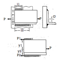
P1 = 0.707hl2
P2 = 0.707hl2
Figure depicts the free body diagram of forces acting on an angle section with two welds (b). Because the sum of horizontal forces equals zero, P= P1+ P2.
Because the moment of forces about the center of gravity is zero,
P1y1= P2 y2
0.707hl2 y1 =0.707hl2
 y2
y2
l2 y1 =l2y2
Also, l2 +l2 =l
Key Takeaway
- To solve
- Find l by using,

- By using l2 y1 =l2y2, find relation between them
- By substituting l and other find lengths
l2 +l2 =l
Calculations of primary and secondary shear stresses are used in the design of a welded joint subjected to an eccentric load in the plane of welds. Figure shows a bracket subjected to an eccentric force P and attached to a support by two fillet welds W1 and W2. The first step in such problems is to determine the center of gravity of welds by treating the weld as a line. Assume G is the center of gravity of two welds and e is the eccentricity between the center of gravity and the force P's line of action.
The eccentric force P can be replaced by an equal and similarly directed force (P) acting through the center of gravity G, along with a couple (M = P x e) lying in the same plane, according to the principle of Applied Mechanics.

Figure depicts the stresses in this welded joint. The direct shear stress in the welds is caused by the force P acting through the centre of gravity It is referred to as primary shear stress. The primary shear stress is assumed to be uniformly distributed across the throat area of all welds. A represents the throat area of all welds.
Torsional shear stresses are caused by the couple M in the throat area of welds. They are known as secondary shear stresses and are given by

r = the distance between two points in the weld. J denotes the polar moment of inertia of all welds about G.
To find Value of J
The moment of inertia about G is

That is Polar moment JG1

Since t << l,  ,
,


To find Polar moment with respect to G, Parallel axis theorem is used,


For n no of welds

Key Takeaway
Torsional shear stresses are caused by the couple M in the throat area of welds. They are known as secondary shear stresses and are given by

Where 

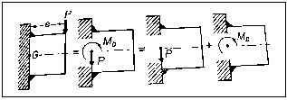
Two fillet welds W and W connect a rectangular cross-section cantilever beam to a support.
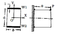
The eccentric force P can be replaced by an equal and similarly directed force P acting through the plane of welds, according to the principle of Applied Mechanics. As well as a couple (M = P x e), as shown in Fig. The primary shear stress  is caused by the force P through the plane of welds, which is given by

A represents the throat area of all welds. Bending stresses in the welds are caused by the moment Mb. Bending stresses are

To find the I, using parallel axis theorem

Since t << l

For two symmetrical welds

The resultant bending stress is

Key Takeaway
The resultant bending stress is

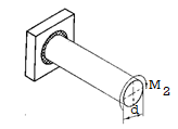
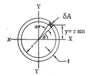

The circular shaft is welded circumferentially as shown. Mt is torsional moment induced. Let δA be area of elemental section with angle ϴ then δA is given by,
δA =r dϴ t
To find 

To find  integrating from 0 to

By Symmetry

Now

Torsional shear stresses

Key Takeaway
Weld Joint Subjected to Torsional Moment Relation is given by

References:
- Design of Machine Element VB Bhandari
- Machine Design RS Khurmi, JK Gupta