Unit - 6
Design of Springs
Spring
A spring is an elastic machine component that can deflect while under load. When you remove the load, it returns to its previous location. To put it another way, a spring is a mechanical device formed of a material with a high yield strength that can be used to restore elasticity. It's utilized in a variety of machines to absorb shocks or to prevent shocks and vibrations from being transferred to crucial machine components.
Types of springs and Application
1. Helical springs
Helical springs are the most often utilized springs. A coil is wrapped in this type of spring in such a way that it resembles a thread. Compression, extension, and torque forces are all carried by this sort of spring. Helical springs are categorized into four types based on the loading conditions. Torsion spring, Spiral spring, Compression helical springs, Tension helical springs
a. Torsion Springs

The load delivered to the coil in this sort of spring is a torque or twisting force. To put it another way, helical springs can store and release angular energy. Alternatively, these springs may be used to keep a system in place. The helical coil twists and then applies equivalent force in the opposite direction. Torsion springs are employed in applications that do not spin fully 360 degrees. The rotation of these springs is either clockwise or anticlockwise.
Applications
Rocker switches and door hinges are two examples of applications.
b. Spiral Springs

Spiral springs are frequently referred to as clock springs or constant force springs. This type of spring was made by wrapping a steel band around it several times. The force released by this sort of spring is constant. These springs are employed in machines that must rotate multiple times while also releasing the same amount of stress on a consistent basis. When a greater amount of force is necessary, these springs are used. Some of these springs have a thicker connection, allowing them to rotate at a faster rate.
Applications
Automotive seat recliners, window regulators, and DC motors all employ these types of springs.
c. Tension Springs
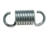
Extension Springs are another name for tension springs. Compression springs are the polar opposite of tension springs. The spring is extended as a result of the applied pull force. Hook or enlarged eyes can be found on one or both ends of these springs.
Applications
Lever mechanisms, weighing machines, and vise-grip pilers are some examples of applications.
d. Compression Springs
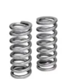
These are helical springs with an open coil. The load presses or squeezes a helical coil. It can withstand compressive and pushing forces. It also demonstrates linear compressive force resistance. Fluid pressure systems, for example, can act as compression springs.
Applications
Suspension on motorcycles, lock mechanisms.
2. Leaf Springs

Leaf springs are also known as cart springs or semi-elliptical springs. It is one of the most ancient types of spring. Leaf springs have a long, narrow, arc-shaped form. Vehicle suspensions use these sorts of springs. The axel is placed in the arc's centre. And the vehicle is attached to both ends of the loop. It disperses the load throughout the vehicle's chassis. Some advantages are Leaf springs are simple to put together. These springs have a lot of power
Applications
Automobile’s suspension systems. Leaf springs operate as a linkage, thus there's no need for a separate linkage to keep the axle in place. The rear axle's position aids in the reduction of unnecessary weight. Leaf springs influence the dampening of the axle. It saves money by not requiring a trailing arm or a pan hard rod.
3. Belleville spring
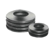
Coned-disc springs, conical spring washers, disc springs, Belleville washers, and cupped spring washers are all names for Belleville springs. The majority of Belleville washers are coin-shaped springs with a hole in the middle. The axis of this disc spring is loaded either dynamically or statically. This spring takes up less room to install yet can handle a lot of weight. In comparison to other springs, these springs provide additional benefits.
Applications
Slip and Overload Clutches, High Pressure Valve are examples of spring applications.
4. Conical and volute springs
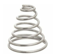
These are compression springs with a conical shape. Tapered springs are another name for conical springs. These springs were employed to enhance stability and lower the height of the solid.
Terminology of helical springs
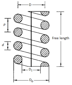
Here,
d = wire diameter of spring
 = inside diameter of the spring coil
 = outside diameter of the spring coil
 = mean coil diameter,
Spring index:
The spring index (C) is defined as the ratio of the mean coil diameter to the wire diameter.

The spring index determines how sharply the coil's curvature is curved. A low index indicates a high degree of curvature sharpness. Because of the curvature effect, when the spring index is low (C < 3), the real stresses in the wire are excessive. This type of spring is difficult to make, and great care must be used when coiling to avoid cracking in some wires. When the spring index is high (C > 15), the coil diameter varies dramatically. This type of spring is prone to buckling and tangles readily when handled. From a production standpoint, a spring index of 4 to 12 is regarded superior. As a result, the spring index in practical applications usually ranges from 4 to 12. However, for close tolerance springs and those subjected to cyclic loads, spring indexes in the range of 6 to 9 are still desirable.
Solid Length:
When the coils of a compression spring are compressed to the point of contact, the spring is said to be solid. The total number of coils multiplied by the wire diameter equals the solid length of a spring.

 = Total number of coils, and
d = Diameter of the wire.
Compressed Length:
The axial length of the spring that is subjected to maximal compressive force is known as compressed length. The spring is deflected to its maximum deflection in this situation. There should be some spacing or clearance between the adjacent coils when the spring is exposed to maximum force. The space is necessary to keep the coils from colliding. The clashing allowance, also known as the total axial gap, is typically calculated as 15% of the maximum deflection. In other cases, an arbitrary selection is made, and a gap of 1 or 2 mm between adjacent coils is assumed at maximum load conditions. Overall gap = (N-1) Gap between adjacent coils is the total axial gap in this example.
Free Length:
The free length of a compression spring refers to the length of the spring when it is not loaded. It's the solid length plus the spring's maximum deflection or compression, plus the clearance between adjacent coils (when fully compressed).


Pitch (p)
In an uncompressed state, pitch is defined as the axial distance between consecutive coils.

Spring Stiffness (k):
In an uncompressed state, pitch is defined as the axial distance between consecutive coils. The spring rate (also known as spring stiffness or spring constant) is defined as the load required per unit deflection of the spring.

Where,
k = spring stiffness (in N/mm) P denotes the axial spring force (N)
 = the spring's axial deflection in response to the force P (mm)
The stiffness of a spring is known by several names, including rate of spring, gradient of spring, scale of spring, and simply spring constant. The slope of the load-deflection line is represented by the spring stiffness.
Active and inactive coils
In a spring, active coils are coils that contribute to spring action, support external force, and deflect under force action. Inactive coils are a section of the end coils that is in touch with the seat but does not contribute to spring action. These coils do not support the load and do not deflect when a force is applied to them. The number of inactive coils is calculated as follows:

Here are total coils; N is no of active coils
According to seat the active coils in spring are calculated. Seating are square ends and square and ground ends, plain ends and plain and ground ends. The deflection determined by the load-deflection equation is unaffected by the turns at the two ends. As a result, the end turns should be removed from the overall number of turns when determining the number of active turns. For various end styles, the number of active turns is as follows:
Types of end | Active turns |
Plain ends |  |
Plain and ground ends | 
|
Square ends | 
|
Square and ground ends | 
|
Stress Equation
The load-stress equation and the load-deflection equation are the two essential equations for designing helical springs. Figure below shows a helical spring composed of circular cross-section wire (a). The mean coil diameter and wire diameter are D and d, respectively. This spring has a total of N active coils. An axial force P is applied to the spring. The helical spring's wire, when uncoiled and straightened, takes on the appearance of a bar, as seen in Fig. This bar is assumed to be equivalent to the actual helical spring when calculating the stress equation. The comparable bar's dimensions are as follows:
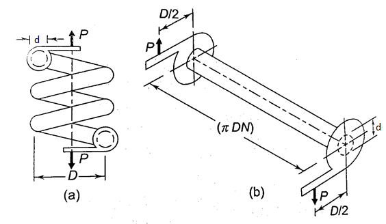
(i) The bar's diameter is the same as the wire's diameter.
(ii) One coil in the spring has a length of ( D). There are N active coils in total. As a result, the comparable bar's length is (
 DN).
DN).
(iii) A bracket is attached to each end of the bar. The length of this bracket is equal to the spring's mean coil radius (D/2).
The torsional shear stress in the bar is caused by the force P acting at the bracket's end. The torsional moment M is calculated as follows:

Torsional shear stress is given by


There are additional strains when the equivalent bar is twisted into a helical coil due to the following two factors:
(i) Shear stress is present in the form of direct or transverse shear stress the spring-loaded wire
(ii) The length of the inside fiber is shorter than the length of the outside fiber when the bar is bent into a coil.
As a result, tension is concentrated at the coil's interior fiber. The resultant stress is made up of torsional shear stress, direct shear stress, and extra stresses caused by the coil's curvature
The effect of direct shear stress and stress concentration owing to curvature effect are not taken into account in Equation (a). It has to be changed. To account for these consequences, we shall assume the following two factors:
Ks is a factor that takes into consideration direct shear stress Kc is a factor that takes into account the stress concentration caused by the curvature effect.
K=Kc, where K is the factor that accounts for the combined influence of two components, gives the combined effect of these two elements.
The bar's direct shear stress is given by,
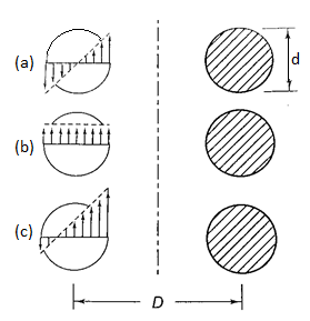

From 1 and 2, by superposition


Let 

Wahl derived the equation accompanying all factors Ks and Kc, that is given by

Here  is called Wahl Factor which is given by

Here C is spring constant
Deflection Equation
In normal application the springs are designed by using Wahl equation. The angle of twist is given by

Here  ,
,
l= DN,
DN,
J is polar moment  ,
,
G is modulus of rigidity
Therefore

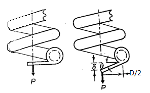
For very small values of  the axial deflection is given by
Therefore 


This equation is called load deflection equation
Strain Energy in spring
Load deflection equation is given by

Also, the rate of spring is

Therefore,

When a helical spring is sliced in half, the parameters G, d, and D remain the same, while N becomes (N/2). When N becomes (N/2) the stiffness (k) will be doubled.
That implies 
The load is proportional to the spring's deflection in a linear fashion. The strain energy stored in the spring is represented by the area below the load-deflection line. The energy stored in the spring is given by
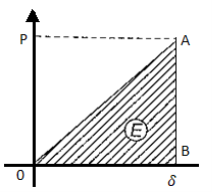
Assuming that the load is progressively applied.
E = area below load-deflection line
E= triangular area OAB
E

Key Takeaways
- Stress Equation

Here  is called Wahl Factor which is given by

- Deflection Equation

- Strain energy

The Springs can be arranged in series or parallel to achieve following
- To save the space
- To modify the spring rate at a specific deflection
- To create a fail-safe system.
Arrangement | Force | Deflection | Combined Stiffness |
Series 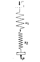 | Same on each spring and equal to external fore P  | Total deflection is sum of individual deflection  |  |
Parallel  | Force acting is combination of sum of forces acting individually  | Deflection in individual spring and combination is dame  |  |
Key Takeaways
Series or parallel arrangement is used to satisfy the space requirement, fail-safe systems.
For series arrangement

For parallel arrangement

1. For given application calculate spring force (P) and correspond required deflection . Calculate spring stiffness k =
 Either of above are specified for required.
2. Select suitable material for spring and calculate permissible shear stress using ultimate tensile strength


3. Select suitable spring Index C=(D/d)
C=8 to 10 typical
C =5 for valves, clutches
Also, C must be greater than 3
4. Calculate Wahl factor

5. Calculate Diameter of wire d

6. Calculate mean coil diameter D
D=Cd
7. Calculate No. Of Active turns
G is modulus of rigidity and for steel springs it is 81370N/mm2

8. Select the style and find inactive turns and total turns
Types of end | Active turns |
Plain ends |  |
Plain and ground ends | 
|
Square ends | 
|
Square and ground ends | 
|
Once  is known, inactive turn is

9. Determine the parameter of spring
- Solid length

- Actual Deflection

- Total axial Gap
Assume gap to be 0.5 to 2mm between adjacent coil
Total axial Gap = ( )
)
Or
Total axial Gap =0.15
- Free length of spring

- Pitch

- Spring Rate

10. Add Provision for Buckling if necessary
A helical compression spring that is too long in relation to the mean coil diameter works as a flexible column and can buckle at modest axial forces. The spring should ideally be built to resist buckling. Compression springs must be directed in a sleeve or over a harbour because they cannot be constructed to be buckle-proof. The following are the general guidelines for providing a guide:


A concentric spring is made up of two helical compression springs with the same axis, one inside the other. Figure depicts the situation. A 'nested' spring is also known as a 'concentric' spring. There are two springs in general. In other applications, however, concentric springs are made up of three coaxial springs: inner, middle, and outer springs. In Figure, two springs with opposite hands of helices are illustrated. The inner spring always has a left-hand helix if the outer spring has a right-hand helix, and vice versa. In the event of axial misalignment or buckling of springs, adjacent springs with opposing hands avoid coil locking.
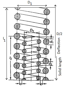
Advantages
The following are some of the benefits of a concentric spring:
- The weight carrying capacity is increased since there are two springs, and huge loads may be transmitted in a small space.
- In a concentric spring mechanism, even if one of the springs breaks, the system continues to function. As a result, the system is 'fail safe’.
- The spring vibrations known as 'surge' are minimized in concentric springs.
Applications
Heavy-duty diesel engines, aircraft engines, and railroad suspensions all use concentric springs as valve springs.
Analysis
- Maximum torsional shear stress is same


- Deflection of two springs are same


- Solid length is same

From equation c and b

Divide equation (d) by (a) we get

Divide equation (e) by (a) we get

That is

Therefore, load share by each spring is proportional to area
To account for diametrical expansion there is radial clearance given by c between diameters of concentric springs

This could be solved to get

Key Takeaways
A concentric spring is made up of two helical compression springs with the same axis, one inside the other.
This equation is used to design concentric springs

Resonance occurs when the inherent frequency of the spring's vibrations matches with the frequency of the external periodic force acting on it. The spring is subjected to a wave of sequential coil compressions that travels from one end to the other and back in this state. The 'surge' of spring refers to this type of vibratory action. Valve springs, which are subjected to periodic force, exhibit surge. Consider a helical compression spring with one end held against a hard flat surface and the other end subjected to a periodic external force. The transmission of this force from one end to the other always takes some 'time.' The force is delivered through coil compression. The end coil that comes into contact with the external force compresses first, then transfers a considerable percentage of its compression to the neighboring second coil. The second coil compresses, while the third coil receives the brunt of the compression. This process continues, and a wave of compressed coils travels the length of the spring until it reaches the end, where it is reflected back by a rigid surface. In interaction with the external force, the reflected wave travels back to the end. Resonance occurs when the time necessary for the wave to travel from one end to the other and back corresponds with the time interval between successive load applications of periodic external force, resulting in very large deflections of the coils and very high stresses. Many times, the stress in the coils exceeds the spring's endurance limit, resulting in fatigue failure. Surge is the most common cause of valve spring failure.
The natural frequency of helical compression springs maintained between two parallel plates can be calculated as follows

The natural frequency of helical compression springs maintained between one end on flat plate and other end free can be calculated as follows

Here K is stiffness
m is mass and m=Al
Methods to prevent Surge
Spring surges can be avoided by doing the following.
- The spring is constructed so that its natural frequency is 15 to 20 times that of the external force's excitation frequency. This avoids the occurrence of the resonance condition.
- Friction dampers are installed on the middle coils of the spring. Surge waves are prevented from propagating as a result of this.
- The surge is reduced with a stranded wire spring. The spring wire in this example is made up of three strands. While forming the spring, the strands are wound in the opposite direction as the coils are wound. When the coils are compressed, the spring tends to wind the individual wires closer together, causing friction. Surge is less likely with this frictional dampening.
Surge is a significant issue with common vibrations such as valve springs and firearms. In other applications where the external load is constant, this isn't an issue.
Key Takeaways
- The spring is subjected to a wave of sequential coil compressions that travels from one end to the other and back in this state at resonance. The 'surge' of spring refers to this type of vibratory action
- Surge is the most common cause of valve spring failure.
- Surge is a significant issue with common vibrations such as valve springs and firearms.
For the suspension of cars and railway carriages, multi-leaf springs are commonly employed. A multi-leaf spring is made up of several flat plates that are usually semi-elliptical in shape. The flat plates are known as spring leaves. The leaves are of varying lengths. The longest leaf is the one at the top. From the top to the bottom leaf, the length steadily diminishes. The master leaf is the topmost and longest leaf. Both ends are twisted away from the spring eyes. To secure the leaf spring to the car body, two bolts are placed through these eyes. Two U-bolts and a centre clip are used to hold the leaves together. The leaves are held in place by rebound clips, which keep them aligned and prevent lateral displacement during operation. The axle supports the leaf spring in the middle. In addition to the master leaf, multi-leaf springs have one or two additional full-length leaves. Between the master leaf and the graduated length leaves, the extra full-length leaves are stacked. The extra full-length leaves are there to support the shear force in the transverse direction. The leaves are separated into two groups for analysis: master leaf and graduated-length leaves in one group, and extra full-length leaves in the other.
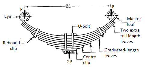
 = number of extra full-length leaves
 = number of graduated-length leaves including master leaf
n = total number of leaves
b=width of each leaf (mm)
t = thickness of each leaf (mm)
L-length of the cantilever or half the length of semi-elliptic spring (mm)
P= force applied at the end of the spring (N)
 portion of P taken by the extra full-length leaves (N)
 portion of P taken by the graduated-length leaves (N)
Sr no | Groups | Assumed Shape | Bending Stress in plate at support | Deflection at the load point | Figure |
1 | Master leaf and graduated-length leaves | Triangular plate with thickness t and maximum width (  |  |  |  |
2 | Extra full-length leaves | Rectangular plate with thickness t and uniform width (  |  |  |  |
Since the deflection between groups must be equal


Also  and
and  are portion of P, that is P=
  , using in equation (e) we will get


Substituting values in respective bending stresses that is equation (a) and (c), we get


It is clear that  by 50%, so the deflection equation is used to design is from group 1

This Equation is used to Design Multi leaf spring
Key Takeaway
The leaves are separated into two groups for analysis: master leaf and graduated-length leaves in one group, and extra full-length leaves in the other. After analysis this Equation is used to Design Multi leaf spring

Extra full-length leaves are subjected to 50 percent higher stress than graduated-length leaves. Pre-stressing the spring is one approach of balancing the stresses in different leaves. Pre-stressing is accomplished by bending the leaves to various curvature radii before assembling them with the centre clip. The full-length leaf has a larger radius of curvature than the adjacent leaf, as seen in Fig. With shorter leaves, the radius of curvature reduces. Before the construction, there is a nip between the extra full-length leaf and the graduated-length leaf C. Nipping is a term for pre-stressing achieved by a difference in curvature radii.
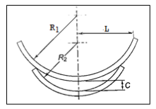
Pretension results in stress equalization is assumed


Also  and
and  are portion of P, that is P=


Deflection of graduated-length leaves will exceed the deflection of additional full-length leaves by an amount equal to the initial nip C when the maximum force P is applied.
From equation 1 and 2

Considering the first deflection of leaves, the initial pre-load P required to close the gap C between the extra full-length leaves and graduated length leaves is determined.


The extra full-length leaves' resultant stress is calculated by superimposing the stresses caused by the original pre-load (P) with the external force (P).

Deflection is same as without nipping

Key Takeaway
Nipping is a term for pre-stressing achieved by a difference in curvature radii to get in stress equalization
Nip

Pre tension

The external force acting on the spring fluctuates with time in a broad number of applications, resulting in fatigue failure. The fatigue crack usually starts with some surface irregularity and propagates due to tensile strains due to the spring wire's poor surface quality. Tensile stresses are always found to be the cause of fatigue crack growth. A layer of residual compressive stress is created on the spring wire's surface to limit the risks of crack propagation. Shot peening is one approach for producing such a layer. Small steel balls are impinged on the wire surface at high velocities, either by air blast or centrifugal force, in this process. When the balls collide with the wire surface, residual compressive stresses are created. The depth of the residual compressive stress layer is determined by a number of parameters, including the size of the balls, hitting velocity, original hardness, and ductility of the spring wire. These parameters are changed to provide the desired depth of compressive stress layer. For springs that are only loaded in one direction, such as helical compression, helical extension, or torsion bar springs, shot peening is effective.
Key Takeaway
- The external force acting on the spring fluctuates with time in a broad number of applications, resulting in fatigue failure Shot peening is one approach for producing such a layer of residual compressive stress on surface to limit the risks of crack propagation
References:
- Design of Machine Element VB Bhandari
- Machine Design RS Khurmi, JK Gupta