Unit - 4
Types of Heat Exchangers
Introduction
- A heat exchanger is device used for transfer of heat from high temperature fluid to low temperature fluid with both fluids moving through same device.
- Some of the key applications of heat exchangers are radiator in automobile, domestic water heater, evaporator and condenser in refrigerator and air-conditioners etc.
Classification of heat exchangers
Heat exchanger are classified based on
- Flow arrangements of fluid
- Heat transfer process
- Geometry of construction
A. Heat exchangers according to flow arrangements
I. Parallel flow heat exchanger:
- Both hot and cold fluid move in same parallel direction
- Also called concurrent flow heat exchanger
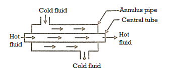
Fig1 Parallel flow heat exchanger
II. Counter flow heat exchanger:
- Both fluids flow in opposite directions.
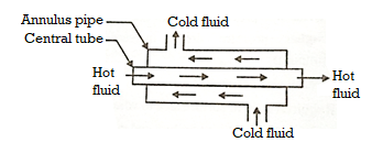
Fig2 Counter flow heat exchanger
III. Crossed flow heat exchanger:
- Two fluids flow in mutually perpendicular directions to each other.
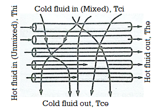
Fig3 Crossed flow heat exchanger
B. Heat exchangers according to heat transfer process
I. Direct contact type:
- Hot and cold fluids mix together and transfer of heat is by direct contact.
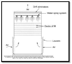
Fig4 Direct contact type heat exchangers
II. Transfer type heat exchanger:
- Heat is transferred between two fluids through metal surface between them.
- Also called as Recuperates.
- All parallel and counter flow heat exchangers are recuperates.
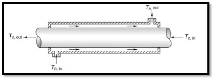
Fig5 Transfer type heat exchanger
III. Storage type heat exchanger:
- Hot and cold fluids flow alternatively on same flow passage called matrix.
- When hot fluid flows over matrix, it stores thermal energy. When cold fluid flows it gives away energy. Such energy transfer is called regeneration.
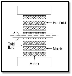
Fig6 Storage type heat exchanger
C. Heat exchangers according to geometry
I. Tube type heat exchanger:
- These are heat exchangers which contain tubes. Parallel and counter flow heat exchangers are example of this type of heat exchanger.
II. Shell and tube type heat exchanger:
- This are built up of round tubes mounted in large cylindrical shell with tubes parallel to shells.
- Heat transfer takes place as one fluid flows through the tube and other flows outside the tubes.
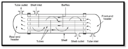
Fig7 Shell and tube type heat exchanger
III. Finned tube type heat exchanger:
- These are used as gas to liquid heat exchanger with high heat transfer rates.
- Fins are always added to gas side of various shapes.
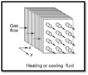
Fig8 Finned tube type heat exchanger
Temperature distribution in heat exchanger
Heat transfer takes place from hot to cold fluid in heat exchangers. The temperature of this liquid can be expressed as graphs as follows
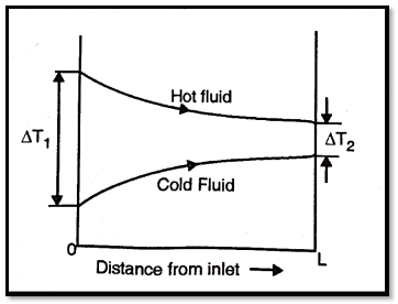
Fig9 Parallel flow heat exchanger
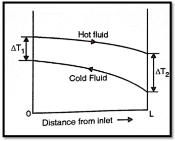
Fig10 Counter flow heat exchanger
Overall heat transfer coefficient and Fouling factor
If Thand Tcrepresent the bulk mean temperatures of the two fluids on either side of the plane wall, then

Where
1/UA = 
xw being the thickness of the wall, kw the thermal conductivity and h1 and h2 the heat transfer coefficients on the two sides.
As all the heat exchangers consist of tubes which are cylindrical in shape, for heat transfer through cylindrical wall
Q = U0A0(Th – Tc) = U0A0T
Where,  …(4.1)
A0 = π D0L,, Ai = π Di L, A1m= 
Equation (4.1) holds for clean surfaces on both sides of the cylindrical wall. During normal heat exchanger operation, surfaces are often subject to fouling by fluid impurities, rust formation, or other reactions between the fluid and the wall material. The subsequent deposition of a film or scale on the surface can greatly increase the resistance to heat transfer between the fluids. So that,

…(4.2)
Where hsi and hs0 are the scale heat transfer coefficients and Uo’ is the overall heat transfer coefficient with scaled surfaces. The reciprocal of the scale heat transfer coefficient is called the fouling factor Rf. Fouling factors which reduce the performance of heat exchangers can be determined experimentally
Rf = 1/U0 – 1/U0 …(4.3)
Log Mean Temperature Difference
- The temperature difference between two fluids is continuously changing from the inlet to the outlet of heat exchanger. This temperature difference must be averaged over the entire length of heat exchanger.
- Therefore, Log Mean Temperature Difference (LMTD) can be defined as the average temperature difference between hot and cold fluids over entire length of heat exchanger.
- LMTD helps in determining size and rate of heat transfer in heat exchanger.
Key Takeaways:
- Two fluids flow in mutually perpendicular directions to each other.
- Hot and cold fluids mix together and transfer of heat is by direct contact.
- All parallel and counter flow heat exchangers are recuperates.
- When hot fluid flows over matrix, it stores thermal energy. When cold fluid flows it gives away energy
- LMTD helps in determining size and rate of heat transfer in heat exchanger.
Parallel flow heat exchanger
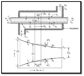
Fig11 Parallel flow heat exchanger
An insulated double pipe parallel flow heat exchanger along with the temperature profiles is shown in Fig. The temperatures of the fluids vary from point to point as heat is transferred from the hot to the cold fluid.
Let mh = mass flow rate of the hot fluid, kg/s
mc = mass flow rate of the cold fluid, kg/s
ch = specific heat of the hot fluid, kJ/kg K
cc = specific heat of the cold fluid, kJ/kg K
Th1 = inlet temperature of the hot fluid, oC
Th2 = exit temperature of the cold fluid, oC
Tc1 = inlet temperature of the cold fluid, oC
Tc2 = exit temperature of the cold fluid, oC
Let us consider a differential surface area d A0 (= D0 dx) of the heat exchanger where dQ amount of heat is transferred, the hot fluid temperature decreases by dTh and the cold fluid temperature increases by dTc. By writing an energy balance,
DQ = - 
…(4.4)
Where  T = Th – Tc, Th and Tc being the mean temperatures of the hot and cold fluids at that section respectively. This temperature difference
  T between the two fluids changes from
  Ti at inlet to
  Te at exit of the heat exchanger. Hence,
Ti = Th1 – Tc1 and Te = Th2 – Tc2
And
 …(4.5)
From 4.4 and 4.5
d(T) = -dQ/ - dQ /
= - dQ( 1/ + 1/
+ 1/ )
)
= - dQ μp
 …(4.6)
Where
μp = 1/ + 1/
+ 1/
By integrating 4.6 with  being constant
 …(4.7)
From 4.4 and 4.6
DQ = U0 dA0T
d(T)/μp = U0dA0 T
- 
Ln ( Ti/Te) = U0A0μp
…(4.8)
From Eq. 4.7 and 4.8
Ln Ti/Te = U0A0 
Q = U0 A0(T)lm = 
= 
Where, AT1m = (Ti - Te)/(ln Ti/Te)
= logarithmic mean temperature difference, or LMTD
And 
Counter flow heat exchanger
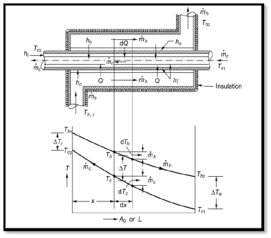
Fig12 Counter flow heat exchanger
Figure shows an insulated double pipe counter flow heat exchanger along with the temperature profiles. The energy balance for the differential surface area dA0 ( D0 dx) gives
DQ = - 
…(4.9)
Where both the hot and cold fluids undergo temperature decreases dTh and dTc (both being negative) in flowing the distance dx.

d(T) = dTh – dTc = dQ/
= - dQ ( 1/  )
)
= - dQ μc
…(4.10)
Where

By integrating 4.10 with  being constant
 …(4.11)
From 4.9 and 4.10
- d(T)/μp = U0dA0 T
- 
With U0 being assumed constant,
Ln ( Ti/Te) = U0A0μc
…(4.12)
From Eq. 4.11 and 4.12
Q = U0A0(T)1m
= 
= 
Where, T1m = (Ti - Te)/(ln Ti/Te) = LMTD
Ti = Th1 – Tc2 and Te = Th2 – Tc1
The Effectiveness-NTU method
To obtain the solution of this problem by the LMTD method, a trial-and-error approach has to be attempted. The method is quite tedious and can be avoided by following an alternative direct method called the effectiveness-NTU method.
The term effectiveness  of a heat exchanger is defined as

Let mh = mass flow rate of the hot fluid, kg/s
mc = mass flow rate of the cold fluid, kg/s
ch = specific heat of the hot fluid, kJ/kg K
cc = specific heat of the cold fluid, kJ/kg K
Th1 = inlet temperature of the hot fluid, oC
Th2 = exit temperature of the cold fluid, oC
Tc1 = inlet temperature of the cold fluid, oC
Tc2 = exit temperature of the cold fluid, oC
 …(4.13)
Where subscript “s” denotes the smaller of the two heat capacity rates  and
and  , or Cmin. The maximum possible heat transfer depends on one of the fluids undergoing the maximum possible change in temperature and that will be the fluid which will have the minimum value of heat capacity rate.
Thus, if 
 …(4.14)
And if 
 …(4.15)
Thus effectiveness can also defined as

Where  is larger of two temperature differences
  and
and  is maximum possible temperature rise or fall which is
Another important term in  -NTU method is heat capacity ratio. It is defined as ratio of minimum heat capacity rate to maximum heat capacity rate out of two fluids.
R =  …(4.16)
Where the subscripts “s” and “1” refer to the smaller and the larger of the two values of and
and  .
.
Value of  and R varies between 0 and 1.
Analysis of parallel flow heat exchanger
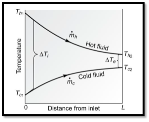
Fig13 Parallel flow heat exchanger
From Eq. 4.8
Ln Ti/Te = U0A0μp
Te/Ti = 
1 - Tc /Ti = 1 - 
But
Ti = Th1 – Tc1 and Te = Th2 – Tc2
Hence

Or,  …(4.17)


Eq. 4.17 becomes


 …(4.18)
Where NTU is number of transfer units and is equal to
NTU = 
( c)s or Cmin being equal to
  in this case. NTU gives a measure of the size of the heat exchanger.
Analysis counter flow heat exchanger
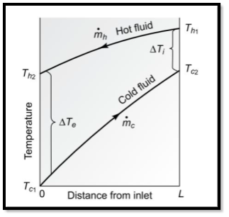
Fig14 Counter flow heat exchanger
From Eq.4.12
Ln Ti/Te = U0A0μc
Te/Ti = 
For counter flow heat exchanger

…(4.19)
Let, 
Then R = 
And 

…(4.20)
Also,

Hence 4.19 can be written as

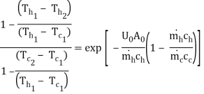

Let RHS=K

K - RK = 1 -
(1 – RK) = 1 – K
= (1 – K)/(1 – RK)

…(4.21)
Steps in analysis by Effectiveness-NTU method
The quantities  and
and  are computed.
If 

Then effectiveness of can found by Eq.4.18and 4.21
Since

From this  can be found out and
  can found by Eq.4.8
Special cases
- For R=0 (phase change heat exchanger)
Eq. 4.18 becomes
pf = 1 – exp (-NTU)
And Eq.4.21 becomes
ef = 1 – exp (- NTU)
- For R=1(balanced heat exchanger)
Eq. 4.18 becomes

And Eq.4.21 becomes

Selection of heat exchangers
Selection of heat exchangers depends on following criteria:
- Heat Transfer Rate
The fee of warmth go with the drift is the quantity of warmth this is transferred in step with unit of time in a few material, generally measured in watt (joules in step with second). Heat is the go with the drift of thermal power pushed through thermal non-equilibrium, so that 'warmth go with the drift' is a redundancy (i.e. a pleonasm, and the equal for ‘paintings go with the drift’). Heat have to now no longer be pressured with saved thermal power, and shifting a warm item from one location to every other have to now no longer be referred to as warmth transfer. But, regardless of most of these remarks, it's far not unusual place in everyday parlance to say ‘warmth go with the drift’, to speak of ‘warmth content’, etc.
- Cost
Ventilation warmness exchangers in farm animal’s barns lessen gasoline use through getting better warmness from exhaust air. The recovered warmness method much less gasoline is wanted to warmness the barn. Less gasoline use method decrease gasoline bills, which saves money
- Pumping Power
Pumping power is one piece of the puzzle this is crucial to consider. Pumping energy is calculated because the quantity of the fluid according to unit time (go with the drift capacity) instances the density of the fluid instances the gravitational consistent instances the pumping head (vertical distance to be pumped). Pumping power is truly energy elevated throughout time. As such, that is an crucial calculation due to the fact in case your device is designed in a manner that calls for excessive pumping speeds, you may have very excessive pumping power costs.
- Size and Weight
Door size
Exchanger size
Door assembly weight
Door heat removal capacity
| Air movement
Air source for servers
Air temperature drop
Air impedance
| Water source
Water pressure
Water volume
Water temperature
Required water flow rate (as measured at the supply entrance to the heat exchanger)
|
| ||
Table 1. Operating specifications for 19-inch EIA-rail heat exchanger
Type of heat exchanger required
Based at thelayouttraits indicated above, there are numerousuniqueversionsof warmth exchangers available. Some of the extranot unusual placeversionshiredat some point ofenterprise include:
- Shell and tube warmth exchangers
- Double pipe warmth exchangers
- Plate warmth exchangers
- Condensers, evaporators, and boilers
- Materials
There are numerous styles of additives which may be hired in warmth exchangers, in addition to a extensive variety of substances used to assemble them. The additives and substances used rely upon the sort of warmth exchanger and its supposed application. Some of the maximum not unusual place additives used to assemble warmth exchangers consist of shells, tubes, spiral tubes (coils), plates, fins, and adiabatic wheels. Further element on how those additives characteristic inside a warmth exchanger could be supplied with inside the subsequent section (see Types of Heat Exchangers).
Key Takeaways:
- To obtain the solution of this problem by the LMTD method, a trial-and-error approach has to be attempted.
- Another important term in
 -NTU method is heat capacity ratio. It is
 - But, regardless of most of these remarks, it's far not unusual place in everyday parlance to say ‘warmth go with the drift’, to speak of ‘warmth content’, etc
- Less gasoline use method decrease gasoline bills, which saves money
- Further element on how those additives characteristic inside a warmth exchanger could be supplied with inside the subsequent section (see Types of Heat Exchangers).
Heat switch enhancement in permeable tubes subjected to transverse suction glide is investigated on this work. Both momentum and electricity equations are solved analytically and numerically. Both answers primarily based totally on negligible access areas are nicely matched. Two unique suction speed distributions are considered.
A parametric take a look at such as the impact of the common suction speed and the suction speed profile is carried out for numerous Peclet numbers. It is located that enhancement of warmth switch over that during impermeable tubes is best feasible with big Peclet numbers. This enhancement will increase as suction velocities closer to the tube outlet boom and as the ones closer to the tube inlet lower simultaneously.
Numerical warmth switch is a large time period denoting the tactics for the solution, on a computer, of a fixed of algebraic equations that approximate the differential (and, occasionally, integral) equations describing conduction, convection and/or radiation warmth switch.
Numerical warmth switch is a huge time period denoting the strategies for the answer, on a pc, of a fixed of algebraic equations that approximate the differential (and, occasionally, necessary) equations describing conduction, convection and/or radiation warmth switch. The standard goal in any warmth switch calculation is the willpower of the fee of warmth switch to or from a few floor or object.
- In convection troubles, the temperature gradient in a fluid flowing over a floor is wanted to discover the warmth flux at that floor. In each cases, the willpower of the whole temperature distribution with inside the location of hobby is wanted as a primary step, and in convection one ought to additionally discover the rate distribution.
- Thus, a complete answer of the strength equation and possibly additionally the equations of movement is needed. These are partial differential equations, probably coupled. Radiation is particularly different, concerning surfaces separated (in trendy) via way of means of a fluid which might also additionally or might not take part with inside the radiation.
- If it's miles transparent, and if the temperatures of the surfaces are recognized, the radiation and convection phenomena are uncoupled and may be solved separately. If the floor temperatures aren't specified, however are to be located as a part of the answer, or if the fluid absorbs or emits radiant strength, then the 2 phenomena are coupled. In both case, the answer of the algebraic and/or necessary equations for radiation is needed similarly to that of the differential equations for convection and conduction.
- Thus analytical techniques, main to precise, closed shape solutions, are nearly continually now no longer available. Two procedures are viable. In the first, the equations are simplified — for example, via way of means of linearization, or via way of means of the overlook of phrases taken into consideration sufficiently small, or via way of means of the idea of regular residences, or via way of means of a few different approach till an equation or device of equations is received for which an analytical answer may be It can be stated that an precise analytical answer could be received for an approximate trouble.
- The mistakes can, in trendy, be envisioned and it could additionally be decreased on the fee of accelerated effort (which means accelerated pc time). It should now be stated that an approximate answer could be received for an precise trouble. In this entry, emphasis could be given to techniques for conduction and convection troubles, with simplest a quick point out of radiation.
- Attention could be restrained to incompressible fluids besides while buoyancy is important, wherein case the Boussinesq approximation could be made. The thoughts defined can frequently be utilized in greater trendy situations, however different techniques also are available, particularly for excessive pace flow, which might be past the prevailing scope.
Important Formulae
Overall heat transfer coefficient |  |
Overall heat transfer coefficient with fouling factor |  |
LMTD for parallel flow |  Where  |
LMTD for counter flow |  Where  |
Heat exchange by LMTD method | Q = U0A0(T)1m |
Effectiveness of parallel flow heat exchanger |  |
Effectiveness of counter flow heat exchanger |  |
Key Takeaways:
- Two unique suction speed distributions are considered.
- This enhancement will increase as suction velocities closer to the tube outlet boom and as the ones closer to the tube inlet lower simultaneously.
- The standard goal in any warmth switch calculation is the willpower of the fee of warmth switch to or from a few floor or object.
- In both case, the answer of the algebraic and/or necessary equations for radiation is needed similarly to that of the differential equations for convection and conduction.
- . In this entry, emphasis could be given to techniques for conduction and convection troubles, with simplest a quick point out of radiation.
References:
- Bejan, Heat Transfer John Wiley, 1993
- J.P.Holman, Heat Transfer, Eighth Edition, McGraw Hill, 1997.
- F.P.Incropera, and D.P. Dewitt, Fundamentals of Heat and Mass Transfer, John Wiley,Sixth Edition, 2007.
- MassoudKaviany, Principles of Heat Transfer, John Wiley, 2002
- Yunus A Cengel, Heat Transfer: A Practical Approach, McGraw Hill, 2002