Unit - 1
Conventional Manufacturing Processes
You likely don't spend much time thinking about who makes the products that fill your home. Albeit your business depends on makers, unless you pay time in a very plant, you most likely understand very little regarding the particular day-after-day work concerned. There are literally multiple varieties of processes a manufacturer uses, and people are classified into four main categories: casting and molding, machining, joining, and cut and forming.
Casting and Molding in Manufacturing:
If the products you’re making begin out as liquid, likelihood is that the manufacturer uses molding. One standard form of molding is casting, that involves heating plastic till it becomes liquid, then gushing it into a mould. Once the plastic cools, the mould is removed, supplying you with the required form. You'll be able to conjointly use casting to create plastic cloth, that encompasses a wide selection of applications. There are four alternative varieties of molding: injection molding, that melts plastic to form 3-D materials cherish butter tubs and toys; blow molding, accustomed build piping and milk bottles; compression molding, used for large-scale product like automotive tires; and motility molding, used for article of furniture and shipping drums.
Machining in Manufacturing:
It’d be troublesome to create product like metal components while not the employment of some form of machine. Makers use tools like saws, sheers and rotating wheels to attain the required result. There also are tools that use heat to form things. Optical device machines will cut a chunk of metal employing a high-energy ray, and plasma torches will flip gas into plasma exploitation electricity. Erosion machines apply an identical principle exploitation water or electricity, and pc numerical management machines introduce creating by mental acts into the producing combine.
Joining in Manufacturing:
You’ll be able to solely get to date with molds and machines. At some purpose you would like to be able to place multiple components along to create one piece. Otherwise, around all you'll be able to produce is IKEA-like article of furniture that has to be assembled, half by part. Change of integrity uses processes like fastening and bonding to use heat to mix materials. Items can even be joined exploitation adhesive bonding or fasteners.
Shearing and Forming in Manufacturing:
Once coping with flat solid, cut comes into play. cut uses cutting blades to create straight cuts into a chunk of metal. Conjointly referred to as die cutting, you’ll typically see cut used on aluminum, brass, bronze and stainless-steel. Another metal-shaping method is forming, that uses compression or another form of stress to maneuver materials into a desired form. though forming is usually used with metal, it can also be used on alternative materials, as well as plastic.
Casting could be a method during which liquified metal flows by gravity or alternative force into a mould wherever it solidifies within the form of the mold cavity. The term casting is additionally applied to the half that's created by this method. It's one in every of the oldest shaping processes, qualitative analysis back 6000 years. The principle of casting appears simple: soften the metal, pour it into a mould, and let it cool and solidify; however there are several factors and variables that has to be thought of so as to accomplish a triple-crown casting operation. Casting includes each the casting of ingots and also the casting of shapes. The term metal bar is sometimes related to the first metals industries; it describes an outsized casting that's easy in form and supposed for later reshaping by processes cherish rolling or formation. Form casting involves the assembly of additional advanced geometries that are a lot of nearer to the ultimate desired shape of the half or product.
Form of form casting ways are accessible, so creating it one in every of the foremost versatile of all producing processes. Among its capabilities and benefits are the following:
- Casting is accustomed produce advanced half geometries, as well as each external and internal shape.
- Some casting processes are capable of manufacturing components to web form. No more producing operations are required to attain the desired pure mathematics and dimensions of the components. Alternative casting processes are close to web form, that some further form process is needed (usually machining) so as to attain correct dimensions and details.
- Casting is accustomed manufacture terribly massive components. Castings deliberation quite one hundred tons are created.
- The casting method is performed on any metal which will be heated to the liquid state.
- Some casting ways are quite suited to production.
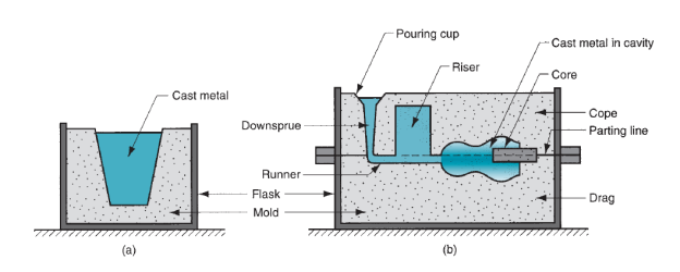
Figure 1: Two forms of mold: (a) open mold, simply a container in the shape of the desired part; and (b) closed mold, in which the mold geometry is more complex and requires a gating system (passageway) leading into the cavity.
There also are disadvantages related to casting, different disadvantages for various casting ways. These embody limitations on mechanical properties, porosity, poor dimensional accuracy and surface end for a few casting processes, safety hazards to humans once process hot liquefied metals, and environmental issues. Components created by casting processes place size from little elements deliberation solely many ounces up to terribly massive product weighing tons. The list of components includes dental crowns, jewelry, statues, wood-burning stoves, engine blocks and heads for automotive vehicles, machine frames, railway wheels, cookery pans, pipes, and pump housings. All types of metals is forged, ferric and nonferrous. Casting can even be used on alternative materials cherish polymers and ceramics.
The primary metal castings were created throughout the amount from 4000 to three000 B.C., exploitation stone and metal molds for casting copper. Varied casting processes are developed over time, every with its own characteristics and applications, to fulfill specific style necessities. An outsized form of components and elements are created by casting, cherish engine blocks, crankshafts, automotive elements and powertrains, agricultural and railroad instrumentality, pipes and plumbing fixtures, power-tool housings, gun barrels, cookery pans, jewelry, medical science implants, and extremely massive elements for hydraulic turbines. 2 trends have had a significant impact on the casting trade. The primary is that the mechanization and automation of the casting method, that has LED to vital changes within the use of apparatus and labor. Advanced machinery and automatic process-control systems have replaced ancient ways of casting. The second major trend has been the increasing demand for high-quality castings with shut dimensional tolerances. These classifications are involving mould materials, pattern production, molding processes, and ways of feeding the mold with liquified metal. The key classes are as follows:
- Expendable molds, which usually are fabricated from sand, plaster, ceramics, and similar materials and usually are mixed with varied binders (bonding agents) for improved properties. A typical sand mould consists of 90% sand, 7% clay, and 3% water, these materials are refractories (that is, they're capable of withstanding the high temperatures of liquified metals). Once the casting has solid, the mould is jerky to get rid of the casting. The mould is created from a pattern; in some processes, cherish sand and shell casting, the mould is expendable, and however the pattern is reused to provide many molds. Such processes are observed as expendable-mold, permanent-pattern casting processes. On the opposite hand, investment casting consumes a pattern for every mould produced; it's Associate in Nursing example of an expendable-mold, expendable pattern method.
- Permanent molds, that are fabricated from metals that maintain their strength at high temperatures. Because the name implies, they're used repeatedly and are designed in such the simplest way that the casting is removed simply and also the mould used for ensuing casting. Metal molds are higher heat conductors than expendable nonmetal molds; thence, the curing casting is subjected to a better rate of cooling that successively affects the microstructure and grain size at intervals the casting.
- Composite molds, that are fabricated from 2 or additional totally different materials (such as sand, graphite, and metal) combining the benefits of every material. These moulds have a permanent expendable portion and are utilized in varied casting processes to enhance mold strength, management the cooling rates, and optimize the social science of the casting method.
Sand-Casting Molds:
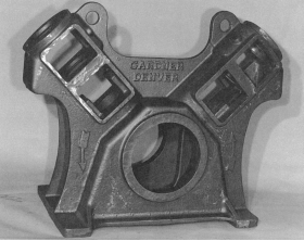
Figure 2: A large sand casting weighing more than 680 kg (1500 lb) for an air compressor frame.
Sand casting is far and away the foremost vital casting method. And-casting mould are going to be accustomed describe the essential options of a mold. Several of those options and terms are common to the molds utilized in alternative casting processes. Figure shows the cross-sectional read of a typical sand-casting mould, indicating a number of the nomenclature. The mould consists of 2 halves: cope and drag. The cope is that the higher half the mould, and also the drag is that the bottom. These 2 mould components are contained in a very box, known as a flask, that is additionally divided into 2 halves, one for the cope and also the alternative for the drag. The 2 halves of the mould separate at the parting line. In sand casting (and alternative expendable-mold processes) the mould cavity is made by means that of a pattern that is created of wood metal, plastic, or alternative material and has the form of the half to be forged. The cavity is made by packing sand round the pattern, regarding every within the cope and drag, in order that once the pattern is removed, the remaining void has the required form of the forged half. The pattern is sometimes created outsized to permit for shrinkage of the metal because it solidifies and cools. The sand for the mould is wet and contains a binder to take care of its form.
The cavity within the mould provides the external surfaces of the forged half. Additionally, a casting might have internal surfaces. These surfaces are determined by means that of a core, a type placed within the mould cavity to outline the inside pure mathematics of the half. In sand casting, cores are typically fabricated from sand, though alternative materials are used; cherish metals, plaster, and ceramics. The gating system in a very casting mould is that the channel or network of channels, by that liquefied metal flows into the cavity from outside the mould. As shown within the figure, the gating system generally consists of a down tropical sprue (also known as merely the sprue), through that the metal enters a runner that leads into the most cavities. At the highest of the down tropical sprue, a gushing cup is usually accustomed minimize splash and turbulence because the metal flows into the down tropical sprue. It's shown in our diagram as an easy conic funnel. Some gushing cups are designed within the form of a bowl, with Associate in Nursing open channel resulting in the down tropical sprue.
Additionally to the gating system, any casting during which shrinkage is important needs a riser connected to the most cavities. The riser could be a reservoir within the mould that is a supply of liquid metal for the casting to catch up on shrinkage throughout curing. The riser should be designed to freeze once the most casting so as to satisfy its operating. Because the metal flows into the mould, the air that antecedently occupied the cavity, moreover as hot gases fashioned by reactions of the liquefied metal, should be exhausted in order that the metal can utterly fill the empty house. In sand casting, as an example, the natural body of the sand mould permits the air and gases to flee through the walls of the cavity. In permanent metal molds, little vent holes are trained into the mould or machined into the parting line to allow removal of air and gases. The key options of molds in sand casting are as follows:
1. The flask, that supports the mould itself. Two-piece molds accommodates a cope on high and a problem on the bottom; the seam between them is that the parting line. Once quite 2 items are utilized in a sand mould, the extra components are known as cheeks.
2. A pouring basin or pouring cup, into that the liquefied metal is poured.
3. A sprue, through that the liquefied metal flows downward.
4. The runner system, that has channels that carry the liquefied metal from the tropical sprue to the mould cavity. Gates are the inlets into the mould cavity.
5. Risers, that offers further liquefied metal to the casting because it shrinks throughout curing.
6. Cores, that are inserts made up of sand. They’re placed within the mould to make hollow regions or otherwise outline the inside surface of the casting. Cores are also used on the skin of the casting to make options cherish inscription on the surface or deep external pockets.

Figure 3: Steps in the production sequence in sand casting. The steps include not only the casting operation but also pattern making and mold making.
Patterns and Cores:
Sand casting needs a pattern-a full-sized model of the half, enlarged to account for shrinkage and machining allowances within the final casting. Materials accustomed build patterns embody wood, plastics, and metals. Wood could be a common pattern material as a result of it's simply formed. Its disadvantages are that it tends to warp, and it's skinned by the sand being compacted around it, so limiting the amount of times it is reused. Metal patterns are dearer to create, however they last for much longer. Plastics represent a compromise between wood and metal. Choice of the suitable pattern material depends to an outsized extent on the whole amount of castings to be created. There are varied varieties of patterns, as illustrated in Fig. The only is created of 1 piece, known as a solid pattern-same pure mathematics because the casting, adjusted in size for shrinkage and machining. Though it's the best pattern to fabricate, it's not the best to use in creating the sand mould. Determinative the situation of the parting line between the 2 halves of the mould for a solid pattern is a haul, and incorporating the gating system and tropical sprue into the mould is left to the judgment and ability of the metalworks employee. Consequently, solid patterns are typically restricted to terribly low production quantities.
A Split pattern accommodates 2 items, dividing the half on a plane coinciding with the parting line of the mould. Split patterns are acceptable for advanced half geometries and moderate production quantities. The parting line of the mould is preset by the 2 pattern halves, instead of by operator judgment.

Figure 4: Types of patterns used in sand casting: (a) solid pattern, (b) split pattern, (c) match-plate pattern, and (d) cope-and-drag pattern.
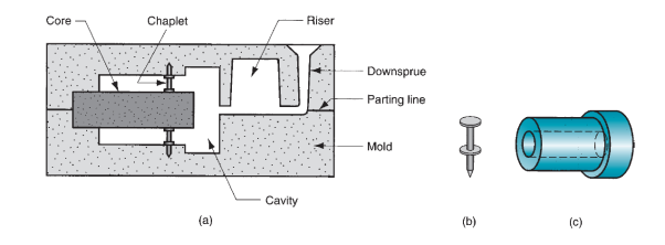
Figure 5: (a) Core held in place in the mold cavity by chaplets, (b) possible chaplet design, and (c) casting with internal cavity.
For higher production quantities, match-plate patterns or cope-and-drag patterns are used. In match-plate patterns, the 2 items of the split pattern are hooked up to opposite sides of a wood or metal plate. Holes within the plate enable the highest and bottom (cope and drag) sections of the mould to be aligned accurately. Cope and drag patterns are just like match-plate patterns except that split pattern halves are hooked up to separate plates, in order that the cope and drag sections of the mould is made-up severally, rather than exploitation an equivalent tooling for each. Half (d) of the figure includes the gating and riser system within the cope-and-drag patterns. Patterns outline the external form of the forged half. If the casting is to possess internal surfaces, a core is needed. A core could be a complete model of the inside surfaces of the half. It’s inserted into the mould cavity before gushing, in order that the liquefied metal can flow and solidify between the mould cavity and also the core to make the casting’s external and internal surfaces. The core is sometimes fabricated from sand, compacted into the required form. Like the pattern, the particular size of the core should embody allowances for shrinkage and machining. Looking on the pure mathematics of the half, the core might or might not need supports to carry it in position within the mould cavity throughout gushing. These supports, known as chaplets, are fabricated from a metal with a better melting temperature than the casting metal. As an example, steel chaplets would be used for forged iron castings. On gushing and curing, the chaplets become secure into the casting. A potential arrangement of a core in very mould exploitation chaplets is sketched in Figure. The portion of the garland projecting from the casting is afterwards stopping.
Molds and Mold Making:
Metalworks sands are silicon oxide (SiO2) or silica mixed with alternative minerals. The sand ought to possess sensible refractory properties-capacity to square up beneath high temperatures while not melting or otherwise degrading. Alternative vital options of the sand embody grain size, distribution of grain size within the mixture, and form of the individual grains. Little grain size provides a much better surface end on the forged half, however massive grain size is additional pervious (to enable escape of gases throughout pouring). Molds made up of grains of irregular form tend to be stronger than molds of spherical grains as a result of interlocking; however interlocking tends to limit porousness. In creating the mould, the grains of sand are control along by a mix of water and bonding clay. A typical mixture (by volume) is 90% sand, 3% water, and 7% clay. Alternative bonding agents is utilized in place of clay, as well as organic resins (e.g., synthetic resin resins) and inorganic binders (e.g., water glass and phosphate). Besides sand and binder, additives are typically combined with the mixture to reinforce properties cherish strength and/or porousness of the mould. To make the mould cavity, the normal methodology is to compact the molding sand round the pattern for each cope and involve a instrumentality known as a flask. The packing method is performed by varied ways. The only is hand ramming, accomplished manually by a metalworks employee. Additionally, varied machines are developed to mechanize the packing procedure. These machines operate by any of many mechanisms, as well as (1) compression the sand round the pattern by gas pressure; (2) a bumpy action during which the sand, contained within the flask with the pattern, is born repeatedly so as to pack it into place; and (3) a throw action, during which the sand grains are compact against the pattern at high speed.
An alternate to ancient flasks for every sand mould is flask less molding that refers to the employment of 1 master flask in a much mechanized system of mould production. Every sand mould is created exploitation an equivalent master flask. Mould production rates up to 600 per hour are claimed for this additional automatic methodology. Many indicators are accustomed confirm the standard of the sand mould (1) strength - the mold’s ability to take care of it form and resist erosion caused by the flow of liquefied metal; it depends on grain shape, adhesive qualities of the binder, and alternative factors; (2) porousness - capability of the mould to permit hot air and gases from the casting operation to go through the voids within the sand; (3) thermal stability - ability of the sand at the surface of the mold cavity to resist cracking and buckling upon contact with the liquefied metal; (4) collapsibility - ability of the mold to administer manner and permit the casting to shrink while not cracking the casting; it conjointly refers to the flexibility to get rid of the sand from the casting throughout cleaning; and (5) reusability - will the sand from the broken mold be reused to create other molds? These measures are typically incompatible; as an example, a mould with larger strength is a smaller amount foldable.
Sand molds are typically classified as green-sand, dry-sand, or skin-dried molds. Sandstone molds are fabricated from a mix of sand, clay, and water, the word inexperienced pertaining to the very fact that the mould contains wetness at the time of gushing. Green-sand molds possess sufficient strength for many applications, sensible collapsibility, sensible porousness, sensible reusability, and are the smallest amount high-priced of the molds. They’re the foremost wide used mould sort, however they're not only. Wetness within the sand will cause defects in some castings, looking on the metal and pure mathematics of the half. A dry-sand mould is created exploitation organic binders instead of clay, and also the mould is baked in a very massive kitchen appliance at temperatures starting from two hundred 0C to 320 0C (3920F to 6080F). Kitchen appliance baking strengthens the mould and hardens the cavity surface. A dry sand mould provides higher dimensional management within the forged product, compared to green-sand molding. However, dry-sand molding is dearer, and production rate is reduced as a result of drying time. Applications are typically restricted to medium and enormous castings in low to medium production rates. In a very skin-dried mould, the benefits of a dry-sand mould is part achieved by drying the surface of a green-sand mold to a depth of ten to 25mm (0.4–1 in) at the mould cavity surface, exploitation torches, heating lamps, or alternative means that. Special bonding materials should be value-added to the sand mixture to strengthen the cavity surface. The preceding mould classifications check with the employment of typical binders consisting of either clay-and-water or ones that need heating to cure. Additionally to those classifications, with chemicals secure molds are developed that aren't supported either of those ancient binder ingredients. a number of the binder materials utilized in these ‘‘no-bake’’ systems embody furane resins (consisting of aldehyde alcohol, urea, and formaldehyde), phenolics, and synthetic resin oils. No-bake molds are growing in quality because of their sensible dimensional management in high production applications.
To perform a casting operation, the metal should be heated to a temperature somewhat higher than its freezing point so poured into the mould cavity to solidify. During this section, we have a tendency to think about many aspects of those 2 steps in casting. Heating furnaces of assorted sorts are accustomed heat the metal to a liquefied temperature sufficient for casting. The warmth energy needed is that the sum of (1) the heat to boost the temperature to the freezing point, (2) the warmth of fusion to convert it from solid to liquid, and (3) the warmth to boost the liquefied metal to the required temperature for gushing. This will be expressed:

Where H = heat content needed to boost the temperature of the metal to the gushing temperature;
 Density, g/cm3 (lbm/in3);
Cs = weight specific heat for the solid metal, J/g-C (Btu/lbm-F);
Tm = melting temperature of the metal, 0C (0F);
To = starting temperature - usually ambient, 0C (0F);
Hf =heat of fusion, J/g (Btu/lbm);
Cl = weight specific heat of the liquid metal, J/g-C (Btu/lbm-F);
Tp = pouring temperature, 0C (0F);
V = volume of metal being heated, cm3 (in3).
Pouring the Molten Metal:
Once heating, the metal is prepared for gushing. Introduction of liquefied metal into the mould, as well as its flow through the gating system and into the cavity could be a essential step within the casting method. For this step to achieve success, the metal should flow into all regions of the mould before curing. Factors moving the gushing operation embody pouring temperature, gushing rate, and turbulence. The gushing temperature is that the temperature of the liquefied metal because it is introduced into the mould. What’s vital here is that the distinction between the temperature at gushing and also the temperature at that temperature reduction begins (the freezing point for a pure metal or the liquidus temperature for alloy). This temperature distinction is usually observed because the superheat. This term is additionally used for the number of warmth that has to be off from the liquefied metal between gushing and once curing commences.
Gushing rate refers to the meter rate at that the liquified metal is poured into the mould. If the speed is simply too slow, the metal can chill and freeze before filling the cavity. If the gushing rate is excessive, turbulence will become a significant drawback. Turbulence in fluid flow is characterized by erratic variations within the magnitude and direction of the rate throughout the fluid. The flow is agitated and irregular instead of swish and efficient, as in streamline flow. Flow ought to be avoided throughout gushing for many reasons. It tends to accelerate the formation of metal oxides which will become entrapped throughout curing, so degrading the standard of the casting. Turbulence conjointly aggravates mould erosion, the gradual eroding of the mould surfaces because of impact of the flowing liquefied metal. The densities of most liquefied metals are a lot of above water and alternative fluids we have a tendency to usually affect. These liquefied metals also are rather more with chemicals reactive than at temperature. Consequently, the damage caused by the flow of those metals within the mould is important, particularly beneath turbulent conditions. Erosion is very serious once it happens within the main cavity as a result of the pure mathematics of the forged part is affected.
Engineering Analysis of Pouring:
There are many relationships that govern the flow of liquid metal through the gating system and into the mould. A very important relationship is Bernoulli’s theorem that states that the additions of the energies (head, pressure, kinetic, and friction) at any 2 points in a very flowing liquid are equal. This will be written within the following form:

Where h = head, cm (in); p = pressure on the liquid, N=cm2 (lb/ in2);  = density, g/cm3 (lbm/in3); v = flow velocity; cm/s (in/sec); g = gravitational acceleration constant, 981 cm/s/s (32.2×12 = 386 in/sec/sec); and F = head losses due to friction, cm (in). Subscripts 1 and 2 indicate any two locations in the liquid flow.
Bernoulli’s equation is simplified in many ways that. If we have a tendency to ignore friction losses (to take care, friction can have an effect on the liquid flow through a sand mold), and assume that the system remains at gas pressure throughout, then the equation is reduced to

This can be accustomed confirm the rate of the liquefied metal at the bottom of the tropical sprue. Allow us to outline purpose one at the highest of the tropical sprue and point two at its base. If purpose two is employed because the reference plane, then the pinnacle at that time is zero (h2 = 0) and h1 is that the height (length) of the tropical sprue. Once the metal is poured into the gushing cup and overflows down the tropical sprue, its initial speed at the highest is zero (v1 = 0). Hence, Eq. More simplifies to

Which is resolved for the flow velocity:

Where v = the velocity of the liquid metal at the base of the sprue, cm/s (in/sec);
g = 981 cm/s/s (386 in/sec/sec); and h = the height of the sprue, cm (in).
Another relationship of importance throughout gushing is that the continuity law, that states that the quantity rate of flow remains constant throughout the liquid. The quantity flow is up to the rate increased by the cross-sectional space of the flowing liquid. The continuity law is expressed:

Where Q = volumetric flow rate, cm3/s (in3/sec); v = velocity as before;
A = cross-sectional area of the liquid, cm2 (in2); and also the subscripts check with any 2 points within the flow system. Thus, a rise in space leads to a decrease in speed, and contrariwise.
Above equations indicate that the tropical sprue ought to be tapered. Because the metal accelerates throughout its descent into the tropical sprue gap, the cross-sectional space of the channel should be reduced; otherwise, because the speed of the flowing metal will increase toward the bottom of the tropical sprue, air is aspirated into the liquid and conducted into the mould cavity. To forestall this condition, the tropical sprue is meant with a taper, in order that the quantity flow vA is that the same at the highest and bottom of the tropical sprue. Presumptuous that the runner from the tropical sprue base to the mould cavity is horizontal (and thus the pinnacle h is that the same as at the sprue base), then the quantity rate of flow through the gate and into the mould cavity remains up to vA at the bottom. Consequently, we are able to estimate the time needed to fill a mould cavity of volume V as

Where TMF = mold filling time, s (sec); V = volume of mold cavity, cm3 (in3); and Q = volume flow rate, as before. The mold filling time computed by Eq. Must be considered a minimum time. This is often as a result of the analysis ignores friction losses and potential constriction of flow within the gating system; so, the mould filling time are going to be longer than what's given by above Eq.
Solidification of Metals:
Once gushing into the mould, the liquefied metal cools and solidifies. During this section we have a tendency to examine the physical mechanism of curing that happens throughout casting. Problems related to curing embody the time for a metal to freeze, shrinkage, directional curing, and riser style. Curing involves the transformation of the liquefied metal into the solid state. The curing process differs looking on whether or not the metal could be a pure part or alloy.
Pure Metals: A pure metal solidifies at a relentless temperature up to its temperature that is that the same as its melting point. The melting points of pure metals are standard and documented. The particular temperature reduction takes time, known as the native curing time in casting, throughout that the metal’s heat of transformation of fusion is discharged into the encompassing mould. The whole curing time is that the time taken between gushing and complete curing.
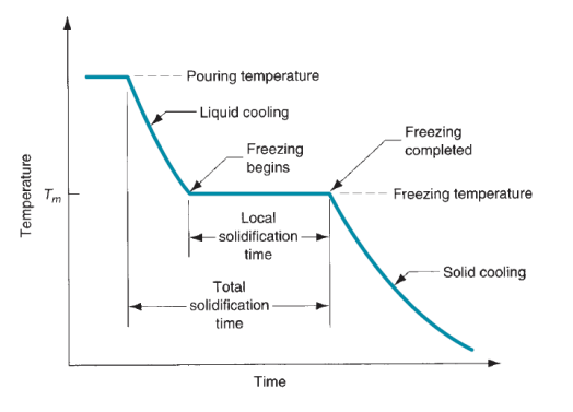
Figure 6: Cooling curve for a pure metal during casting.
Once the casting has utterly solid, cooling continues at a rate indicated by the downward slope of the cooling curve. As a result of the chilling action of the mould wall, a skinny skin of solid metal is at first fashioned at the interface like a shot once gushing. Thickness of the skin will increase to make a shell round the liquefied metal as curing progresses inward toward the middle of the cavity. The speed at that temperature reduction payoff depends on heat transfer into the mould, moreover because the thermal properties of the metal. It’s of interest to look at the aluminiferous grain formation and growth throughout this curing process. The metal that forms the initial skin has been chop-chop cooled by the extraction of warmth through the mould wall. This cooling action causes the grains within the skin to be fine and indiscriminately destined. As cooling continues, more grain formation and growth occur in a very direction removed from the warmth transfer. Since the warmth transfer is thru the skin and mould wall, the grains grow inside as needles or spines of solid metal. As these spines enlarge, lateral branches type, and as these branches grow, more branches type at right angles to the primary branches. This sort of grain growth is observed as nerve fiber growth, and it happens not solely within the temperature reduction of pure metals however alloys moreover. These dendroidal structures are bit by bit filled-in throughout temperature reduction, as further metal is frequently deposited onto the dendrites till complete curing has occurred. The grains ensuing from this nerve fibre growth combat a most popular orientation, tending to be coarse, columnar grains aligned toward the middle of the casting.
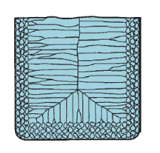
Figure 7: Characteristic grain structure in a casting of a pure metal, showing randomly oriented grains of small size near the mold wall, and large columnar grains oriented toward the center of the casting.
Most Alloys: Most alloys freeze over a temperature vary instead of at one temperature. The precise vary depends on the alloy system and also the specific composition.
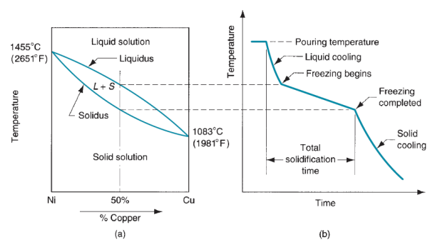
Figure 8: (a) Phase diagram for a copper– nickel alloy system and (b) associated cooling curve for a 50%Ni–50%Cu composition during casting.
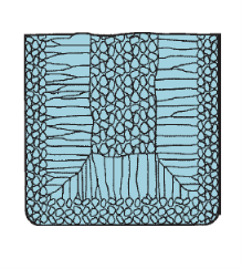
Figure 9: Characteristic grain structure in an alloy casting, showing segregation of alloying components in the center of casting.
Curing of alloy is explained with relevance figure that shows the part diagram for a specific alloy system and also the cooling curve for a given composition. As temperature drops, temperature reduction begin at the temperature indicated by the liquidus and is completed once the solidus is reached. The beginning of temperature reduction is comparable to it of the pure metal. A skinny skin is made at the mould wall because of the big gradient at this surface. Temperature reduction then progresses as before through the formation of dendrites that grow removed from the walls. However, attributable to the temperature unfold between the liquidus and solidus, the character of the nerve fiber growth is such Associate in Nursing advancing zone is made during which each liquid and solid metal exist. The solid parts are the nerve fiber structures that have fashioned sufficiently to entice little islands of liquid metal within the matrix. This solid–liquid region encompasses a soft consistency that has impelled its name because the mushy zone. Looking on the conditions of temperature reduction, the mushy zone is comparatively slender, or it will exist throughout, most of the casting. The latter condition is promoted by factors cherish slow heat transfer out of the new metal and a large distinction between liquidus and solidus temperatures. Gradually, the liquid islands within the nerve fiber matrix solidify because the temperature of the casting drops to the solidus for the given alloy composition.
Another issue complicating curing of alloys is that the composition of the dendrites as they begin to make favors the metal with the upper freezing point. As temperature reduction continues and also the dendrites grow, there develops Associate in Nursing imbalance in composition between the metal that has solid and also the remaining liquefied metal. This composition imbalance is finally manifested within the completed casting in the sort of segregation of the weather. The segregation is of 2 varieties, microscopic and gross. At the microscopic level, the chemical composition varies throughout every individual grain. This is often because of the very fact that the start spine of every nerve fiber encompasses a higher proportion of 1 of the weather within the alloy. Because the nerve fiber grows in its native neck of the woods, it should expand exploitation the remaining liquid metal that has been part depleted of the primary part. Finally, the last metal to freeze in every grain is that that has been cornered by the branches of the nerve fiber, and its composition is even more out of balance. Thus, we've got a variation in chemical composition at intervals single grains of the casting. At the gross level, the chemical composition varies throughout the complete casting. Since the regions of the casting that freeze initial (at the skin close to the mould walls) are richer in one part than the opposite, the remaining liquefied alloy is bereft of that part by the time temperature reduction happens at the inside. Thus, there's a general segregation through the crosswise of the casting, typically known as metal bar segregation, as illustrated in figure.
Eutectic Alloys: Eutectic alloys represent Associate in Nursing exception to the overall method by that alloys solidify. A mixture alloy could be a specific composition in Associate in Nursing alloy system that the solidus and liquidus are at an equivalent temperature. Hence, curing happens at a relentless temperature instead of over a temperature vary, as delineated higher than. The impact is seen within the part diagram of the lead–tin system shown in figure. Pure lead encompasses a freezing point of 3270C (6210F), while pure tin melts at 2320C (4500F). Though most lead–tin alloys exhibit the everyday solidus–liquidus temperature vary, the actual composition of sixty one.9% tin and thirty eight.1%lead encompasses a melting (freezing) purpose of 1830C (3620F). This composition is that the mixture composition of the lead–tin alloy system and 1830C is its mixture temperature. Lead–tin alloys aren't unremarkably utilized in casting; however Pb–Sn compositions close to the mixture are used for electrical bonding, wherever the low freezing point is a bonus. Samples of mixture alloys encountered in casting embody aluminum–silicon (11.6% Si) and forged iron (4.3% C).
Solidification Time:
Whether the casting pure metal or alloy, curing takes time. The whole curing time is that the time needed for the casting to solidify once gushing. This point depends on the scale form of the casting by an empirical relationship referred to as Chvorinov’s rule that states:

Where TTS total solidification time, min;
V = volume of the casting, cm3 (in3);
A = surface area of the casting, cm2 (in2);
n is an exponent usually taken to have a value = 2;
And Cm is the mold constant. Given that n = 2, the units of Cm are min/cm2 (min/in2), and it’s worth depends on the actual conditions of the casting operation, as well as mould material (e.g., heat, thermal conductivity), thermal properties of the forged metal (e.g., heat of fusion, heat, thermal conductivity), and gushing temperature relative to the freezing point of the metal. The worth of Cm for a given casting operation is supported experimental knowledge from previous operations meted out exploitation an equivalent mould material, metal, and gushing temperature, albeit the form of the half is also quite totally different. Chvorinov’s rule indicates that a casting with a better volume-to-surface space quantitative relation can cool and solidify additional slowly than one with a lower ratio. This principle is place to sensible use in planning the riser in a very mould. To perform its operate of feeding liquefied metal to the most cavity, the metal within the riser should stay in the liquid part longer than the casting. In alternative words, the TTS for the riser should exceed the TTS for the most casting. Since the mould conditions for each riser and casting are an equivalent, their mould constants are going to be equal. By planning the riser to possess a bigger volume-to-area quantitative relation, we are able to be fairly certain that the most casting solidifies initial which the consequences of shrinkage are decreased. Before considering however the riser could be designed exploitation Chvorinov’s rule, allow us to think about the subject of shrinkage that is that the reason why risers are required.
Our discussion of curing has neglected the impact of shrinkage that happens throughout cooling and temperature reduction. Shrinkage happens in 3 steps: (1) liquid contraction throughout cooling before solidification; (2) contraction during the natural process from liquid to solid, known as curing shrinkage; and (3) thermal contraction of the solid casting throughout cooling to temperature. The 3 steps are explained with relevance a cylindrical casting created in Associate in Nursing open mould, as shown in figure. The liquefied metal like a shot once gushing is shown partially (0) of the series. Contraction of the liquid metal throughout cooling from gushing temperature to temperature reduction temperature causes the peak of the liquid to be reduced from its beginning level as in (1) of the figure. The number of this liquid contraction is sometimes around zero.5%. Curing shrinkage, seen partially (2), has 2 effects. First, contraction causes an additional reduction within the height of the casting. Second, the number of liquid metal accessible to feed the highest center portion of the casting becomes restricted. This is often sometimes the last region to freeze, and also the absence of metal creates a void within the casting at this location. This shrinkage cavity is named a pipe by metalworks men. Once solid, the casting experiences more contraction tall and diameter whereas cooling, as in (3). This shrinkage is decided by the solid metal’s constant of thermal enlargement that during this case is applied in reverse to see contraction.
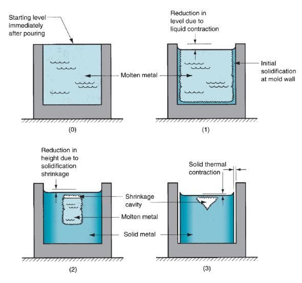
Figure 10: Shrinkage of a cylindrical casting during solidification and cooling: (0) starting level of molten metal immediately after pouring; (1) reduction in level caused by liquid contraction during cooling; (2) reduction in height and formation of shrinkage cavity caused by solidification shrinkage; and (3) further reduction in height and diameter due to thermal contraction during cooling of the solid metal. For clarity, dimensional reductions are exaggerated in our sketches.
Typical linear shrinkage values for different casting metals due to solid thermal contraction. | |||||
Metal | Linear Shrinkage | Metal | Linear Shrinkage | Metal | Linear Shrinkage |
Aluminum alloys | 1.3% | Magnesium | 2.1% | Steel, chrome | 2.1% |
Brass, yellow | 1.3%–1.6% | Magnesium alloy | 1.6% | Tin | 2.1% |
Cast iron, gray | 0.8%–1.3% | Nickel | 2.1% | Zinc | 2.6% |
Cast iron, white | 2.1% | Steel, carbon | 1.6%–2.1% |
|
|
Curing shrinkage happens in nearly all metals as a result of the solid part encompasses a higher density than the liquid phase. The part transformation that accompanies curing causes a discount within the volume per unit weight of metal. The exception is forged iron containing high carbon content, whose curing throughout the ultimate stages of temperature reduction is sophisticated by an amount of graphitization, which ends in enlargement that tends to counteract the meter decrease related to the natural process. Compensation for curing shrinkage is achieved in many ways that looking on the casting operation. In sand casting, liquid metal is equipped to the cavity by means that of risers. In die casting, the liquefied metal is applied fraught. Pattern-makers account for thermal contraction by creating the mould cavities outsized. The number by that the mould should be created larger relative to the ultimate casting size is named the pattern shrinkage allowance. Though the shrinkage is meter, the scale of the casting are expressed linearly, therefore the allowances should be applied consequently. Special ‘‘shrink rules’’ with slightly elongated scales are accustomed build the patterns and molds larger than the required casting by the suitable quantity. Table lists typical values of linear shrinkage for varied forged metals; these values is accustomed confirm shrink rule scales.
As delineated earlier, a riser is employed in a very sand-casting mould to feed liquid metal to the casting throughout temperature reduction so as to catch up on curing shrinkage. To operate, the riser should stay liquefied till once the casting solidifies. Chvorinov’s rule is accustomed reckon the scale of a riser that may satisfy this demand.
Varied defects will develop throughout producing that rely on factors cherish materials, half style, and process techniques. Whereas some defects have an effect on solely the looks of the components created, others will have major adverse effects on the structural integrity of the components. Many defects will develop in castings. As a result of totally different names are utilized in the past to explain an equivalent defect, the International Committee of metalworks Technical Associations has developed an identical word consisting of seven basic classes of casting defects, known with boldface capital letters:
A- Metallic projections, consisting of fins, flash, or projections cherish swells and rough surfaces.
B- Cavities, consisting of rounded or rough internal or exposed cavities as well as blowholes, pinholes, and shrinkage cavities.
C- Discontinuities cherish cracks, cold or hot tearing, and cold shuts. If the curing metal is unnatural from shrinking freely, cracking and tearing might occur. Though many factors are concerned in tearing, coarse grain size and also the presence of low-melting-point segregates on the grain boundaries (inter granular) increase the tendency for warm tearing. Cold shut is interface in a very casting that lacks complete fusion as a result of the meeting of 2 streams of liquid metal from totally different gates.
D- Defective surface, cherish surface folds, laps, scars, adhering sand layers, and compound scale.
E- Incomplete casting, cherish misruns (due to premature solidification), lean volume of the metal poured, and run out (due to loss of metal from the mould once pouring). Incomplete castings can also result from the liquefied metal being at too low a temperature or from pouring the metal too slowly.
F- Incorrect dimensions or shape, because of factors cherish improper shrinkage allowance, pattern-mounting error, irregular contraction, malformed pattern, or crooked casting.
G- Inclusions, that type throughout melting, solidification, and molding; these are typically nonmetal. They’re considered harmful as a result of they act as stress raisers and so cut back the strength of the casting. Inclusions might type throughout melting once the liquefied metal reacts with the atmosphere (usually oxygen) or with the vessel or mould material. Chemical reactions among elements within the liquefied metal itself might manufacture inclusions; slags and alternative foreign material entrapped in the molten metal conjointly become inclusions, though filtering will take away particles as little as thirty um. Finally, spilling of the mould and core surfaces will manufacture inclusions, so indicating the importance of the standard of molds and of their maintenance.
Residual Stresses:
“Internal” or “residual”, regardless of however we have a tendency to outline them, in a very metal material such stresses continually derive from some irregularity conditions within the fabric, irregularity that in castings is mostly including the very fact that the casting cooling doesn't occur at the same time altogether points, since the inner surface cools quicker than the fabric core, and also the zones with refined walls before the massive components. Generally terms “the residual stresses are generated within the part once irregularity components are gift within the science or material method characteristics”. Within the case of castings, aside from gross errors resulting in have homogeneity variations of the fabric among the varied zones of the half, the most supply of residual stresses is beyond any doubt the cooling method or, better, the non-simultaneous cooling among the varied zones of an equivalent part. Reminding of course that the particular volume of a metal material is directly proportional to temperature, it results that once the cooling of the external casting half happens, and internal half is implanted by high-temperature material.
Once the cooling extends to the fabric core, too, this may not shrink freely as a result of unnatural by the external solid surface: thus, we are going to have the external half stressed by compression by the core material, that in its flip are going to be stressed by traction by the external half. Analogue concerns are valid if the casting options components with totally different thickness, with components with refined stable walls before the parts with larger section, so the establishing of mutual traction or perhaps of deformations. We are able to thus state that the strain state in a very casting with refined walls has a minimum of 2 elements, one that we have a tendency to might outline “vertical” elicited by the interactions between the fabric on the surface and also the underlying material, and a “geometrical” one elicited by the constraints implanted by the encompassing material.
References:
1. Kalpakjian and Schmid, Manufacturing processes for engineering materials (5th Edition)-Pearson India, 2014.
2. Mikell P. Groover, Fundamentals of Modern Manufacturing: Materials, Processes, and Systems.
3. Manufacturing Technology by P.N. Rao., MCGRAW HILL INDIA.
4. Materials and Manufacturing by Paul Degarmo.
5. Manufacturing Processes by Kaushish, PHI.