Unit - 2
Introduction to bulk and sheet metal forming
Metal forming includes an outsized cluster of producing processes during which plastic deformation is employed to alter the form of metal work items. Deformation results from the employment of a tool, typically known as a die in metal forming, which applies stresses that exceed the yield strength of the metal. The metal thus deforms to require a form determined by the pure mathematics of the die.
Stresses applied to plastically deform the metal are typically compressive. However, some forming processes stretch the metal, whereas others bend the metal, and still others apply shear stresses to the metal. To be with success fashioned, a metal should possess bound properties. Fascinating properties embody low yield strength and high plasticity. These properties are stricken by temperature. Plasticity is hyperbolic and yield strength is reduced once work temperature is raised. The impact of temperature offers rise to distinctions between cold operating, heat operating and hot operating. Strain rate and friction are extra factors that have an effect on performance in metal forming. We have a tendency to examine all of those problems during this chapter, however 1st allow us to give a summary of the metal forming processes.
Metal forming processes may be classified into 2 basic categories: bulk deformation processes and sheet shaping processes. Every class includes many major categories of shaping operations, as indicated in Figure.
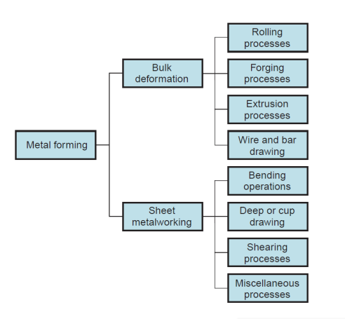
Figure 1: Classification of metal forming operations.
2.1.1 Bulk Deformation Processes:
Bulk deformation processes are typically characterized by important deformations and large form changes, and therefore the surface area-to-volume of the work is comparatively little. The term bulk describes the work elements that have this low space to- volume quantitative relation. Beginning work shapes for these processes embody cylindrical billets and rectangular bars. Figure illustrates the subsequent basic operations in bulk deformation:
Rolling: This can be a compressive deformation method during which the thickness of a block or plate is reduced by 2 opposing cylindrical tools known as rolls. The rolls rotate therefore on draw the work into the gap between them and squeeze it.
Forging: In formation, a work is compressed between 2 opposing dies, in order that the die shapes are imparted to the work. Formation is historically a hot operating method, however many varieties of formation are performed cold.
Extrusion: This can be a compression method during which the work metal is forced to flow through a die gap, thereby taking the form of the gap as its own cross section.
Drawing: During this forming method, the diameter of a spherical wire or bar is reduced by pull it through a die gap.
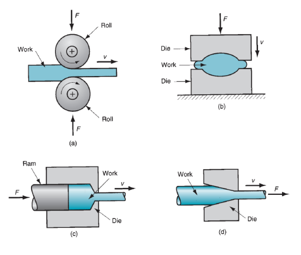
Figure 2: Basic bulk deformation processes: (a) rolling, (b) forging, (c) extrusion, and (d) drawing. Relative motion in the operations is indicated by v; forces are indicated by F.
2.1.2 Sheet Metalworking:
Sheet shaping processes are forming and cutting operations performed on metal sheets, strips, and coils. The surface area-to-volume quantitative relation of the beginning metal is high; so, this quantitative relation could be a helpful suggests that to differentiate bulk deformation from sheet processes. Press operating is that the term usually applied to sheet operations as a result of the machines accustomed perform these operations are presses (presses of assorted varieties are employed in different producing processes). Apart made in an exceedingly sheet operation is usually known as a stamping.
Sheet operations are perpetually performed as cold operating processes and are typically accomplished employing a set of tools known as a punch and die. The punch is that the positive portion and therefore the die is the negative portion of the tool set. The fundamental sheet operations are sketched are outlined as follows:
Bending:It involves straining of a metal sheet or plate to require an angle on a (usually) straight axis.
Drawing:In sheet shaping, drawing refers to the forming of a flat metal sheet into a hollow or incurvature, love a cup, by stretching the metal. A blank holder is employed to carry down the blank whereas the punch pushes into the sheet, as shown in Figure. To differentiate this operation from bar and wire drawing, the terms cup drawing or deep drawing are usually used.
Shearing:This method appears somewhat out-of-place in an exceedingly list of deformation processes, as a result of it involves cutting instead of forming. A cut operation cuts the work employing a punch and die, as in Figure. Though it's not a forming method, its enclosed here as a result of it is a necessary and really common operation in sheet shaping. The miscellaneous processes among the sheet shaping classification in Figure one embody a spread of connected shaping processes that don't use punch and die tooling. Samples of these processes are stretch forming, roll bending, spinning, and bending of tube stock.
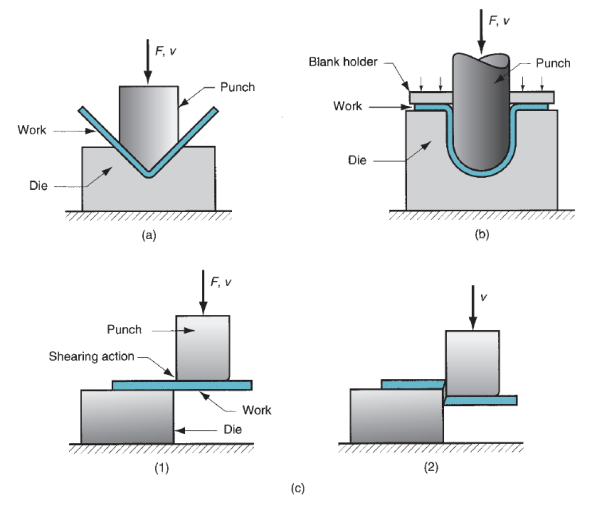
Figure 3: Basic sheet metalworking operations: (a) bending, (b) drawing, and (c) shearing: (1) as punch first contacts sheet, and (2) after cutting. Force and relative motion in these operations are indicated by F and v.
Sizable insight concerning the behavior of metals throughout forming may be obtained from the stress–strain curve. The standard stress–strain curve for many metals is split into Associate in Nursing elastic region and a plastic region. In metal forming, the plastic region is of primary interest as a result of the fabric is plastically and for good unshapely in these processes.
The standard stress–strain relationship for a metal exhibits snap below the yield purpose and strain hardening on top of it. Within the plastic region, the metal’s behavior is expressed by the flow curve:

Where K = the strength constant, MPa (lb/in2); and n is that the strain-hardening exponent. The strain σ and strain ϵ within the flow curve are true stress and true strain. The flow curve is mostly valid as a relationship that defines a metal’s plastic behavior in cold operating.
2.2.1 Flow Stress:
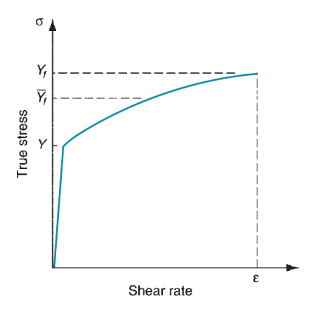
Figure 4: Stress–strain curve indicating location of average flow stress Yf in relation to yield strength Y and final flow stress Yf.
The flow curve describes the stress–strain relationship within the region during which metal forming takes place. It indicates the flow stress of the metal - the strength property that determines forces and power needed to accomplish a specific forming operation. For many metals at temperature, the stress-strain plot indicates that because the metal is unshapely, its strength will increase because of strain hardening. The strain needed to continue deformation should be hyperbolic to match this increase in strength. Flow stress is outlined because the instant worth of stress needed to continue deforming the fabric - to stay the metal ‘‘flowing.’’ it's the yield strength of the metal as perform of strain, which may be expressed:

Where Yf = flow stress, MPa (lb/in2).
Within the individual forming operations mentioned in the following 2 chapters, the instant flow stress may be accustomed analyze the method because it is happening. To illustrate, in bound formation operations, the instant force throughout compression may be determined from the flow stress worth. Most force may be calculated supported the flow stress that results from the ultimate strain at the tip of the formation stroke. In different cases, the analysis relies on the common stresses and strains that occur throughout deformation instead of instant values. Extrusion represents this case. Because the billet is reduced in cross section to go through the extrusion die gap, the metal bit by bit strain hardens to achieve a most worth. Instead of confirm a sequence of instant stress–strain values throughout the reduction, which might be not solely troublesome however conjointly of restricted interest, it's a lot of helpful to research the method supported the common flow stress throughout deformation.
2.2.2 Average Flow Stress:
The common flow stress (also known as the mean flow stress) is that the average worth of stress over the stress–strain curve from the start of strain to the ultimate (maximum) value that happens throughout deformation. The worth is illustrated within the stress-strain plot of Figure. The common flow stress is decided by group action the flow curve equation, between zero and therefore the final strain worth shaping the vary of interest. This yields the equation:

Where  = average flow stress, MPa (lb/in2); and ϵ = most strain worth throughout the deformation method. We have a tendency to build in depth use of the common flow stress in our study of the majority deformation processes within the following chapter. Given values of K and n for the work material, a way of computing final strain is developed for every method. Supported this strain, the eq. May be accustomed confirm the common flow stress to that the metal is subjected throughout the operation.
The flow curve could be a valid illustration of stress-strain behavior of a metal throughout plastic deformation, significantly for cold operating operations. For any metal, the values of K and n depend upon temperature. Strength and strain hardening are each reduced at higher temperatures. These property changes are vital as a result of the end in lower forces and power throughout forming. Additionally, plasticity is hyperbolic at higher temperatures that permit larger plastic deformation of the work metal. We are able to distinguish 3 temperature ranges that are employed in metal forming: cold, warm, and hot operating.
2.3.1 Cold Working:
Cold operating (also referred to as cold forming) is metal forming performed at temperature or slightly on top of. Important blessings of cold forming compared to hot operating are (1) larger accuracy, that means nearer tolerances may be achieved; (2) higher surface finish; (3) higher strength and hardness of the half because of strain hardening; (4) grain flow throughout deformation provides the chance for fascinating directional properties to be obtained within the ensuing product; and (5) no heating of the work is needed, that saves on chamber and fuel prices and permits higher production rates. Thanks to this mix of benefits, several cold forming processes became vital mass-production operations. They supply shut tolerances and sensible surfaces, minimizing the number of machining needed in order that these operations may be classified as internet form or close to net shape processes. There are bound disadvantages or limitations related to cold forming operations: (1) higher forces and power are needed to perform the operation; (2) care should be taken to confirm that the surfaces of the beginning work are freed from scale and dirt; and (3) plasticity and strain hardening of the work metal limit the number of forming that may be done to the half. In some operations, the metal should be treated so as to permit additional deformation to be accomplished. In different cases, the metal is just not ductile enough to be cold worked.
2.3.2Hot Working:
Hot operating (also known as hot forming) involves deformation at temperatures on top of the recrystallization temperature. The recrystallization temperature for a given metal is concerning common fraction of its freezing point on absolutely the scale. In observe, hot operating is typically applied at temperatures somewhat on top of 0.5Tm. The work metal continues to melt as temperature is hyperbolic on the far side 0.5Tm, so enhancing the advantage of hot operating on top of this level. However, the deformation method itself generates heat that will increase work temperatures in localized regions of the half. This could cause melting in these regions, which are extremely undesirable. Also, scale on the surface is accelerated at higher temperatures. Consequently, hot operating temperatures are typically maintained among the vary 0.5Tm to 0.75Tm. The foremost important advantage of hot operating is that the capability to supply substantial plastic deformation of the metal - way more than is feasible with cold working or heat working. The principal reason for this can be that the flow curve of the hot-worked metal incorporates a strength constant that's considerably lower than at temperature, the strain-hardening exponent is zero (at least theoretically), and therefore the plasticity of the metal is considerably hyperbolic. All of this ends up in the subsequent blessings relative to cold working: (1) the form of the work half may be considerably altered, (2) lower forces and power are needed to deform the metal, (3) metals that sometimes fracture in cold operating may be hot fashioned, (4) strength properties are typically identical attributable to the absence of the homeward grain structure usually created in cold operating, and (5) no strengthening of the half happens from work hardening. This last advantage could seem inconsistent, since strengthening of the metal is usually thought-about a plus for cold operating.
The majority deformation processes coated are (1) rolling, (2) formation, (3) extrusion, and (4) wire and bar drawing.
2.4.1 Rolling:
Rolling could be a deformation method during which the thickness of the work is reduced by compressive forces exerted by 2 opposing rolls. The rolls rotate as illustrated in figure to drag and at the same time squeeze the work between them. The fundamental method shown in our figure is flat rolling, accustomed scale back the thickness of an oblong cross section. A closely connected method is form rolling, during which a sq. Cross section is made into a form of I-beam.
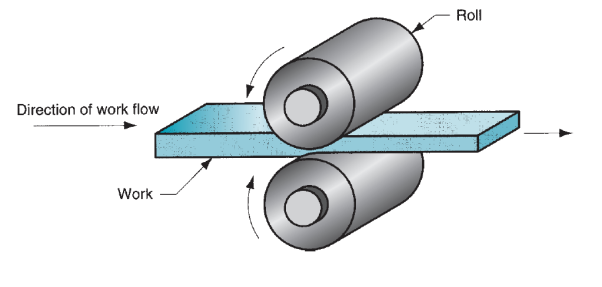
Figure 5: The rolling process (specifically, flat rolling).
Load Estimation for Flat Rolling:
Flat rolling involves the rolling of slabs, strips, sheets, and plates – work elements of rectangular cross section during which the dimension is larger than the thickness. In flat rolling, the work is squeezed between 2 rolls in order that its thickness is reduced by quantity known as the draft:

Where d = draft, mm (in);  = starting thickness, mm (in); and
  =final thickness, mm (in). Draft is typically expressed as a fraction of the beginning stock thickness, known as the reduction:

Where r = reduction. Once a series of rolling operations are used, reduction is taken because the sum of the drafts divided by the initial thickness. Additionally to thickness reduction, rolling typically will increase work dimension. This can be known as spreading, and it tends to be most pronounced with low width-to-thickness ratios and low coefficients of friction. Conservation of matter is preserved, that the volume of metal exiting the rolls equals the amount getting into.

Where w_0 and w_f are the before and once work widths, millimeter (in); and L_0 and L_(f )are the before and once work lengths, mm (in). Similarly, before and once volume rates of fabric flow should be constant, that the before and once velocities may be related:

Where  and
and  are the entering and exiting velocities of the work.
The rolls contact the work on Associate in Nursing arc outlined by the angle u. Every roll has radius R, and its movement speed offers it a surface speed volt-ampere. This speed is larger than the getting into speed of the work v_0 and fewer than its exiting speed very low frequency. Since the metal flow is continuous, there's a gradual amendment in speed of the work between the rolls. However, there's one purpose on the arc wherever work speed equals roll velocity. This can be known as the no-slip purpose, conjointly referred to as the neutral purpose. On either aspect of now, slippery and friction occur between roll and work. The number of slip between the rolls and therefore the work may be measured by suggests that of the forward slip; a term employed in rolling that's defined:

Where s = forward slip; v_f = final (exiting) work speed, m/s (ft/sec); and v_r = roll speed, m/s (ft/sec). Verity strain fully fledged by the some rolling relies on before and after stock thicknesses. In equation kind,

The true strain may be accustomed confirm the common flow stress Y ̅_f applied to the work material in flat rolling.

The average flow stress is employed to figure estimates of force and power in rolling.
Friction in rolling happens with an exact constant of friction, and therefore the compression force of the rolls, increased by this constant of friction, ends up in a friction force between the rolls and therefore the work. On the doorway aspect of the no-slip purpose, friction force is in one direction, and on the opposite aspect it's within the wrong way. However, the 2 forces don't seem to be equal. The friction force on the doorway aspect is larger, in order that cyberspace force pulls the work the rolls. If this weren't the case, rolling wouldn't be attainable. There’s a limit to the utmost attainable draft that may be accomplished in flat rolling with a given constant of friction, outlined by:

Where  = maximum draft, mm (in); m = coefficient of friction; and R = roll radius mm (in). The equation indicates that if friction were zero, draft would be zero, and it might be not possible to accomplish the rolling operation. Constant of friction in rolling depends on lubrication, work material, and dealing temperature. In cold rolling, the worth is around 0.1; in heat operating, a typical worth is around 0.2; and in hot rolling, µ is around 0.4. Hot rolling is usually characterized by a condition known as protrusive, during which the new surface adheres to the rolls over the contact arc. This condition usually happens within the rolling of steels and high-temperature alloys. Once protrusive happens, the constant of friction may be as high as 0.7. The consequence of protrusive is that the surface layers of the work are restricted to maneuver at constant speed because the roll speed vr; and below the surface, deformation is a lot of severe so as to permit passage of the piece through the roll gap. Given a constant of friction sufficient to perform rolling, roll force F needed to keep up separation between the 2 rolls may be computed by group action the unit roll pressure over the roll-work contact space. This could be expressed:

Where F = rolling force, N (lb); w = the width of the work being rolled, mm (in); p = roll pressure, MPa (lb/in2); and L = length of contact between rolls and work, mm (in). The combination needs 2 separate terms, one for either aspect of the neutral purpose. Variation in roll pressure on the contact length is important. a way of this variation may be obtained from the plot. Pressure reaches a most at the neutral purpose, and trails off on either aspect to the doorway and exit points. As friction will increase, most pressure will increase relative to entrance and exit values. As friction decreases, the neutral purpose shifts removed from the doorway and toward the exit so as to keep up a net pull force within the direction of rolling. Otherwise, with low friction, the work would slip instead of pass between the rolls. Associate in Nursing approximation of the results obtained by equivalent. May be calculated supported the common flow stress fully fledged by the work material within the roll gap. That is,

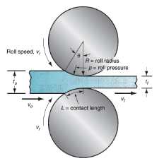
Figure 6: Side view of flat rolling, indicating before and after thicknesses, work velocities, angle of contact with rolls, and other features.
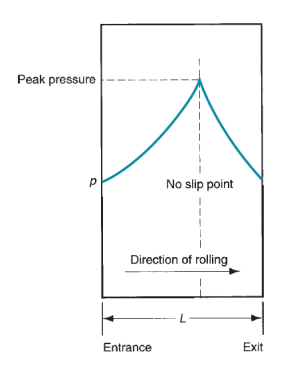
Figure 7: Typical variation in pressure along the contact length in flat rolling. The peak pressure is located at the neutral point. The area beneath the curve, representing the integration in above equation, is the roll force F.
Where  = average flow stress, MPa (lb/in2); and the product wL is the roll-work contact area, mm2 (in2). Contact length may be approximated by,

The torque in rolling may be calculable by assumptive that the roll force is targeted on the work because it passes between the rolls, which it acts with an instant arm of common fraction the contact length L. Thus, force for every roll is

The power needed to drive every roll is that the product of force and angular speed. Angular speed is 2πN, wherever N = movement speed of the roll. Thus, the facility for every roll is 2πNT. Substituting in eq. For torque during this expression for power, and doubling the worth to account for the very fact that a steelworks consists of 2 steam-powered rolls, we have a tendency to get the subsequent expression:

Where P = power, J/s or W (in-lb/min); N = rotational speed, 1/s (rev/min); F = rolling force, N (lb); and L = contact length, m (in).
2.4.2 Forging:
Forging could be a deformation method during which the work is compressed between 2 dies, mistreatment either impact or gradual pressure to create the half. It’s the oldest of the metal forming operations, geological dating back to maybe 5000 BCE. Today, forging is a crucial process accustomed build a spread of high-strength elements for automotive, aerospace, and different applications. These elements embody engine crankshafts and connecting rods, gears, craft structural elements, and reaction engine rotary engine elements. Additionally, steel and different basic metals industries use forging to determine the fundamental style of massive elements that are after machined to final form and dimensions. Another distinction among forging operations is that the degree to that the flow of the work metal is affected by the dies. By this classification, there are 3 styles of forging operations:
(a) Open-die forging,
(b) Impression-die forging, and
(c) Flashless forging.
In open-die forging, the work is compressed between 2 flat (or virtually flat) dies, so permitting the metal to flow while not constraint in an exceedingly lateral direction relative to the die surfaces. In impression-die forging, the die surfaces contain a form or impression that's imparted to the work throughout compression, so confining metal flow to a big degree. During this sort of operation, some of the work metal flows on the far side the die impression to create flash, as shown within the figure. Flash is excess metal that has got to be cut off later. In flashless forging, the work is totally affected among the die and no excess flash is made. The amount of the beginning work should be controlled terribly closely in order that it matches the volume of the die cavity.
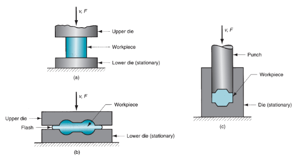
Figure 8: Three types of forging operation illustrated by cross-sectional sketches: (a) open-die forging, (b) impression-die forging, and (c) flashless forging.
Open-Die Forging:
The only case of open-die forging involves compression of a workpart of cylindrical cross section between 2 flat dies, a lot of within the manner of a compression check. This forging operation, referred to as disconcerting or upset forging, reduces the peak of the work and will increase its diameter.
Analysis of Open-Die Forging:
If open-die forging is applied below ideal conditions of no friction between works and die surfaces, then homogenized deformation happens, and therefore the radial flow of the fabric is uniform throughout its height. Below these ideal conditions, verity strain fully fledged by the work throughout the method may be determined by

Where  = starting height of the work, mm (in); and h = the height at some intermediate point in the process, mm (in). At the tip of the compression stroke, h = its final value
 , and therefore the true strain reaches its most worth.
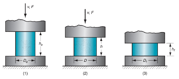
Figure 9: Homogeneous deformation of a cylindrical workpart under ideal conditions in an open-die forging operation: (1) start of process with workpiece at its original length and diameter, (2) partial compression, and (3) final size.
Estimates of force to perform disconcerting may be calculated. The force needed to continue the compression at any given height h throughout the method may be obtained by multiplying the corresponding cross-sectional space by the flow stress:

Where F = force, lb (N); A = cross-sectional area of the part,mm2 (in2); and  = flow stress corresponding to the strain given by Eq. MPa (lb/in2). Area A endlessly will increase throughout the operation as height is reduced. Flow stress Y_(f )conjointly will increase as a results of work hardening, except once the metal is absolutely plastic (e.g., in hot working). During this case, the strain-hardening exponent n = zero, and flow stress Y_f equals the metal’s yield strength Y. Force reaches a most worth at the tip of the formation stroke, once each space and flow stress are at their highest values. Associate in Nursing actual disconcerting operation doesn't occur quite as shown in figure as a result of friction opposes the flow of labor metal at the die surfaces, this creates the barreling impact. Once performed on a hot work dispense with cold dies, the barreling impact is even a lot of pronounced. This results from a better constant of friction typical in hot operating and warmth transfer at and close to the die surfaces, that cools the metal and will increase its resistance to deformation. The warmer metal within the middle of the half flows a lot of pronto than the cooler metal at the ends. These effects are a lot of important because the diameter-to-height quantitative relation of the work half will increase, because of the larger contact space at the work–die interface. All of those factors because the particular disconcerting force to be larger than what's expected by on top of equivalent. As Associate in Nursing approximation, we are able to apply a form issue to equivalent. To account for effects of the D/h quantitative relation and friction:
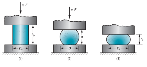
Figure 10: Actual deformation of a cylindrical workpart in open-die forging, showing pronounced barreling: (1) start of process, (2) partial deformation, and (3) final shape.

Where F,  , and A have constant definitions as within the previous equation; and K_(f )is that the formation form issue, outlined as

Where  = coefficient of friction; D = workpart diameter or other dimension representing contact length with die surface, mm (in); and h = workpart height, mm (in).
Impression-Die Forging:
Impression-die forging, typically known as closed-die forging, is performed with dies that contain the inverse of the specified form of the half. The method is illustrated in an exceedingly three-step sequence in figure. The raw work is shown as a cylindrical half the same as that employed in the previous open-die operation. Because the die closes to its final position, flash is made by metal that flows on the far side the die cavity and into the little gap between the die plates. Though this flash should be cut removed from the half in an exceedingly consequent trimming operation, it truly serves a crucial perform throughout impression-die forging. Because the flash begins to create within the die gap, friction resists continuing flow of metal into the gap, so confining the majority of the work material to stay within the die cavity. In hot forging, metal flow is additional restricted as a result of the skinny flash cools quickly against the die plates, thereby increasing its resistance to deformation. Limiting metal flow within the gap causes the compression pressures on the half to extend considerably, so forcing the fabric to fill the typically involved details of the die cavity to confirm a high-quality product.
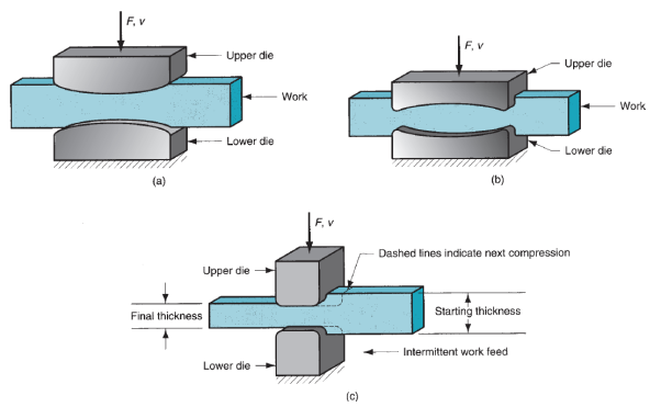
Figure 11: Several open-die forging operations: (a) fullering, (b) edging, and (c) cogging.
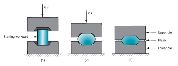
Figure 12: Sequence in impression-die forging: (1) just prior to initial contact with raw workpiece, (2) partial compression, and (3) final die closure, causing flash to form in gap between die plates.
Many forming steps are usually needed in impression-die forging to rework the beginning blank into the specified final pure mathematics. Separate cavities within the die are required for every step. The start steps are designed to spread the metal within the work half to attain an identical deformation and desired metallurgic structure in the consequent steps. The ultimate steps bring the half to its final pure mathematics. Additionally, once drop forging is employed, many blows of the hammer is also needed for every step. Once impression-die drop forging is completed manually, because it usually is, sizable operator ability is needed below adverse conditions to attain consistent results. Attributable to flash forging in impression die forging and therefore the a lot of complicated half shapes created with these dies, forces during this method are considerably larger and harder to research than in open-die forging.
Comparatively easy formulas and style factors are usually accustomed estimate forces in impression-die forging. The force formula is that the same as previous equivalent. For open-die forging, however its interpretation is slightly different:

Where F = most force within the operation, N(lb); A = projected space of the half together with flash, mm2 (in2); Y_f = flow stress of the fabric, MPa (lb/in2); and K_f = formation form issue. In hot forging, the suitable worth of Y_f is the yield strength of the metal at the elevated temperature. In different cases, choosing the right worth of flow stress is troublesome as a result of the strain varies throughout the work for complicated shapes. K_f in eq. Could be a issue supposed to account for will increase effective needed to forge half shapes of assorted complexities. Obviously, the matter of specifying the right K_f worth for a given workpart limits the accuracy of the force estimate. On top of equation applies to the utmost force throughout the operation, since this can be the load which will confirm the specified capability of the press or hammer employed in the operation.
The utmost force is reached at the tip of the forging stroke, once the projected space is greatest and friction is most. Impression-die forging isn't capable of shut tolerance work, and machining is usually needed to attain the accuracies required. The fundamental pure mathematics of the half is obtained from the forging method, with machining performed on those parts of the half that need preciseness finishing (e.g., holes, threads, and surfaces that mate with different components). The benefits of forging, compared to machining the half fully, are higher production rates, conservation of metal, larger strength, and favorable grain orientation of the metal that results from forging. Enhancements within the technology of impression-die forging have resulted in the capability to supply forgings with dilutant sections, a lot of complicated geometries, forceful reductions in draft needs on the dies, nearer tolerances, and therefore the virtual elimination of machining allowances. Forging processes with these options are referred to as preciseness forging. Common work metals used for preciseness forging embody atomic number 13 and metallic element. Note that preciseness formation during this example doesn't eliminate flash, though it reduces it. Some preciseness forging operations are accomplished while not manufacturing flash. Counting on whether or not machining is needed to end the half pure mathematics, preciseness forgings are properly classified as close to internet form or net shape processes.

Figure 13: Comparison of metal grain flow in a part that is: (a) hot forged with finish machining, and (b) machined complete.
Flashless Forging:
As mentioned on top of, impression-die forging is typically known as closed-die forging in business language. However, there's a technical distinction between impression-die forging and true closed-die forging. The excellence is that in closed-die forging, the raw work is totally contained among the die cavity throughout compression, and no flash is made. The term flashless forging is suitable to spot this method. Flashless forging imposes needs on method management that are a lot of hard-to-please than impression-die forging. Most significant is that the work volume should equal the area within the die cavity among awfully shut tolerance. If the beginning blank is just too massive, excessive pressures could cause harm to the die or press. If the blank is just too little, the cavity won't be crammed. Attributable to the special demands created by flashless forging, the method lends itself best to half geometries that are typically easy and symmetrical, and to figure materials love atomic number 13 and Mg and their alloys. Flashless forging is usually classified as a preciseness forging method. Forces in flashless forging reach values resembling those in impression-die forging. Estimates of those forces may be computed mistreatment constant ways as for impression-die forging. Coining could be a special application of closed-die forging during which fine details within the die are affected into the highest and bottom surfaces of the work half. There’s very little flow of metal in coining, nonetheless the pressures needed to breed the surface details within the die cavity are high, as indicated by the worth of Kf. a typical application of coining is, of course, within the minting of coins. The method is additionally accustomed give sensible surface end and dimensional accuracy on work elements created by different operations.
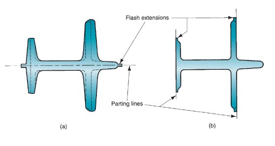
Figure 14: Cross sections of (a) conventional- and (b) precision forgings. Dashed lines in (a) indicate subsequent machining required to make the conventional forging equivalent in geometry to the precision forging. In both cases, flash extensions must be trimmed.
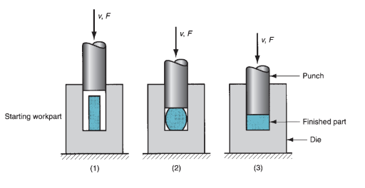
Figure 15: Flashless forging: (1) just before initial contact with workpiece, (2) partial compression, and (3) final punch and die closure. Symbols v and F indicate motion (v = velocity) and applied force, respectively.
2.4.3 Extrusion:
Extrusion could be a compression method during which the work metal is forced to flow through a die gap to supply a desired cross-sectional form. The method may be likened to compressing dentifrice out of a toothpaste tube. Extrusion dates from around 1800. There are many blessings of the trendy process: (1) a spread of shapes are attainable, particularly with hot extrusion; (2) grain structure and strength properties are increased in cold and heat extrusion; (3) fairly shut tolerances are attainable, particularly in cold extrusion; and (4) in some extrusion operations, very little or no wasted material is formed. However, a limitation is that the cross section of the extruded half should be uniform throughout its length.
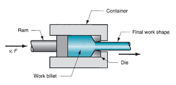
Figure 16: Extrusion.
Analysis of Extrusion:
Allow us to use below figure as a reference in discussing a number of the parameters in extrusion. The diagram assumes that each billet and extrudate is spherical in cross section. One vital parameter is that the extrusion quantitative relation, conjointly known as the reduction quantitative relation. The quantitative relation is defined:

Where  = extrusion ratio;
  = cross-sectional area of the starting billet,mm2 (in2); and
  = final cross-sectional area of the extruded section, mm2 (in2). The quantitative relation applies for each direct and indirect extrusion. The worth of rx may be accustomed confirm true strain in extrusion, on condition that ideal deformation happens with no friction and no redundant work:

Under the belief of ideal deformation (no friction and no redundant work), the pressure applied by the ram to compress the billet through the die gap pictured in our figure may be computed as follows:

Where = average flow stress during deformation, MPa (lb/in2).

In reality, extrusion isn't a resistance method, and therefore the previous equations grossly underestimate the strain pressure in an extrusion operation. Friction exists between the die and therefore the work because the billet squeezes down and passes through the die gap. In direct extrusion, friction conjointly exists between the instrumentation wall and therefore the billet surface. The impact of friction is to extend the strain fully fledged by the metal. Thus, the particular pressure is larger than that, which assumes no friction.
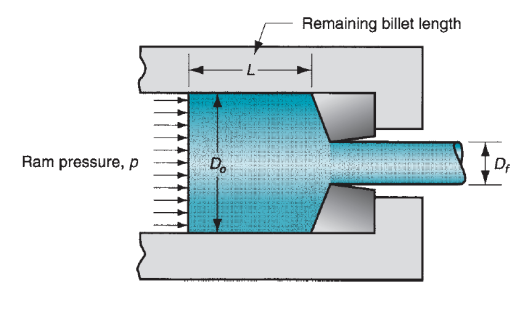
Figure 17: Pressure and other variables in direct extrusion.
Varied ways are recommended to calculate the particular true strain and associated ram pressure in extrusion. The subsequent empirical equation projected by Johnson for estimating extrusion strain has gained sizable recognition:

Where  = extrusion strain; and a and b are empirical constants for a given die angle. Typical values of these constants are: a = 0.8 and b = 1.2 to 1.5. Values of a and b tend to increase with increasing die angle.
The ram pressure to perform indirect extrusion may be calculable supported Johnson’s extrusion strain formula as follows:

Where  is calculated based on ideal strain, rather than extrusion strain.
In direct extrusion, the impact of friction between the instrumentation walls and therefore the billet causes the ram pressure to be larger than for indirect extrusion. We are able to write the subsequent expression that isolates the friction force within the direct extrusion container:

Where  = additional pressure required to overcome friction, MPa (lb/in2);
  = billet cross-sectional area, mm2 (in2);
  = coefficient of friction at the container wall;
  = pressure of the billet against the container wall, MPa (lb/in2); and
  = area of the interface between billet and container wall,mm2 (in2).The right-hand aspect of this equation indicates the billet-container friction force, and therefore the left-hand aspect offers the extra ram force to beat that friction. Within the worst case, protrusive happens at the instrumentation wall in order that friction stress equals shear yield strength of the work metal:

Where  = shear yield strength, MPa (lb/in2). If we assume that
  =
=  /2, then
  reduces to the following:

Based on this reasoning, the subsequent formula may be accustomed figure ram pressure in direct extrusion:

Where the term  accounts for the extra pressure because of friction at the instrumentation - billet interface. L is that the portion of the billet length remaining to be extruded, and Do is that the original diameter of the billet. Note that p is reduced because the remaining billet length decreases throughout the method. Typical plots of ram pressure as a perform of ram stroke for direct and indirect extrusion are given in figure. With sensible lubrication, ram pressures would be less than values calculated by this equation.
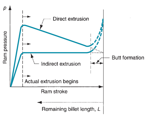
Figure 18: Typical plots of ram pressure versus ram stroke (and remaining billet length) for direct and indirect extrusion. The higher values in direct extrusion result from friction at the container wall. The shape of the initial pressure buildup at the beginning of the plot depends on die angle (higher die angles cause steeper pressure buildups). The pressure increase at the end of the stroke is related to formation of the butt.
Ram force in indirect or direct extrusion is just pressure p increased by billet space Ao:

Where F = ram force in extrusion, N (lb). Power needed to hold out the extrusion operation is just

Where P = power, J/s (in-lb/min); F = ram force, N (lb); and v = ram velocity, m/s (in/min).
2.4.4 Wire and Bar Drawing:
Within the context of bulk deformation, drawing is Associate in Nursing operation during which the cross section of a bar, rod, or wire is reduced by pull it through a die gap. The overall options of the method are the same as those of extrusion. The distinction is that the work is force through the die in drawing, whereas it's pushed through the die in extrusion. Though the presence of tensile stresses is apparent in drawing, compression conjointly plays a big role as a result of the metal is squeezed down because it passes through the die gap. For this reason, the deformation that happens in drawing is typically said as indirect compression. Drawing could be a term conjointly employed in sheet shaping. The term wire and bar drawing is employed to differentiate the drawing method mentioned here from the sheet process of constant name.
In an exceedingly drawing operation, the amendment in size of the work is typically given by the realm reduction, outlined as follows:
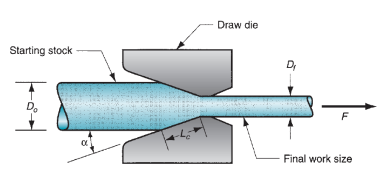
Figure 19: Drawing of bar, rod, or wire.

Where r = area reduction in drawing;  = original area of work,mm2 (in2); and
  = final area, mm2 (in2). Space reduction is usually expressed as a share.
In bar drawing, rod drawing, and in drawing of enormous diameter wire for disconcerting and heading operations, the term draft is employed to denote the before and once distinction in size of the processed work. The draft is just the distinction between original and final stock diameters:

Where d = draft, mm (in); Do = original diameter of work, mm (in); and Df = final work diameter, mm (in).
Analysis of Drawing:
During this section, we have a tendency to take into account the mechanics of wire and bar drawing. However are stresses and forces computed within the process? We have a tendency to conjointly take into account how massive a discount is feasible in an exceedingly drawing operation.
Mechanics of Drawing:
If no friction or redundant work occurred in drawing, true strain may well be determined as follows:

Where  and
and  are the original and final cross-sectional areas of the work, as previously defined; and r = drawing reduction. The stress that results from this ideal deformation is given by

Where  = average flow stress based on the value of strain.
As a result of friction is gift in drawing and therefore the work metal experiences heterogeneous deformation, the particular stress is larger than provided by on top of equivalent. Additionally to the quantitative relation Ao/Af, different variables that influence draw stress are die angle and constant of friction at the work–die interface. Varieties of ways are projected for predicting draw stress supported values of those parameters.

Where  = draw stress, MPa (lb/in2);
  = die-work coefficient of friction;
  = die angle (half-angle); and φ could be an issue that accounts for heterogeneous deformation that is decided as follows for a spherical cross section:

Where D = average diameter of labor throughout drawing, mm (in); and animal product = contact length of the work with the draw die, mm(in). Values of D and Lc may be determined from the following:


The corresponding draw force is then the realm of the drawn cross section increased by the draw stress:

Where F = draw force, N (lb); and therefore the different terms are outlined on top of. The facility needed in an exceedingly drawing operation is that the draw force increased by exit speed of the work.
Maximum Reduction per Pass:
A matter which will occur to the reader is: Why is over one step needed to attain the specified reduction in wire drawing? Why not take the whole reduction in an exceedingly single go through one die, as in extrusion? The solution may be explained as follows. From the preceding equations, it's clear that because the reduction will increase draw stress increases. If the reduction is massive enough, draw stress can exceed the yield strength of the exiting metal.
Once that happens the drawn wire can merely elongate rather than new material being squeezed through the die gap. For wire drawing to achieve success, most draw stress should be lower than the yield strength of the exiting metal. It’s an uncomplicated pertain confirm this most draw stress and therefore the ensuing maximum attainable reduction that may be created in one pass, below bound assumptions. Allow us to assume a superbly plastic metal (n = 0), no friction, and no redundant work. During this ideal case, the utmost attainable draw stress is capable the yield strength of the work material. Expressing this mistreatment the equation for draw stress below conditions of ideal deformation, and setting  = Y (because n = 0),

This implies that  =
= . That is,
  max = 1.0. In order for
  max to be zero, then
  =
= must equal the natural logarithm base e. Consequently, the utmost attainable space quantitative relation is

And the utmost attainable reduction is

The worth given by on top of equivalent. Is usually used because the theoretical most reduction attainable in an exceedingly single draw, even if it ignores (1) the results of friction and redundant work, which might scale back the utmost attainable worth, and (2) strain hardening, which might increase the utmost attainable reduction as a result of the exiting wire would be stronger than the beginning metal. In observe draw reductions per pass are quite below the theoretical limit. Reductions of 0.50 for single-draft bar drawing and 0.30 for multiple-draft wire drawing appear to be the higher limits in industrial operations.
Sheet shaping includes cutting and forming operations performed on comparatively skinny sheets of metal. Typical sheet-metal thicknesses are between 0.4 millimeter (1/64 in) and six mm (1/4 in).When thickness exceeds concerning six millimeter, the stock is typically said as plate instead of sheet. The sheet or plate stock employed in sheet shaping is made by flat rolling. The foremost normally used sheet is low steel (0.06% – 0.15% C typical). Its low value and sensible formability, combined with sufficient strength for many product applications, build it ideal as a beginning material.
2.5.1 Cutting Operations:
Cutting of sheet is accomplished by a cut action between 2 sharp cutting edges. The cut action is pictured within the four stop-action sketches of below figure, during which the higher leading edge (the punch) sweeps down past a stationary lower cutting edge (the die). Because the punch begins to push into the work, plastic deformation happens within the surfaces of the sheet. Because the punch moves downward, penetration happens during which the punch compresses the sheet and cuts into the metal. This penetration zone is mostly concerning simple fraction the thickness of the sheet. Because the punch continues to travel into the work, fracture is initiated within the work the 2 cutting edges.If the clearance between the punch and die is correct, the 2 fracture lines meet, leading to a clean separation of the work into 2 items.

Figure 20: Shearing action
Shearing, Blanking, and Punching:
The 3 most significant operations in pressworking that cut metal by the cut mechanism simply represented are shearing, blanking, and punching. Cut could be a sheet-metal cutting operation on a line between 2 cutting edges, as shown in Figure (a). Cut is often accustomed cut massive sheets into smaller sections for consequent pressworking operations. It’s performed on a machine known as an influence shears, or squaring shears. The higher blade of the facility shears is usually inclined, as shown in Figure (b), to scale back the specified cutting force.
Blanking involves cutting of the sheet on a closed define in an exceedingly single step to separate the piece from the encompassing stock, as in Figure (a). The half that's cut out is that the desired product within the operation and is termed the blank. Punching is analogous to blanking except that it produces a hole, and therefore the separated piece is scrap, known as the slug. The remaining stock is that the desired half. The excellence is illustrated in Figure (b).
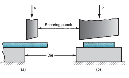
Figure 21: Shearing operation: (a) side view of the shearing operation; (b) front view of power shears equipped with inclined upper cutting blade. Symbol v indicates motion.
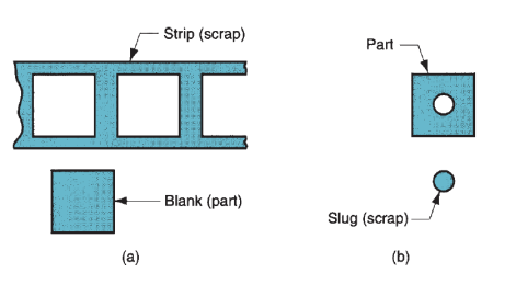
Figure 22: (a) Blanking and (b) punching.
Engineering Analysis of Sheet-Metal Cutting:
Method parameters in sheet-metal cutting are clearance between punch and die, stock thickness, sort of metal and its strength, and length of the cut. Allow us to outline these parameters and a few of the relationships among them.
Clearance:
The clearance c in an exceedingly cut operation is that the distance between the punch and die. Typical clearances in typical pressworking vary between 4% and 8% of the sheet-metal thickness t. The impact of improper clearances is illustrated in figure. If the clearance is just too little, then the fracture lines tend to pass one another, inflicting a double burnishing and bigger cutting forces. If the clearance is just too massive, the metal becomes pinched between the cutting edges and an excessive burr results. In special operations requiring terribly straight edges, love shaving and fine blanking, clearance is barely concerning 1% of stock thickness. The proper clearance depends on sheet-metal sort and thickness. The counseled clearance may be calculated by the subsequent formula:

Where c = clearance, mm(in); Ac = clearance allowance; and t = stock thickness, mm (in). The clearance allowance is decided consistent with sort of metal.
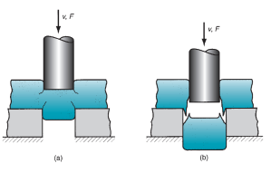
Figure 23: Effect of clearance: (a) clearance too small causes less-than optimal fracture and excessive forces; and (b) clearance too large causes oversized burr. Symbols v and F indicate motion and applied force, respectively.
The die gap should be larger than the punch size (obviously). Whether or not to feature the clearance worth to the die size or compute it from the punch size depends on whether the half being cut out could be a blank or a slug, as illustrated in figure for a circular half. Attributable to the pure mathematics of the sheared edge, the outer dimension of the half cut out of the sheet are larger than the opening size. Thus, punch and die sizes for a spherical blank of diameter decibel are determined as


Punch and die sizes for a round hole of diameter Dh are determined as:


In order for the slug or blank to drop through the die, the die gap should have an angular clearance of 0.250 to 1.50 on each side.
Cutting Forces:
Estimates of cutting force are vital as a result of this force determines the scale (tonnage) of the press required. Cutting force F in sheet working may be determined by

Where S = shear strength of the sheet metal, MPa (lb/in2); t = stock thickness, mm (in), and L = length of the cut edge, mm (in). In blanking, punching, slotting, and similar operations, L is that the perimeter length of the blank or hole being cut. The minor impact of clearance in determinative the worth of L may be neglected. If shear strength is unknown, another method of estimating the cutting force is to use the tensile strength:

Where TS = ultimate tensile strength MPa (lb/in2).
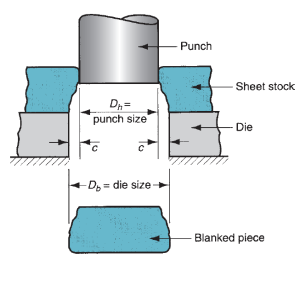
Figure 24: Die size determines blank size Db; punch size determines hole size Dh.; c = clearance.
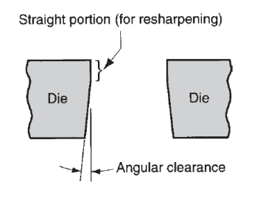
Figure 25: Angular clearance.
These equations for estimating cutting force assume that the whole cut on the sheared edge length L is created at constant time. During this case the cutting force are a most. It’s attainable to scale back the utmost force by mistreatment Associate in nursing angulate leading edge on the punch or die. The angle (called the shear angle), spreads the cut over time and reduces the force fully fledged at anyone moment. However, the entire energy needed within the operation is that the same, whether or not it's focused into a quick moment or distributed over an extended period of time.
2.5.2 Bending Operations:
Bending in sheet-metalwork is outlined because the straining of the metal around a straight axis. Throughout the bending operation, the metal on the within of the neutral plane is compressed, whereas the metal on the skin of the neutral plane is stretched. The metal is plastically unshapely in order that the bend takes a permanent attack removal of the stresses that caused it. Bending produces very little or no amendment within the thickness of the sheet.
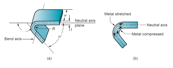
Figure 26: (a) Bending of sheet metal; (b) both compression and tensile elongation of the metal occur in bending.
Engineering Analysis of Bending:
a number of the vital terms in sheet-metal bending are known in figure. The metal of thickness t is bent through an angle called the bend angle . This results in a sheet-metal part with an included angle α', where α + α' = 1800. The bend radius R is generally given on the within of the half, instead of at the neutral axis, and is decided by the radius on the tooling accustomed perform the operation. The bend is created over the dimension of the work w.
Bend Allowance:
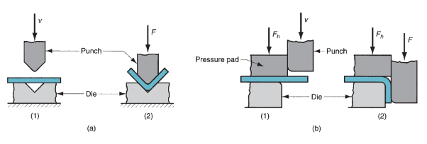
Figure 27: Two common bending methods: (a) V-bending and (b) edge bending; (1) before and (2) after bending. Symbols: v ¼ motion, F ¼ applied bending force, Fh ¼ blank.
If the bend radius is little relative to stock thickness, the metal tends to stretch throughout bending. It's vital to be ready to estimate the number of stretching that happens, if any, in order that the ultimate half-length can match the desired dimension. The matter is to see the length of the neutral axis before bending to account for stretching of the ultimate bent section. This length is termed the bend allowance, and it may be calculable as follows:

Where  = bend allowance, mm (in);
  = bend angle, degrees; R = bend radius, mm (in); t = stock thickness, mm (in); and
 is factor to estimate stretching. The following design values are recommended for
  : if <2t,
  = 0.33; and if R≥2t,
  = 0.50. The values of
  predict that stretching occurs only if bend radius is small relative to sheet thickness.
Springback:
When the bending pressure is removed at the top of the deformation operation, elastic energy remains within the bent half, inflicting it to recover partly toward its original form. This elastic recovery is termed springback, outlined because the increase in enclosed angle of the bent half relative to the included angle of the forming tool when the tool is removed.

Where SB = springback;  = included angle of the sheet-metal part, degrees; and
  = included angle of the bending tool, degrees. . Although not as obvious, a rise within the bend radius additionally happens thanks to elastic recovery. The number of springback will increase with modulus of physical property E and yield strength Y of the work metal.
Bending Force:
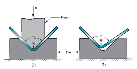
Figure 28: Springback in bending shows itself as a decrease in bend angle and an increase in bend radius: (1) during the operation, the work is forced to take the radius Rt and included angle  = determined by the bending tool (punch in V-bending); (2) after the punch is removed, the work springs back to radius R and included angle
 . Symbol: F = applied bending force.
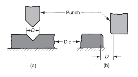
Figure 29: Die opening dimension D: (a) V-die, (b) wiping die.
The force needed to perform bending depends on the pure mathematics of the punch-and-die and the strength, thickness, and length of the sheet. The utmost bending force may be calculable by means that of the subsequent equation:

Where F = bending force, N (lb); TS = tensile strength of the sheet metal, MPa (lb/in2); w = width of part in the direction of the bend axis, mm (in); t = stock thickness, mm (in); and D = die opening dimension, mm (in). This equation is predicated on bending of an easy beam in mechanics, and  that accounts for variations encountered in actual bending method. It’s worth depends on style of bending: for V-bending = 1.33; and for edge bending = 0.33.
2.5.3 Drawing:
Drawing could be sheet-metal-forming operation accustomed make concave, box-shaped, or alternative complex-curved and recessed elements. It is performed by putting a chunk of sheet over a die cavity and so pushing the metal into the gap with a punch. The blank should typically be control down flat against the die by a blankholder. Common elements created by drawing embrace beverage cans, ammunition shells, sinks, preparation pots, and automobile body panels.
Mechanics of Drawing:
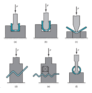
Figure 30: Miscellaneous bending operations: (a) channel bending, (b) U-bending, (c) air bending, (d) offset bending, (e) corrugating, and (f) tube forming. Symbol: F = applied force.
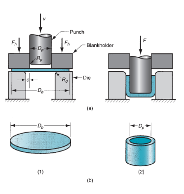
Figure 31: (a) Drawing of a cup shaped part: (1) start of operation before punch contacts work, and (2) near end of stroke; and (b) corresponding workpart: (1) starting blank, and (2) drawn part. Symbols: c ¼ clearance, Db = blank diameter, Dp = punch diameter, Rd = die corner radius, Rp = punch corner radius, F = drawing force, Fh = holding force.
Drawing of a concave half is that the basic drawing operation, with dimensions and parameters as pictured in below figure. A blank of diameter Db is drawn into a die cavity by means that of a punch with diameter Dp. The punch and die should have corner radii, given by Rp and Rd. If the punch and die were to possess sharp corners (Rp and Rd = 0), a hole-punching operation (and not an awfully smart one) would be accomplished rather than a drawing operation. The edges of the punch and die are separated by a clearance c. This clearance in drawing is regarding 10% larger than the stock thickness:

The punch applies a downward force F to accomplish the deformation of the metal, and a downward holding force Fh is applied by the blankholder, as shown within the sketch.As the punch takings downward toward its final bottom position, the work experiences a complex sequence of stresses and strains because it is bit by bit fashioned into the form defined by the punch and die cavity. Because the punch 1st begins to push into the work, the metal is subjected to a bending operation. The sheet is just bent over the corner of the punch and therefore the corner of the die. The surface perimeter of the blank moves in toward the middle during this 1st stage, however solely slightly.
As the punch moves additional down, a straightening action happens within the metal that was previously bent over the die radius. The metal at rock bottom of the cup, likewise as on the punch radius, has been moved downward with the punch; however the metal that was bent over the die radius must currently be straightened so as to be force into the clearance to make the wall of the cylinder. At a similar time, additional metal should be superimposed to switch that being employed within the cylinder wall. This new metal comes from the surface edge of the blank. The metal within the outer parts of the blank is force or drawn toward the die gap to resupply the antecedently bent and straightened metal now forming the cylinder wall. This sort of metal flow through a constricted space offers the drawing method its name.
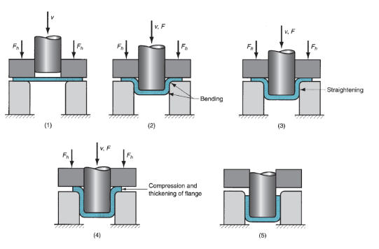
Figure 32: Stages in deformation of the work in deep drawing: (1) punch makes initial contact with work, (2) bending, (3) straightening, (4) friction and compression, and (5) final cup shape showing effects of thinning in the cup walls. Symbols: v = motion of punch, F = punch force, Fh = blank holder force.
Engineering Analysis of Drawing:
It is very important to assess the restrictions on the amount of drawing that may be accomplished. This can be often target-hunting by easy measures that may be without delay calculated for a given operation. Additionally, drawing force and holding force are necessary method variables. Finally, the starting blank size should be determined.
Measures of Drawing:
One of the measures of the severity of a deep drawing operation is that the drawing quantitative relation DR. This can be most simply outlined for a cylindrical form because the ratio of blank diameter Db to punch diameter Dp. In equation type,

The drawing quantitative relation provides a sign, albeit a crude one, of the severity of a given drawing operation. The larger the quantitative relation, the additional severe is that the operation. An approximate higher limit on the drawing quantitative relation could be a worth of two. The actual limiting worth for a given operation depends on punch and die corner radii (Rp and Rd), friction conditions, depth of draw, and characteristics of the sheet (e.g., ductility, degree of radial asymmetry of strength properties within the metal).
Another way to characterize a given drawing operation is by the reduction r, where

It is very closely regarding drawing quantitative relation. In step with the previous limit on DR (DR < 2.0), the value of reduction r should be less than 0.50.
A third live in deep drawing is that the thickness-to-diameter quantitative relation t/Db (thickness of the beginning blank t divided by the blank diameter Db). Often expressed as a share, it's fascinating for the t/Db quantitative relation to be larger than 1%. As t/Db decreases, tendency for wrinkling increases.
In cases wherever these limits on drawing quantitative relation, reduction, and t/Db quantitative relation are exceeded by the look of the drawn half, the blank should be drawn in 2 or more steps, generally with hardening between the steps.
Powder science (PM) could be a metal process technology during which elements are created from aluminiferous powders. Within the usual PM production sequence, the powders are compressed into the required form and so heated to cause bonding of the particles into a tough, rigid mass. Compression, called pressing, is accomplished during a press-type machine victimization tools designed specifically for the half to be factory-made. The tooling, which generally consists of a die and one or additional punches, may be expensive, and PM is thus most applicable for medium and high production. The heating treatment, called sintering, is performed at a temperature below the melting point of the metal.
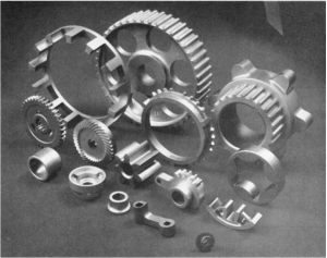
Figure 33: A collection of powder metallurgy parts. (Courtesy of Dorst America, Inc.)
Conventional Pressing and Sintering:
The typical PM sequence consists of 3 steps: (1) mixing and admixture of the powders; (2) compaction, during which the powders are ironed into the required half shape; and (3) sintering, that involves heating to a temperature below the freezing point to cause solid-state bonding of the particles and strengthening of the part. The 3 steps generally referred to as primary operations in PM. Additionally, secondary operations are sometimes performed to boost dimensional accuracy, increase density, and for other reasons.
Blending and Mixing of the Powders:
To win triple-crown leads to compaction and sintering, the aluminiferous powders should be completely homogenized beforehand. The terms mixing and admixture are each employed in this context. Mixing refers to when powders of a similar chemical composition however probably totally different particle sizes are amalgamated. Totally different particle sizes are usually emulsified to scale back body. Mixing refers to powders of various chemistries being combined. A bonus of PM technology is that the chance to combine numerous metals into alloys that will be tough or not possible to supply by alternative means that. The excellence between blending and admixture isn't perpetually precise in industrial apply.
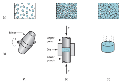
Figure 34: The conventional powder metallurgy production sequence: (1) blending, (2) compacting, and (3) sintering; (a) shows the condition of the particles, whereas (b) shows the operation and/ or workpart during the sequence.
Blending and mixing are accomplished by mechanical means that. Four alternatives are illustrated in figure: (a) rotation during a drum; (b) rotation in a double-cone container; (c) agitation during a screw mixer; and (d) stirring in a blade mixer. There is additional science to those devices than one would suspect. Best results seem to occur once the instrumentation is between 20% and 40% full. The containers are typically designed with internal baffles or alternative ways that of preventing free-fall throughout mixing of powders of various sizes, as a result of variations in settling rates between sizes lead to segregation - simply the other of what's wanted in mixing. Vibration of the powder is undesirable, as a result of it additionally causes segregation.
Alternative ingredients are typically superimposed to the aluminiferous powders throughout the mixing and/ or mixing step. These additives embrace (1) lubricants, comparable to stearates of Zn and Al, in tiny amounts to scale back friction between particles and at the die wall throughout compaction; (2) binders, that are needed in some cases to achieve adequate strength within the ironed however international organization work parts; and (3) deflocculants, that inhibit agglomeration of powders for higher flow characteristics throughout resulting process.
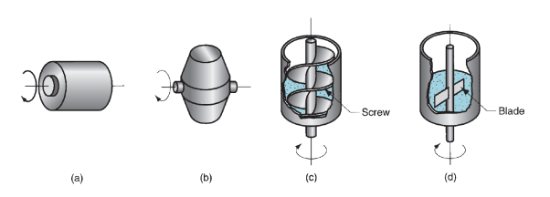
Figure 35: Several blending and mixing devices: (a) rotating drum, (b) rotating double-cone, (c) screw mixer, and (d) blade mixer.
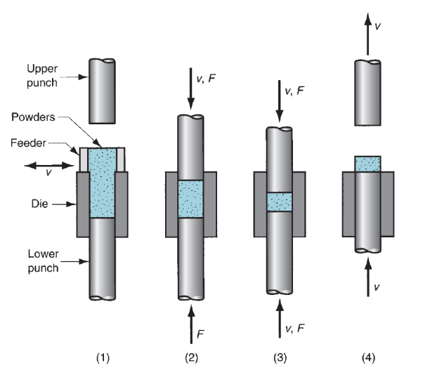
Figure 36: Pressing, the conventional method of compacting metal powders in PM: (1) filling the die cavity with powder, done by automatic feed in production, (2) initial, and (3) final positions of upper and lower punches during compaction, and (4) ejection of part.
Compaction:
In compaction, high is applied to the powders to make them into the required form. The standard compaction technique is pressing, in which opposing punches squeeze the powders contained during a die. The steps within the pressing cycle are shown in figure. The workpart when pressing is termed a green compact, the word inexperienced which means not nevertheless absolutely processed. As a result of pressing, the density of the half, known as the inexperienced density, is far larger than the beginning bulk density. The inexperienced strength of the half once ironed is adequate for handling however way below that achieved when sintering. The applied pressure in compaction results at first in repacking of the powders into an additional economical arrangement, eliminating ‘‘bridges’’ fashioned throughout filling, reducing pore house, and increasing the quantity of contacting points between particles. As pressure will increase, the particles are plastically deformed, inflicting lay particle contact space to extend and extra particles to create contact. This can be amid an additional reduction in pore volume. The progression is illustrated in 3 views in below figure for starting particles of spherical form. Additionally shown is that the associated density represented by the 3 views as operate of applied pressure.
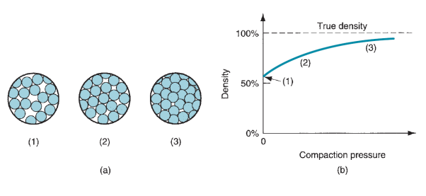
Figure 37: (a) Effect of applied pressure during compaction: (1) initial loose powders after filling, (2) repacking, and (3) deformation of particles; and (b) density of the powders as a function of pressure.
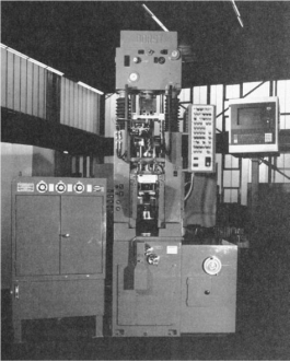
Figure 38: A 450-kN (50-ton) hydraulic press for compaction of powder metallurgy components. (Photo courtesy of Dorst America, Inc.)
Presses used in typical PM compaction are mechanical, hydraulic, or a mixture of the two. A 450 kN (50 ton) hydraulic unit is shown in figure. Because of differences partly complexness and associated pressing necessities, presses can be distinguished as (1) pressing from one direction, observed as single-action presses; or (2) pressing from 2 directions, any of many types together with opposed ram, double-action, and multiple action. Current available press technology will offer up to ten separate action controls to produce elements of great geometric complexness.
The capacity of a press for PM production is mostly given in tons or kN or MN. The required force for pressing depends on the projected space of the PM half (area in the horizontal plane for a vertical press) increased by the pressure required to compact the given metal powders. Reducing this to equation form

Where F = required force, N (lb);  = projected area of the part, mm2 (in2); and
  = compaction pressure required for the given powder material, MPa (lb/in2).
Compaction pressures usually vary from seventy MPa (10,000 lb/in2) for Al powders to 700 MPa (100,000 lb/in2) for iron and steel powders.
Sintering:
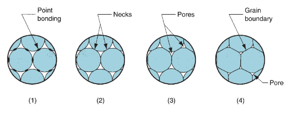
Figure 39: Sintering on a microscopic scale: (1) particle bonding is initiated at contact points; (2) contact points grow into ‘‘necks’’; (3) the pores between particles are reduced in size; and (4) grain boundaries develop between particles in place of the necked regions.
When pressing, the inexperienced compact lacks strength and hardness; it's simply fragmented under low stresses. Sintering could be a heat treatment operation performed on the compact to bond its aluminiferous particles, thereby increasing strength and hardness. The treatment is typically administered at temperatures between zero.7 and 0.9 of the metal’s freezing point (absolute scale). The terms solid-state sintering or solid-phase sintering are generally used for this typical sintering because the metal remains un-melted at these treatment temperatures.
It is generally united among researchers that the first thrust for sintering is reduction of surface energy. The inexperienced compact consists of the many distinct particles; every with its own individual surface, and then the whole surface area contained within the compact is extremely high. Underneath the influence of heat, the expanse is reduced through the formation and growth of bonds between the particles, with associated reduction in surface energy. The finer the initial powder size, the upper the whole expanse, and therefore the larger the driving force behind the method.
The series of sketches in figure shows on a microscopic scale the changes that occur during sintering of aluminiferous powders. Sintering involves mass transport to create the necks and remodel them into grain boundaries. The principal mechanism by that this happens is diffusion; alternative potential mechanisms embrace plastic flow. Shrinkage happens throughout sintering as a results of pore size reduction. This relies to an oversized extent on the density of the inexperienced compact, which depends on the pressure throughout compaction. Shrinkage is mostly predictable once process conditions are closely controlled. As a result of PM applications typically involves medium-to-high production, most sintering furnaces are designed with mechanized flow-through capability for the workparts. The heat treatment consists of 3 steps, accomplished in 3 chambers in these continuous furnaces: (1) heat, during which lubricants and binders are burned off; (2) sinter; and (3) settle down. In modern sintering apply, the atmosphere within the chamber is controlled. The purposes of a controlled atmosphere embrace (1) protection from oxidization, (2) providing a reducing atmosphere to get rid of existing oxides, (3) providing a carburizing atmosphere, and (4) helping in removing lubricants and binders used in pressing. Common sintering chamber atmospheres are element, nitrogen-based, unconnected ammonia, hydrogen, and gas. Vacuum atmospheres are used sure metals, comparable to chrome steel and metal.
Machining isn't only 1 process; it's a gaggle of processes. The common feature is that the use of a cutting tool to create a chip that's off from the workpart. To perform the operation, relative motion is needed between the tool and work. This relative motion is achieved in most machining operations by means that of a primary motion, referred to as the cutting speed, and a secondary motion, referred to as the feed. The form of the tool and its penetration into the surface, combined with these motions, produces the required geometry of the ensuing surface.
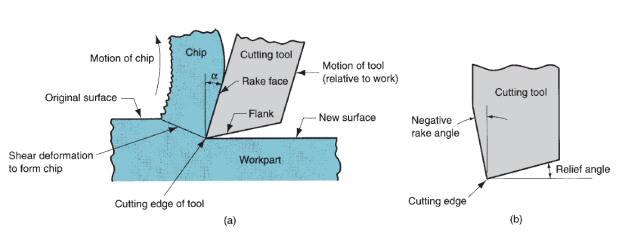
Figure 40: (a) A cross-sectional view of the machining process. (b) Tool with negative rake angle; compare with positive rake angle in (a).
Kinds of Machining Operations:
There are several kinds of machining operations, every of that is capable of generating a part geometry and surface texture. Except for currently it's acceptable to spot and outline the 3 commonest types: turning, drilling, and milling, illustrated in below figure. In turning, a cutting tool with one cutting edge is employed to get rid of material from a rotating workpiece to come up with a cylindrical form. The speed motion in turning is provided by the rotating workpart, and also the feed motion is achieved by the cutting tool moving slowly during a direction parallel to the axis of rotation of the workpiece. Drilling is employed to form a spherical hole. It’s accomplished by a rotating tool that usually has 2 cutting edges. The tool is fed during a direction parallel to its axis of rotation into the workpart to create the spherical hole. In milling, a rotating tool with multiple cutting edges is fed slowly across the work material to come up with a plane or straight surface. The direction of the feed motion is perpendicular to the tool’s axis of rotation. The speed motion is provided by the rotating edge cutter. The 2 basic kinds of edge are peripheral edge and face milling. Alternative standard machining operations embody shaping, planning, broaching, and sawing. Also, grinding and similar abrasive operations are typically enclosed at intervals the class of machining. These processes normally follow the traditional machining operations and are accustomed accomplish a superior surface finish on the workpart.
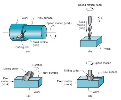
Figure 41: The three most common types of machining processes: (a) turning, (b) drilling, and two forms of milling: (c) peripheral milling, and (d) face milling.
The Cutting tool:
A cutting tool has one or additional sharp cutting edges and is created of a fabric that's more durable than the work material. The cutting edge serves to separate a chip from the parent work material. Connected to the cutting edge are 2 surfaces of the tool: the rake face and also the flank. The rake face, that directs the flow of the fresh fashioned chip, is directed at an exact angle referred to as the rake angle α. It's measured relative to a plane perpendicular to the surface. The rake angle may be positive. The flank of the tool provides a clearance between the tool and also the fresh generated work surface, therefore protective the surface from abrasion, which would degrade the end. This flank surface is directed at angle referred to as the relief angle.
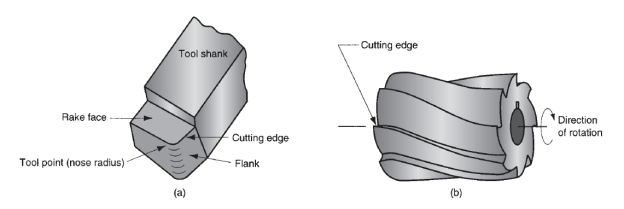
Figure 42: (a) A single-point tool showing rake face, flank, and tool point; and(b)a helical milling cutter, representative of tools with multiple cutting edges.
Single and multi-point cutting:
Most cutting tools in practice have more complicated geometries than those in figure. There are 2 basic sorts,
(a) single-point tools and
(b) multiple-cutting-edge tools.
A single-point tool has one cutting edge and is employed for operations admire turning. There's one tool purpose from that the name of this cutting tool comes. Throughout machining, the purpose of the tool penetrates below the first surface of the part. The purpose is sometimes rounded to an exact radius, referred to as the nose radius.
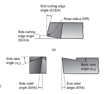
Figure 43: Single Pont cutting tool geometry
Multiple-cutting-edge tools have over one cutting edge and typically accomplish their motion relative to the workpart by rotating. Drilling and edge use rotating multiple-cutting-edge tools. Figure (b) shows a coiling edge cutter utilized in peripheral milling. Although the form is kind of totally different from a single point tool, several components of tool geometry are similar.

Figure 44: Multiple cutting edge tool geometry
By definition, orthogonal cutting uses a wedge-shaped tool during which the cutting edge is perpendicular to the direction of cutting speed. Because the tool is forced into the fabric, the chip is created by shear deformation on a plane referred to as the shear plane that is directed at angle Ø with the surface of the work. Solely at the sharp cutting edge of the tool will failure of the fabric occur, leading to separation of the chip from the parent material.
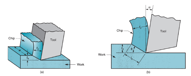
Figure 45: Orthogonal cutting: (a) as a three-dimensional process, and (b) how it reduces to two dimensions in the side view.
On the shear plane, wherever the majority of the energy is consumed in machining, the fabric is plastically distorted. The tool in orthogonal cutting has solely 2 components of geometry: (1) rake angle and (2) clearance angle. As indicated antecedently, the rake angle α determines the direction that the chip flows because it is created from the workpart; and also the clearance angle provides a little clearance between the tool flank and the fresh generated surface. Throughout cutting, the cutting edge of the tool is positioned an exact distance below the first surface. This corresponds to the thickness of the chip before chip formation, to. Because the chip is created on the shear plane, its thickness will increase to tc. The magnitude relation of to to tc is named the chip thickness ratio (or merely the chip ratio) r:

Since the chip thickness once cutting is usually larger than the corresponding thickness before cutting, the chip magnitude relation can forever be not up to one. Additionally to to, the orthogonal cut incorporates a breadth dimension w, even supposing this dimension doesn't contribute abundant to the analysis in orthogonal cutting. The geometry of the orthogonal cutting model permits us to determine a very important relationship between the chip thickness magnitude relation, the rake angle, and also the shear angle. Let ls be the length of the shear plane. We can build the substitutions:
to = ls sin , and tc = lscos(
 ). Thus,

This will be rearranged to work out  as follows:

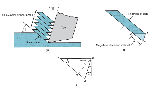
Figure 46: Shear strain during chip formation: (a) chip formation depicted as a series of parallel plates sliding relative to each other; (b) one of the plates isolated to illustrate the definition of shear strain based on this parallel plate model; and (c) shear strain triangle
The shear strain that happens on the shear plane may be calculable by examining below figure. (a) Shows shear deformation approximated by a series of parallel plates slippery against each other to create the chip. As per our definition of shear strain every plate experiences the shear strain shown in figure (b). Relating part (c), this will be expressed as

This may be reduced to the subsequent definition of shear strain in metal cutting as:

Take into account the forces engaged on the chip throughout orthogonal cutting. The forces applied against the chip by the tool may be separated into 2 reciprocally perpendicular components: friction force and traditional force to friction. The friction force F is that the resistance force resisting the flow of the chip along the rake faces of the tool. The normal force to friction N is perpendicular to the friction force. These 2 elements may be accustomed outline the constant of friction between the tool and also the chip:
μ = F/N
The friction force and its traditional force can be additional vectorially to create a resultant force R, that is directed at angle , referred to as the friction angle. Thefriction angle is said to the constant of friction as
μ = tan β
Additionally to the tool forces engaged on the chip, there are two force components applied by the piece of work on the chip: shear force and traditional force to shear. The shear force Fs is that the force that causes shear deformation to occur within the shear plane, and also the traditional force to shear Fn is perpendicular to the shear force. Based on the shear force, we can outline the shear stress that acts on the shear plane between the work and also the chip
τ = Fs /As
Wherever As = space of the shear plane. This shear plane space may be calculated as
As = tow/sin
The shear stress represents the extent of stress needed to perform the machining operation. Therefore, this stress is capable the shear strength of the work material ( = S) beneath the conditions at that cutting happens. Vector addition of the 2 force elements Fs and Fn yields the resultant force R’. So as for the forces engaged on the chip to be in balance, this resultant R’ should be equal in magnitude, opposite in direction, and linear with the resultant R.
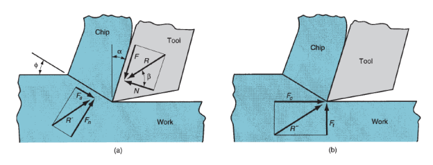
Figure 47: Forces in metal cutting: (a) forces acting on the chip in orthogonal cutting, and (b) forces acting on the tool that can be measured.
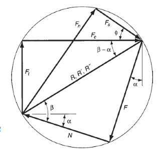
Figure 48: Force diagram showing geometric relationships between F, N, Fs, Fn, Fc, and Ft.
None of the four force elements F, N, Fs, and Fn may be directly measured during a machining operation, as a result of the directions during which they're applied vary with totally different tool geometries and cutting conditions. However, it's doable for the cutting tool to be instrumented employing a force measuring system referred to as a measuring device, so 2 further force elements acting against the tool may be directly measured: cutting force and thrust force. The cutting force Fc is within the direction of cutting, an equivalent direction because the cutting speed v, and also the thrust force Ft is perpendicular to the cutting force and is related to the chip thickness before the move. Beside their resultant force R”. The several directions of those forces are illustrious; therefore the force transducers within the measuring device may be aligned consequently. Equations may be derived to relate the four force elements that can't be measured to the 2 forces which will be measured. Victimization the force diagram in figure, the subsequent geometry relationships may be derived:
F = Fc sin α + Ft cos α
N = Fc cos α – Ft sin α
Fs = Fc cos - Ft sin
Fn = Fc sin + Ft cos
If cutting force and thrust force are illustrious, these four equations may be accustomed calculate estimates of shear force, friction force, and traditional force to friction. Supported these force estimates, shear stress and constant of friction may be determined. Note that within the special case of orthogonal cutting when the rake angle = 0, and scale back to F = Ft and N = Fc, severally. Thus, during this special case, friction force and its traditional force might be directly measured by the measuring device.
The Merchant Equation:
One amongst the necessary relationships in metal cutting was derived by Eugene Merchant. Its derivation was supported the belief of orthogonal cutting, however its general validity extends to three-dimensional machining operations. Merchant started with the definition of shear stress expressed within the type of the subsequent relationship derived:

Merchant reasoned that, out of all the doable angles emanating from the cutting edge of the tool at that shear deformation might occur, there's one angle  that predominates. This is often the angle at that shear stress is simply capable the shear strength of the work material, then shear deformation happens at this angle. For all alternative doable shear angles, the shear stress is a smaller amount than the shear strength; therefore chip formation cannot occur at these alternative angles. In effect, the work material can choose a shear angle that minimizes energy. This angle may be determined by taking the by-product of the shear stress S with reference to
  and setting the by-product to zero. Resolution for
  , we have a tendency to get the link named once Merchant:
= 45 + α/2 – β/2
Among the assumptions within the Merchant equation is that shear strength of the work material could be a constant, unaffected by strain rate, temperature, and alternative factors. As a result of this assumption is profaned in sensible machining operations, the equation should be thought-about an approximate relationship instead of an correct mathematical equation.
We must always note that there are variations between the orthogonal models an actual machining method. First, the shear deformation method doesn't occur on a plane, however at intervals a zone. If cut were to require place across a plane of zero thickness, it might imply that the cut action should occur in a flash because it passes through the plane, instead of over some finite (although brief) period. For the fabric to behave during a realistic manner, the shear deformation must occur at intervals a skinny shear zone. Metal-cutting experiments have indicated that the thickness of the shear zone is merely a few thousandths of an in.
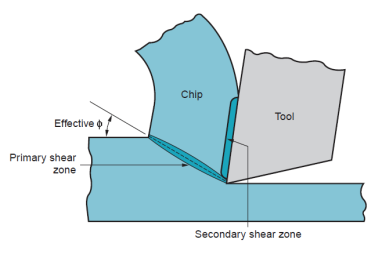
Figure 49: More realistic view of chip formation, showing shear zone rather than shear plane. Also shown is the secondary shear zone resulting from tool–chip friction.

Figure 50: Four types of chip formation in metal cutting: (a) discontinuous, (b) continuous, (c) continuous with built-up edge, (d) serrated.
Since the shear zone is therefore skinny, there's not an excellent loss of accuracy in most cases by relating it as a plane. Second, additionally to shear deformation that happens within the shear zone, another cut action happens within the chip once it's been fashioned. This extra shear is remarked as secondary shear to tell apart it from primary shear. Secondary shear results from friction between the chip and also the tool because the chip slides on the rake face of the tool. Its result will increase with enlarged friction between the tool and chip. The first and secondary shear zones may be seen in figure. Third, formation of the chip depends on the kind of fabric being machined and also the cutting conditions of the operation. Four basic kinds of chip may be distinguished:
Discontinuous chip: Once comparatively brittle materials (e.g., solid irons) are machined at low cutting speeds, the chips typically kind into separate segments (sometimes the segments are loosely attached). This tends to impart irregular texture to the machined surface. High tool–chip friction and enormous feed and depth of cut promote the formation of this chip kind.
Continuous chip: Once ductile work materials are cut at high speeds and comparatively little feeds and depths, long continuous chips are fashioned. An honest surface finish usually results once this chip kind is created. a pointy cutting edge on the tool and low tool–chip friction encourage the formation of continuous chips. Long, continuous chips (as in turning) will cause issues with respect to chip disposal and/or tangling regarding the tool. To resolve these issues, turning tools are typically equipped with chip breakers.
Continuous chip with built-up edge: once machining ductile materials at low-to-medium cutting speeds, friction between tool and chip tends to cause parts of the work material to stick to the rake face of the tool close to the cutting edge. This formation is named a settled edge (BUE). The formation of a BUE is cyclical; it forms and grows, then becomes unstable and breaks off. Abundant of the detached BUE is anxious with the chip, generally taking parts of the tool rake face with it that reduces the lifetime of the cutting tool. Parts of the detached BUE that don't seem to be carried off with the chip become imbedded within the fresh created surface, inflicting the surface to become rough.
Serrated chips: These chips are semi-continuous within the sense that they possess a saw-tooth look that's made by a rotary chip formation of alternating high shear strain followed by low shear strain. This fourth form of chip is most closely related to sure difficult-to-machine metals admire metal alloys, nickel-base super alloys, and primary solid solution unstained steels after they are machined at higher cutting speeds. However, the development is additionally found with additional common work metals (e.g., steels) after they are cut at high speeds.
Tool Wear:
Gradual wear happens at 2 principal locations on a cutting tool: the highest rake face and also the flank. Consequently, 2 main kinds of tool wear may be distinguished: crater wear and flank wear. We are going to use a single-point tool to elucidate tool wear and also the mechanisms that cause it. Crater wear, consists of a cavity within the rake face of the tool that forms and grows from the action of the chip slippery against the surface. High stresses and temperatures characterize the tool–chip contact interface, conducive to the sporting action. The crater may be measured either by its depth or its space. Flank wear, happens on the flank, or relief face, of the tool. It results from rubbing between the fresh generated surface and also the flank face adjacent to the cutting edge. Flank wear is measured by the breadth of the wear and tear band, FW. This wear band is usually referred to as the flank wear land.
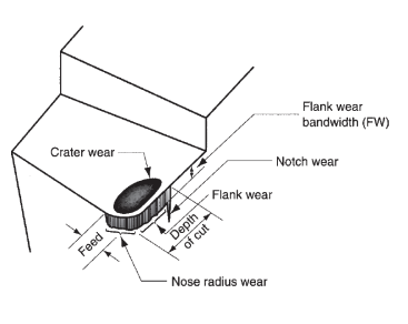
Figure 51: Diagram of worn cutting tool, showing the principal locations and types of wear that occur.
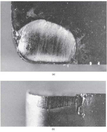
Figure 52: (a) Crater wear and (b) flank wear on a cemented carbide tool, as seen through a toolmaker’s microscope.
Sure options of flank wear may be known. First, extreme condition of flank wear typically seems on the cutting edge at the placement similar to the first surface of the workpart. This is often referred to as notch wear. It happens as a result of the first surface is more durable and/or additional abrasive than the inner material, that might be caused by work hardening from cold drawing or previous machining, sand particles within the surface from casting, or alternative reasons. As a consequence of the more durable surface, wear is accelerated at this location. A second region of flank wear which will be known is nose radius wear; this happens on the nose radius leading into the top cutting edge. The mechanisms that cause wear at the tool–chip and tool–work interfaces in machining may be summarized as follows:
Abrasion:
This is often a mechanical sporting action caused by laborious particles within the work material gouging and removing little parts of the tool. This abrasive action happens in each flank wear and crater wear; it's a major reason for flank wear. Adhesion: Once 2 metals are forced into contact beneath high and temperature, adhesion or welding occur between them. These conditions are gift between the chip and also the rake face of the tool. As the chip flows across the tool, little particles of the tool are broken off from the surface, leading to attrition of the surface.
Diffusion: This is often a method during which exchange of atoms takes place across an in depth contact boundary between 2 materials. Within the case of tool wear, diffusion happens at the tool–chip boundary, inflicting the tool surface to become depleted of the atoms chargeable for its hardness. As this method continues, the tool surface becomes additional liable to abrasion and adhesion. Diffusion is believed to be a principal mechanism of crater wear.
Chemical reactions: The high temperatures and clean surfaces at the tool–chip interface in machining at high speeds may end up in chemical reactions, above all, oxidation, on the rake face of the tool. The oxidized layer, being softer than the parent tool material, is sheared away, exposing new material to sustain the reaction method.
Plastic deformation: Another mechanism that contributes to tool wear is plastic deformation of the cutting edge. The cutting forces engaged on the cutting edge at extreme temperature cause the sting to deform plastically, creating it additional at risk of abrasion of the tool surface. Plastic deformation contributes principally to flank wear. Most of those tool-wear mechanisms are accelerated at higher cutting speeds and temperatures. Diffusion and chemical action are particularly sensitive to elevated temperature.
Tool Life:
As cutting advances, the assorted wear mechanisms lead to increasing levels of wear and tear on the cutting tool. The overall relationship of tool wear versus cutting time is shown in figure. Though the link shown is for flank wear, an identical relationship occurs for crater wear. Three regions will sometimes be known within the typical wear growth curve. The first is that the break-in period, within which the cutting edge wears quickly at the start of its use. This first region happens among the primary few minutes of cutting. The break-in period is followed by wear that happens at a reasonably uniform rate. This can be referred to as the steady-state wear region. In our figure, this region is pictured as a linear operates of your time, though there are deviations from the line in actual machining. Finally, wear reaches tier at which the wear rate begins to accelerate. This marks the start of the failure region, in which cutting temperatures are higher, and also the general potency of the machining method is reduced. If allowed to continue, the tool finally fails by temperature failure. The slope of the tool wear curve within the steady-state region is full of work material and cutting conditions. More durable work materials cause the wear and tear rate (slope of the tool wear curve) to extend. Exaggerated speed, feed, and depth of cut have an identical impact, with speed being the foremost necessary of the 3. If the tools wear curves are aforethought for several totally different cutting speeds. As cutting speed is increased, wear rate will increase therefore the same level of wear and tear is reached in less time.
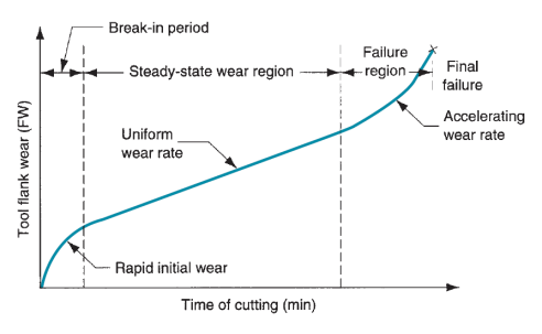
Figure 53: Tool wear as a function of cutting time. Flank wear (FW) is used here as the measure of tool wear. Crater wear follows a similar growth curve.
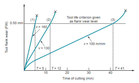
Figure 54: Effect of cutting speed on tool flank wear (FW) for three cutting speeds. Hypothetical values of speed and tool life are shown for a tool life criterion of 0.50-mm flank wear.
Tool life is outlined as the length of cutting time that the tool is often used. Operating the tool till final ruinous failure is a method of shaping tool life. This can be indicated in figure by the tip of every tool wear curve. However, in production, it's usually a disadvantage to use the tool till this failure happens owing to difficulties in re-sharpening the tool and issues with surface quality. As another, tier of tool wear can be elite as a criterion of tool life, and also the tool is replaced when wear reaches that level. A convenient tool life criterion may be a sure flank wears worth, such as 0.5 mm (0.020 in), illustrated because the horizontal line on the graph. When every of the 3 wear curves intersect that line, the lifetime of the corresponding tool is outlined as complete. If the intersection points are projected right down to the time axis, the values of tool life are often known, as we've done.
Taylor Tool Life Equation:
Discovery of this relationship around 1900 is attributable to F.W. Taylor. It will be expressed in equation type and is named the Taylor tool life equation:
VTn = C
Where v = cutting speed, m/min (ft/min); T = tool life, min; and n and C are parameters whose values rely upon feed, depth of cut, work material, tooling (material in particular), and also the tool life criterion used. The worth of n is relative constant for a given tool material, whereas the worth of C depends on tool material, work material, and cutting conditions.
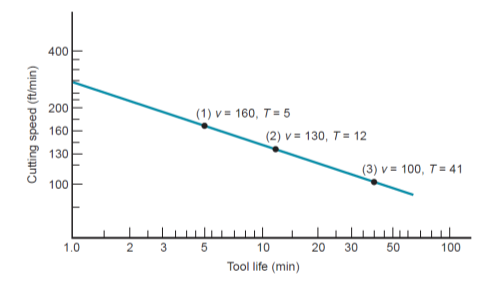
Figure 55: Natural log–log plot of cutting speed vs. Tool life.
Basically, equation states that higher cutting speeds lead to shorter tool lives. Relating the parameters n and C to above figure, n is that the slope of the plot (expressed in linear terms instead of within the scale of the axes), and C is that the intercept on the speed axis. C represents the cutting speed that ends up in a 1-min tool life. The drawback with equation is that the units on the right-hand facet of the equation are not per the units on the left-hand side. To form the units consistent, the equation ought to be expressed within the form
v Tn = C (Trefn)
Where Tref = a reference worth for C. Tref is just one min once m/min (ft/min) and minutes are used for v and T, severally. The advantage of this equation is seen once it's desired to use the Taylor equation with units although m/min (ft/min) and minutes-for example, if cutting speed were expressed as m/sec and power life as sec. During this case, impure would be sixty sec and C would therefore be identical speed worth, though regenerate to units of m/sec. The slope n would have identical numerical worth.
As a result of machining is commonly the producing method that determines the ultimate geometry and dimensions of the part, it's additionally the method that determines the part’s surface texture. Allow us to examine however surface finish is set during a machining operation. The roughness of a machined surface depends on several factors which will be sorted as follows: (1) geometric factors, (2) work material factors, and (3) vibration and machine tool factors. Our discussion of surface finish during this section examines these factors and their effects.
Geometric Factors:
These are the machining parameters that confirm the surface geometry of a machined part. They include: (1) form of machining operation; (2) cutting tool geometry, most significantly nose radius; and (3) feed. The surface geometry that might result from these factors is remarked because the ‘‘ideal’’ or ‘‘theoretical’’ surface roughness, that is that the end that might be obtained within the absence of labor material, vibration, and machine factors. Form of operation refers to the machining method accustomed generate the surface. For instance, peripheral milling, facing edge, and shaping all manufacture a flat surface; but, the surface geometry is totally different for every operation attributable to variations in tool form and also the manner the tool interacts with the surface.
Tool geometry and feed mix to create the surface geometry. The form of the tool purpose is that the necessary tool geometry issue. With an equivalent feed, a bigger nose radius causes the feed marks to be less pronounced, therefore resulting in a much better end. If 2 feeds are compared with an equivalent nose radius, the larger feed will increase the separation between feed marks, resulting in a rise within the price of ideal surface roughness. If feed rate is massive enough and also the nose radius is little enough so the top cutting edge participates in making the new surface, then the top stylish angle can have an effect on surface geometry. During this case, the next ECEA will lead to a higher surface roughness price.
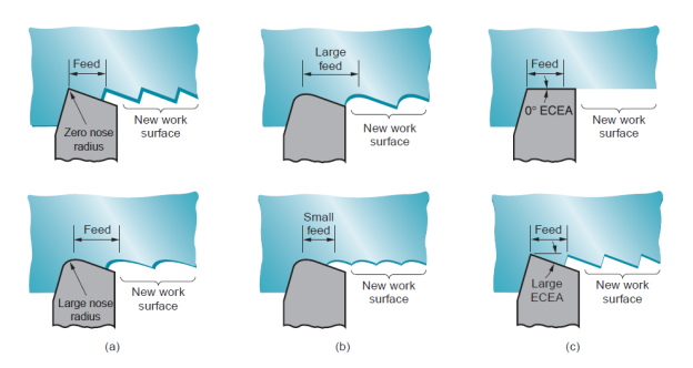
Figure 56: Effect of geometric factors in determining the theoretical finish on a work surface for single-point tools: (a) effect of nose radius, (b) effect of feed, and (c) effect of end cutting-edge angle.
In theory, a zero ECEA would yield a wonderfully swish surface; but, imperfections within the tool, work material, and machining method preclude achieving such a perfect end. The results of nose radius feed may be combined in an equation to predict the best average roughness for a surface made by a single-point tool. The equation applies to operations admire turning, shaping, and planning
Ri = f2/32NR
Where Ri = theoretical arithmetic average surface roughness, millimeter (in); f = feed, millimeter (in); and NR = nose radius on the tool purpose, mm (in). The equation assumes that the nose radius isn't zero which feed and nose radius is going to be the principal factors that confirm the geometry of the surface. The values for Ri will be in units of millimeter (in), which may be regenerate to  (
( -in). The equation may also be accustomed estimate the best surface roughness in face edge with insert tooling, victimization f to represent the chip load (feed per tooth). Equation assumes a pointy cutting tool. Because the tool wears, the form of the cutting purpose changes that is mirrored within the geometry of the surface. For slight amounts of tool wear, the result isn't noticeable. However, once tool wear becomes vital, particularly nose radius wear, surface roughness deteriorates compared with the best values given by the preceding equations.
Work Material Factors:
Achieving the best surface finish isn't doable in most machining operations attributable to factors concerning the work material and its interaction with the tool. Work material factors that have an effect on end include: (1) settled edge effects-as the BUE cyclically forms and breaks away, particles are deposited on the fresh created surface, inflicting it to possess a rough ‘‘sandpaper’’ texture; (2) harm to the surface caused by the chip curling into the work; (3) tearing of the surface throughout chip formation once machining ductile materials; (4) cracks within the surface caused by discontinuous chip formation when machining brittle materials; and (5) friction between the tool flank and also the fresh generated work surface. These work material factors are influenced by cutting speed and rake angle, such a rise in cutting speed or rake angle usually improves surface finish. The work material factors typically cause the particular surface finish to be worse than the best. empirical magnitude relation may be developed to convert the best roughness price into an estimate of the particular surface roughness value. This magnitude relation takes under consideration BUE formation, tearing, and alternative factors. The worth of the magnitude relation depends on cutting speed yet as work material. Figure shows the magnitude relation of actual to ideal surface roughness as a function of speed for many categories of labor material. The procedure for predicting the particular surface roughness during a machining operation is to cypher the best surface roughness price then multiply this value by the magnitude relation of actual to ideal roughness for the suitable category of labor material. This will be summarized as
Ra = raiRi
Where Ra = the calculable price of actual roughness; rai = magnitude relation of actual to ideal surface finish, and Ri = ideal roughness value.
Vibration and machine Factors:
These factors are concerning the machine tool, tooling, and setup within the operation. They embody chatter or vibration within the machine or cutting tool; deflections in the fixturing, typically leading to vibration; and backlash within the feed mechanism, notably on older machine tools. If these machine factors may be decreased or eliminated, the surface roughness in machining are going to be determined primarily by geometric and work material factors represented within the preceding.
Chatter or vibration during a machining operation may end up in pronounced waviness within the surface. Once chatter happens, a particular noise happens which will be recognized by any knowledgeable artisan. Doable steps to scale back or eliminate vibration include: (1) adding stiffness and/or damping to the setup, (2) operational at speeds that don't cause rotary forces whose frequency approaches the natural frequency of the machine system, (3) reducing feeds and depths to scale back forces in cutting, and (4) dynamic the cutter style to scale back forces. Piece of work geometry will generally play a job in chatter. Skinny cross sections tend to extend the probability of chatter, requiring further supports to alleviate the condition.
Properties of the work material have a major influence on the success of the machining operation. These properties and alternative characteristics of the work are typically summarized within the term ‘‘machinability.’’ Machinability denotes the relative ease with that a fabric (usually a metal) may be machined victimization acceptable tooling and cutting conditions. There is numerous criteria accustomed measure machinability, the foremost necessary of that are: (1) tool life, (2) forces and power, (3) surface finish, and (4) easy chip disposal. Though machinability usually refers to the work material, it ought to be recognized that machining performance depends on over simply material. The kind of machining operation, tooling, and cutting conditions also are necessary factors. Additionally, the machinability criterion could be a supply of variation. One material could yield an extended tool life, whereas another material provides a much better surface finish. All of those factors build analysis of machinability troublesome.
Machinability testing typically involves a comparison of labor materials. The machining performance of a take a look at material is measured relative thereto of a base (standard) material. Possible measures of performance in machinability testing include: (1) tool life, (2) tool wear, (3) cutting force, (4) power within the operation, (5) cutting temperature, and (6) material removal rate beneath customary take a look at conditions. The relative performance is expressed as indicant, referred to as the machinability rating (MR).The base material used because the customary is given a machinability rating of 1.00. B1112 steel is commonly used because the base material in machinability comparisons. Materials that are easier to machine than the bottom have ratings larger than 1.00, and materials that are more troublesome to machine have ratings not up to 1.00. Machinability ratings are typically expressed as percentages instead of index numbers
The 3 modes of tool failure permit US to spot three necessary properties needed during a tool material:
Toughness: To avoid fracture failure, the tool material should possess high toughness. Toughness is that the capability of a fabric to soak up energy while not failing. It’s typically characterized by a mix of strength and malleability within the material.
Hot hardness: Hot hardness is that the ability of a fabric to retain its hardness at high temperatures. This is often needed attributable to the high-temperature surroundings during which the tool operates.
Wear resistance: Hardness is that the single most significant property required resisting abrasive wear. All cutting-tool materials should be laborious. However, wear resistance in metal cutting depends on over simply tool hardness, attributable to the opposite tool-wear mechanisms. Alternative characteristics poignant wear resistance embody surface finish on the tool (a drum sander surface means that a lower constant of friction), chemistry of tool and work materials, and whether or not a cutting fluid is employed.
Cutting-tool materials accomplish this mixture of properties in varied degrees. During this section, the subsequent cutting-tool materials are discussed:
(1) Tool steel (high-speed steel) and its predecessors, plain carbon and low alloy steels;
(2) Cast cobalt alloys;
(3) Cemented carbides, cermets, and coated carbides;
(4) Ceramics;
(5) Artificial diamond and cubic boron nitride.
Before examining these individual materials, a short summary and technical comparison are going to be useful. Commercially, the foremost necessary tool materials are tool steel and cemented carbides, cermets, and coated carbides. These 2 classes account for over 90% of the cutting tools utilized in machining operations. The properties are those concerning the necessities of a cutting tool: hardness, toughness, and hot hardness.
A cutting fluid is any liquid or gas that's applied on to the machining operation to enhance cutting performance. Cutting fluids address 2 main problems:
(1) Heat generation at the shear zone and friction zone, and
(2) Friction at the tool–chip and tool–work interfaces.
Additionally to removing heat and reducing friction, cutting fluids offer further advantages, admire laundry away chips (especially in grinding and milling), reducing the temperature of the workpart for easier handling, reducing cutting forces and power needs, rising dimensional stability of the workpart, and rising surface finish.
Kinds of Cutting Fluids:
A spread of cutting fluids is commercially obtainable. It’s acceptable to debate them 1st consistent with operate then to classify them according to chemical formulation.
Cutting Fluid Functions: There are 2 general classes of cutting fluids, similar to the 2 main issues they're designed to address: coolants and lubricants. Coolants are cutting fluids designed to scale back the results of warmth within the machining operation. They need a restricted result on the number of warmth energy generated in cutting; instead, they take away the warmth that's generated, thereby reducing the temperature of tool and piece of work. This helps to prolong the lifetime of the cutting tool. The capability of a cutting fluid to scale back temperatures in machining depends on its thermal properties. Heat energy and thermal conduction are the foremost necessary properties. Water has high heat energy and thermal conduction relative to alternative liquids, that is why water is employed because the base in coolant-type cutting fluids. These properties allow the fluid to draw heat off from the operation, thereby reducing the temperature of the cutting tool. Coolant-type cutting fluids appear to be best at comparatively high cutting speeds, during which heat generation and high temperatures are issues. They’re best on tool materials that are most liable to temperature failures, admire high speed steels, and are used oft in turning and edge operations, during which massive amounts of warmth are generated.
Lubricants are typically oil-based fluids (because oils possess sensible lubricating qualities) developed to scale back friction at the tool–chip and tool–work interfaces. Lubricator cutting fluids operate by extreme pressure lubrication, a special type of lubrication that involves formation of skinny solid salt layers on the recent, clean metal surfaces through chemical action with the lubricator. Compounds of sulfur, chlorine, and phosphorus within the lubricator cause the formation of those surface layers, that act to separate the 2 metal surfaces (i.e., chip and tool).These extreme pressure films are significantly more effective in reducing friction in metal cutting than standard lubrication, that is predicated on the presence of liquid films between the 2 surfaces. Lubricant-type cutting fluids are best at lower cutting speeds. They have a tendency to lose their effectiveness at high speeds as a result of the motion of the cut these speeds prevents the cutting fluid from reaching the tool–chip interface. Additionally, high cutting temperatures at these speeds cause the oils to vaporize before they'll lubricate. Machining operations admire drilling and sound typically like lubricants. In these operations, settled edge formation is unintelligent, and force on the tool is reduced. Though the principal purpose of a lubricator is to scale back friction, it additionally reduces the temperature within the operation through many mechanisms. First, the precise heat and thermal conduction of the lubricator facilitate to get rid of heat from the operation, thereby reducing temperatures. Second, as a result of friction is reduced, the warmth generated from friction is additionally reduced. Third, a lower constant of friction means that a lower friction angle. According to Merchant’s equation, a lower friction angle causes the shear angle to extend, thus reducing the number of warmth energy generated within the shear zone. There's usually overlapping result between the 2 kinds of cutting fluids. Coolants are developed with ingredients that facilitate scale back friction. And lubricants have thermal properties that, though not nearly as good as those of water, act to get rid of heat from the cutting operation. Cutting fluids (both coolants and lubricants) manifest their result on the Taylor tool life equation through higher C values. Will increase of 10% to 40% are typical. The slope n isn't considerably affected.
Chemical Formulation of Cutting Fluids: There are four classes of cutting fluids consistent with chemical formulation:
(1) Cutting oils,
(2) Blended oils,
(3) Semi-chemical fluids, and
(4) Chemical fluids.
All of those cutting fluids offer each fluid and lubricating functions. The cutting oils are best as lubricants, whereas the opposite 3 classes are simpler as coolants as a result of their primarily water.
Cutting oils are supported oil derived from crude, animal, marine, or vegetable origin. Mineral oils (petroleum based) are the principal kind attributable to their abundance and usually fascinating lubricating characteristics. To realize most lubricity, many kinds of oils are typically combined within the same fluid. Chemical additives also are mixed with the oils to extend lubricating qualities. These additives contain compounds of sulfur, chlorine, and phosphorus, and are designed to react chemically with the chip and power surfaces to create solid films (extreme pressure lubrication) that help to avoid metal-to-metal contact between the two.
Blended oils contain oil droplets suspended in water. The fluid is created by mixing oil (usually mineral oil) in water victimization emulsifying agent to push blending and stability of the emulsion. A typical magnitude relation of water to oil is 30:1. Chemical additives supported sulfur, chlorine, and phosphorus are typically accustomed promote extreme pressure lubrication. As a result of they contain each oil and water, the blended oils mix cooling and lubricating qualities in one cutting fluid.
Chemical fluids are chemicals during a water answer instead of oils in emulsion. The dissolved chemicals embody compounds of sulfur, chlorine, and phosphorus, and wetting agents. The chemicals are meant to produce some extent of lubrication to the answer. Chemical fluids offer sensible fluid qualities however their lubricating qualities are not up to the opposite cutting fluid sorts. Semi-chemical fluids have little amounts of blended oil additional to extend the lubricating characteristics of the cutting fluid. In effect, they're a hybrid category between chemical fluids and blended oils.
Numerical control (NC) could be a type of programmable automation during which the mechanical actions of a bit of apparatus are controlled by a program containing coded alphanumeric knowledge. The info represents relative positions between a work head and a workpart. The work head could be a tool or alternative process part, and also the workpart is that the object being processed. The operational principle of NC is to manage the motion of the work head relative to the workpart and to control the sequence during which the motions are applied. The primary application of numerical control was in machining and this is often still a very important application space. NC machine tools are shown in figures.
The Technology of Numerical Control:
During this section we have a tendency to outline the elements of a numerical system, and then proceed to explain the axis system and motion controls.
Elements of NC System:
A numerical system consists of 3 basic components: (1) part program, (2) machine control unit, and (3) process instrumentation. The part program (the term normally utilized in machine technology) is that the elaborated set of commands to be followed by the process instrumentation. It’s the program of directions within the NC system. Every command specifies an edge or motion that's to be accomplished by the work head relative to the workpart. An edge is outlined by its x-y-z coordinates. In machine applications, further details within the NC program embody spindle rotation speed, spindle direction, feed rate, tool amendment directions, and alternative commands concerning the operation. The part program is ready by a section computer user, someone who is aware of the main points of the programing language and additionally understands the technology of the process instrumentation.
The machine control unit (MCU): in fashionable NC technology could be a personal computer that stores and executes the program by changing every command into actions by the process instrumentation, one command at a time. The MCU consists of each hardware and software system. The hardware includes the personal computer, elements to interface with the process instrumentation, and sure feedback control components. The software system within the MCU includes system software, calculation algorithms, and translation software system to convert the NC part program into a usable format for the MCU. The MCU additionally permits the part program to be altered just in case the program contains errors, or changes in cutting conditions are needed. As a result of the MCU could be a laptop, the term laptop numerical control (CNC) is commonly accustomed distinguish this kind of NC from its technological predecessors that were based mostly entirely on hard-wired physics. The process instrumentation accomplishes the sequence of processing steps to remodel the beginning workpart into a completed part. It operates beneath the control of the MCU consistent with the directions within the part program.
Coordinate system and Motion control in NC:
A coordinate axis system is employed to specify positions in numerical control. The system consists of the 3 linear axes (x, y, z) of the co-ordinate system, and 3 motion axes (a, b, c). The motion axes are accustomed rotate the workpart to gift totally different surfaces for machining, or to orient the tool or work head at some angle relative to the part. Most NC systems don't need all six axes. The best NC systems (e.g., plotters, pressworking machines for flat sheet-metal stock, element insertion machines) are positioning systems whose locations may be outlined in an x-y plane. Programming of those machines involves specifying a sequence of x-y coordinates. Against this, some machine tools have five-axis control to form complicated workpart geometries. These systems usually embody 3 linear axes and 2 motion axes.
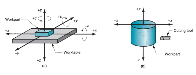
Figure 57: Coordinate systems used in numerical control: (a) for flat and prismatic work, and (b) for rotational work.
These systems are related to turning operations on NC lathes. Though the work rotates, this is often not one of the controlled axes in a standard NC turning system. The cutting path of the tool relative to the rotating piece of work is outlined within the x-z plane, as shown in our figure. In several NC systems, the relative movements between the process tool and also the workpart are accomplished by fixing the part to a work table then dominant the positions and motions of the table relative to a stationary or semi stationary work head. Most machine tools and element insertion machines are supported this methodology of operation. In alternative systems, the workpart is control stationary and also the work head is rapt on 2 or 3 axes. Flame cutters, x-y plotters, and coordinate measure machines operate during this mode.
Motion control systems supported NC may be divided into 2 types: (1) point-to-point and (2) continuous path. Point-to-point systems additionally referred to as positioning systems, move the work head (or workpiece) to a programmed location with no regard for the trail taken to induce thereto location. Once the move is completed, some process action is accomplished by the work head at the placement, admire drilling or punching a hole. Thus, the program consists of a series of purpose locations at that operations are performed. Continuous path systems offer continuous coincident control of over one axis, therefore dominant the trail followed by the tool relative to the part. This permits the tool to perform a method whereas the axes are moving, facultative the system to come up with angular surfaces, two-dimensional curves, or three-dimensional contours within the workpart. This operational theme is needed in drafting machines, sure edge and turning operations, and flame cutting. In machining, continuous path control additionally goes by the name contouring. a very important side of continuous path motion is interpolation, that cares with hard the intermediate points on a path to be followed by the work head relative to the part. 2 common kinds of interpolation are linear and circular. Linear interpolation is employed for line methods, during which the part computer user specifies the coordinates of the start purpose and finish point of the line yet because the feed rate to be used. The interpolator then computes the travel speeds of the 2 or 3 axes that may accomplish the desired mechanical phenomenon. Circular interpolation permits the work head to follow a circular arc by specifying the coordinates of its starting and finish points beside either the middle or radius of the arc. The interpolator computes a series of little line segments that may approximate the arc at intervals an outlined tolerance.
Another side of motion control cares with whether or not the positions within the system are outlined fully or incrementally. In absolute positioning, the work head locations are forever outlined with reference to the origin of the axis system. In progressive positioning, consequent work head position is outlined relative to this location.
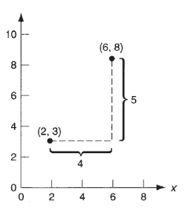
Figure 58: Absolute vs. Incremental positioning. The work head is at point (2,3) and is to be moved to point (6,8). In absolute positioning, the move is specified by x=6, y=8; while in incremental positioning, the move is specified by x = 4, y = 5.
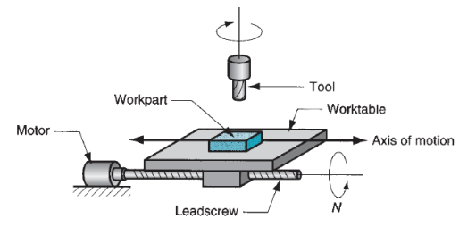
Figure 59: Motor and lead screw arrangement in an NC positioning system.
References:
1. Kalpakjian and Schmid, Manufacturing processes for engineering materials (5th Edition)-Pearson India, 2014.
2. Mikell P. Groover, Fundamentals of Modern Manufacturing: Materials, Processes, andSystems.
3. Manufacturing Technology by P.N. Rao., MCGRAW HILL INDIA.
4. Materials and Manufacturing by Paul Degarmo.
5. Manufacturing Processes by Kaushish, PHI.