Unit 1
Electromagnetism
Coulombs Law of Electromagnetic
1st Law- Like poles repels and unlike poles attract
2nd Law- is the force of attraction or repulsion 2 pole a magnetic field in directly proportional to the product of the field strength and inversely proportional to the square of the distance between then i.e. F X 
When K instant which depends upon nature of surrounding medium to the poles and m1 m2 are the pole strength.
Concept of Electromagnet
They are used to decide the direction of current and magnetic field
* Direction of current:
1) Dot 2) Cross
* Direction of magnetic field-
1) Right hand thumb
2) Cork Screw Rule
Direction of current:
- Dot Convention:
|
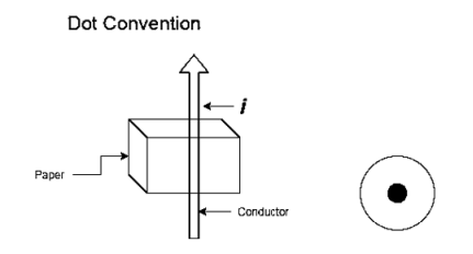
If the current is flowing through a conductor is moving towards the observer and out of the plane of paper, then this direction is indicated by Dot.
2. Cross Convention:
|
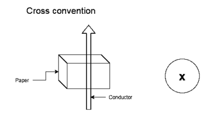
If the current is flowing through conductor moving away from the observer and into the plane of paper, then this current direction is indicated by cross.
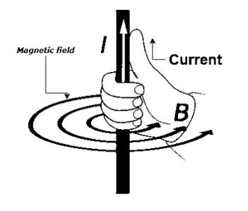
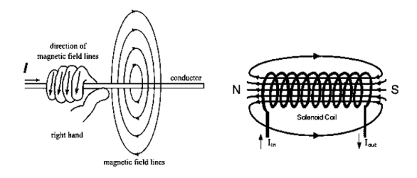
If a straight conductor is held in right hand such that thumb indicates the direction of current and curled fingers indicates the direction of magnetic field
|
|
When straight conductor carries a current it produces a magnetic field all along its length. The lines of force are in the form of concentric circles in the planes right angle to the conductor.
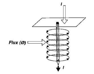
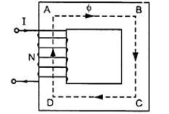
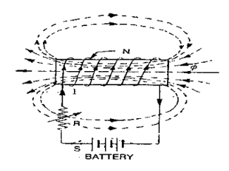
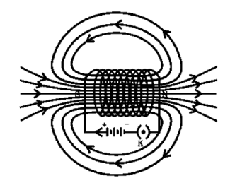
Magnetic field due to solenoid
|
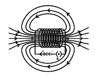
When the current is passed through the solenoid. The magnetic field is produced as show in above fig.
It is produced outside as well as inside the core of solenoid.
Note that direction of field is reversed due to current direction.
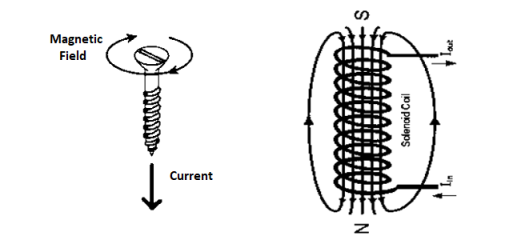
Rules to find polarity of solenoid
- Right Hand Thumb Rule
|
2. Cork Screw Rule
|
- Magnetic motive force MMF: It is the force that is required for production of flux
MMF = No. of turns x current
= N x I
= Ampere Turns
=AT
2. Magnetic flux: The total no of lines of force in a magnetic field denoted by Ø and measured in Weber’s.
3. Magnetic flux density [B] =The flux per unit area measured in a plane perpendicular to the flux is defined as the flux density.
It is measured in tesla [T] and donated by B
B = Tesla / wb /
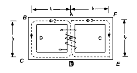
4. Reluctance - It is defined as the opposition to the flow of flux in a material
Reluctance is denoted by S and measured in AT/wb or Siemens
S = ɺ/ μ₀μᵣₐ - AT/wb
It can also be defined as the ratio of (MMF) to the magnetic flux (Ø)
S = |

5. Permeability- It is defined as the ability of a material to carry the flux lines. There are three permeability’s: -
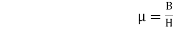
- Absolute Permeability [μ]:
It is defined as the ratio of magnetic flux density [B] in a particular medium to the magnetic field strength [H] which produces that flux density it is denoted by μ and measured in henry per meter
 H/M
H/M
2. Permeability of force space or vacuum:
It is ratio of magnetic flux density of force space or vacuum to the magnetic field strength it is denoted by μ0 and measured henry / meter
 H/M
H/M
The value of μₒ is always constant
μₒ= 4λ x 10-7 H/M
3. Relative Permeability:
It is defined as the ratio flux density in a particular medium to the flux density in air or vacuum conditions the same magnet under identical conditions denoted by μ
μ Expression of μμ= μ₀ = nowμ
μ = μ₀μᵣ |


6. Magnetic field strength / intensity / magnetising force
It is the force experienced by a unit north poles placed at that point in the magnetic field Denoted by H
Measured in Newtown / wb or AT/n H = H = Permeance: It is defined as the reciprocal of reluctance the permeance represents the property of magnetic material to allow the flux to pass through it. Permeance = |


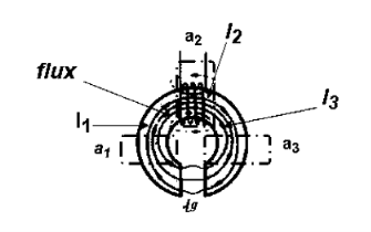
- Derivation of series magnetic current with air gap
In series magnetic circuit flux  is same in each part of circuit
Consider a composite magnetic circuit made from different material of lengths ɻ1,ɻ2, and ɻ3 cross sectional area a1, a2 And a3 and relative permeability’s  1 ,
1 ,  2 ,
2 ,  3 resp. with an air gap of length ɻɡ
|
We know that S =
| ||
But S =
Now B =
but B=μH
| ||


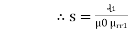


A magnetic circuit which has more than one path for flux called parallel magnetic circuit
|
Mean length ABCDA = ɻ₁, and ADEFA = ɻ₂
Mean length path for central limb = ɻc
Reluctance ABCDA = S1, ADEFA = S2
And central limb = SC
Now total mmȴ = N 
 i.e. mmf =
For path ABC AD
N Where S1 = Where
Total mmȴ = mmȴ by central limb + mmȴ required by any one of outer limb = Ø sc + [Ø1S1 or Ø2 S2] As mmf across parallel branch is same |


 Ø1 S1 = Ø2 S2
Hence while calculating total mmf, the mmf of only one of 2 parallel branches must be considered.
Electrical | Magnetic
|
|
|
Current flow of electrons Unit- Ampere | flux: magnetic lines of force Unit- Weber
|
I =
| Ø = MMF/S
|
EMF: driving force for current | MMF driving force for flux: AT
|
Resistance: opposition to the Flow of current | Reluctance: opposition to the flow of flux |
R = ƍ | s =
|
I = | ɸ
|
Conductance = | Permeance =
|
Current density ʆ = | Flux density B =
|
Electric filed Intensity E = | Magnetic field intensity H =
|
Voltage drop V = IR | MMF Drop = Ø.S
|
It is closed path for current | It is closed path for flux
|
Kirchhoff’s current and voltage Law applicable to electric circuit | Kirchhoff’s flux and MMF laws are applicable to mag circuit
|


 Electric Magnetic
- Current is actual flow of electrons 1. Flux does not flow in the mag circuit
- Energy is required to produce the 2. Energy is required to produce
Current and maintain it flux but not for its maintenance
3. Current does not pass through air 3. Flux can pass through air
4. Resistance is independent of the 4. Reluctance of current changes with of the current flux
5.  5.
5. 
6. Current is reduced to zero after 6. Residual flux persists after removal of removal of emf mmf
7.  7.
7. 
Current density Flux density
8.  8.
8. 
9. Conductance =  9. Permeance =
10. Electric field Intensity  10. Magnetic filed Intensity
11. emf drop = I x R 11. mmf drop = Ø x S
It involves the interaction of magnetic field and current carrying conductor placed in it. The operation sequence is as follow
- Development of individual field
- Interaction of two magnetic fields
- Force exerted on the conduction
|
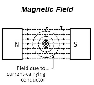
- Development of individual field
- Let a straight conductor is placed in the magnetic field produced by permanent magnet.
- Let current flowing through the conductor is out of the plane of the paper.
- The magnetic field produced by conductor is shown above
2. Interaction of two magnetic field
|
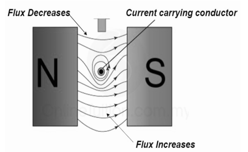
At the top flux lines produced by the magnet and conductor are in opposite direction to each other and hence cancel each other.
At the bottom individual fields are in same direction they will add each other.
3. Force excreted on the conductor
|
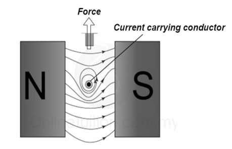
The lines of force on the bottom exert a force on the conductor in the upward direction as shown above.
Hence mechanical force is exerted on the conductor from high flux line area towards the low flux line area (top).
The magnetically of force experienced by the current carrying conductor placed in a magnetic field is given by
F = B I ɺ sin Ɵ newton Where F = Force exerted B = Flux density ɺ = length of conductor I = current Ɵ = angle between conductor and magnetic field. | ||
| ||
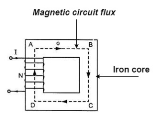
The magnetic circuit can be defined as the closed path traced by magnetic line of force such magnetic circuit is associated with different magnetic quantities such as MMF, flux, flux density, magnetic field strength
we know that H = and B = μ H put value of H
But μ = μₒμ
But B = Ø = Numerical on F = B I ɻ sin |


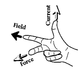
Flemings left Hand Rule for direction of current (for Motor)
|
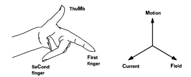
If the first 3 fingers of left hand are held mutually at right angle to each other. First finger indicates magnetic field middle finger indicates direction of current and thumb indicated force exerted.
- First law: whenever flux linkage with the coil changes an emf is induced in that conductor
- Second law: the magnitude of induced emf is equal to the rate of change of flux linkage
Explanation: suppose a coil has n turns and flux through it change from initial value of Ø1 to Ø2 in line t sec
Initial flux linkage = N Ø
Final flux linkage = NØ2
|


Putting the above equation in differential form
e = rate of change of flux linkage
| ||
The direction of this induced emf is given by lenis law which states the polarity of induced emf is always such that it tends to set up a current which flow in such a direction so as to oppose the cause that produces it.
| ||


Direction of Induced EMF can be given by Flemings Right Hand Rule [For Generator]
|
Stretch the first 3 fingers of Right Hand perpendicular to each other If the thumb indicates direction of motion of conductor, first/ fore fingers indicates direction of flux then the middle finger indicates direction of induced EMF.
Induced EMF
Whenever flux linking a conductor changes an emf is induced in it. This change in flux linkage can be trough about in the following 2 ways
- The conductor is moved in a stationary magnetic field in such a way that the flux linking is changes in magnitude. The emf induced in this is called dynamically induced emf.
- The conductor is stationary and magnetic field is moving or changing the emf induced in this way is called statically induced emf.
Statically Induce EMF:
This is technique of generating an emf but here neither the conductor nor the magnetic field are physically moved for EMF generation both are stationary.
- The flux linkage taking place with conductor is changed by changing the magnitude of the current that produces magnetic field.
e.g. Transformers
Statically EMF is subdivided in 2 types:
- Self-Induced EMF
- Mutual Induced EMF
Self-Induced EMF
|
The EMF induced in coil due to change of its own flux linked with it is called as self-Induced EMF
The change in flux is brought by changing the current flowing in coil {using variable resister ‘R’ / or using ac supply}
Magnitude of self-Induced EMF
Consider a coil haring n Turns carrying a current I amperes ɡȴ the current in the coil changes the flux linkage of the coil also changes which sets up a self-induced EMF in the coil
We know that Ø x I
As Rate of flux linkage = K x rate of changes of current
Now e = - N Put value of |
Where L = |


The property of coil that opposes any changes in the amount of current flowing through it is called as well Inductance.
Coefficient of self-Inductance: Now L = We know that Ø = Ø =
S decreases L Increases L is proportional to square of turn NL |


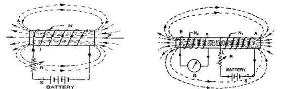
Mutually Induced EMF
|
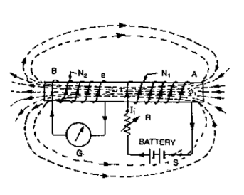
The emf induced in the coil due to change in current in the neighbouring coil is called as mutually induced EMF
Consider 2 coil 1 and 2 placed closed, adjacent to each other
Current  1 (Variable current) flows in coil 1, flux Ø1 is set upand a part ofthis flux (Ø2) links coil 2. The EMF induced in coil 2 is termed as mutually induced EMF whereas EMF induced in coil 1 is termed as self-induced EMF.
Mutually induced emf is given by e2 = -N2 we know that Ø2 x Ø2=K Rate of change of flux in coil 2 = k x change in current in coil 1
Now e2 = - N2 Replacing value of
|


Where
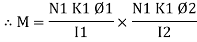
M =  mutual Inductance
Coefficient of mutual Inductance M = Now
|


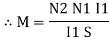

B) Dynamically Induced EMF
|
The conductor is moved in a stationary magnetic field in such a way that the flux linking changes in magnitude. The EMF induced in the coil is called as dynamically induced EMF.
Consider a conductor length  moving in the air gap between the poles of magnet.
ɡȴ the plane of the motion of conductor is parallel to the plane of magnetic field, there is no cutting of flux lines and there cannot be any induced EMF in the conductor Fig (a).
The motion of conductor is premedical to the flux then the whole length of conductor cuts the flux line and maximum induced EMF is produced (Fig B)
Magnitude of dynamically Induced EMF:
Consider a conductor moving with velocity such that its plane of motion or direction of velocity is perpendicular to direction of flux lines as shown in (Fig)
Let B = Flux Density
ɻ = Active length
V = Velocity
Let this conductor is moved through distance dx in small interval dt
According to faradays law e = -N consider (-N = 1)
e = B but |


 e = B
e = B  ɻ
ɻ V
V
But the conductor is moving with a velocity but at a certain angle  measured with respect to direction of field.
Magnitude of induced EMF 
Differentiate statically and dynamically induced EMF

Statically Dynamically
- Coil or conductor stationary field 1. Conductor / coil is moving field Stationary Stationary.
- EMF induced due to flux linking 2. EMF induced due to flux cutting
In its own coil.
3. emf = m  3.
3. 
es = L 
4. magnitude of EMF induced 4. Magnitude of EMF induced on rate of depends change of flux  Depends on flux cutting.
5. Direction of EMF induced given 5. By Flemings Right hmd rule
Len’s law
6. E.g. Transformers 6. E.g. Rotating machines like
dc/ac machines
|
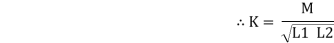
Coefficient of coupling K
It is the fraction of magnetic flux produced by the current in one coil that links the other.
Consider 2 coils having number of turns N1 and N2 respectively: When a current
K1 =
Put the value of We get Now if current
Let K2=
| ||
Put the value of
Multiply A
Rearranging the terms
L2= Let K1 = K2 = K
Taking out roots
| ||


|
We know that self-induced EMF e = - L |

- The emf opposes the change in current
 acc. To Lenzs law
 - To overcome this opposition, the source i.e. ac source has to provide some energy to the circuit.
- This energy is stored in magnetic field as potential energy.
- When the s/w “S” is open current starts decreasing from I to O again here faradays Law is applied as emf is induced [changing
 chenging Ø
  EMF
EMF - According to Lenz’s Law:
The emf opposes the change in current now the stored energy will be used to stop the reduction of circuit and try to maintain current to its original value
But v = (-e) refer point ② We know that E = P
Since current changing from o to
= L E=
L =
|


Now N  = MMF = H
Now V =
Or E/V Or E/V
|


Reference Books:
- H Cotton, Electrical technology, CBS Publications
- L. S. Bobrow, ―Fundamentals of Electrical Engineering‖, Oxford University Press, 2011.
- E. Hughes, ―Electrical and Electronics Technology‖, Pearson, 2010.
- D. C. Kulshreshtha, ―Basic Electrical Engineering‖, McGraw Hill, 2009.


