Unit 3
Single phase AC circuit
3 Basic element of AC circuit.
1] Resistance
2] Inductance
3] Capacitance
Each element produces opposition to the flow of AC supply in forward manner.
Reactance
It is opposition to the flow of an AC current offered by inductor. XL = ω L But ω = 2 ᴫ F
It is measured in ohm
2. Capacitive Reactance (Xc) It is opposition to the flow of ac current offered by capacitor Xc = Measured in ohm
|


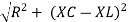
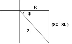
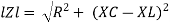
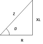
Impedance (Z) The ac circuit is to always pure R Pure L and pure C it well attains the combination of these elements. “The combination of R1 XL and XC is defined and called as impedance represented as Z = R +i X Ø = 0 |
 only magnitude
R = Resistance, i = denoted complex variable, X =Reactance XL or Xc
Polar Form Z = Where |


 Measured in ohm
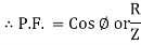
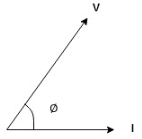
Power factor (P.F.)
|
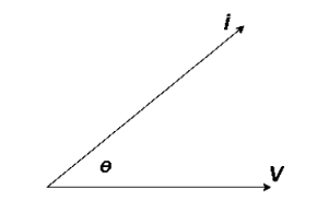
It is the cosine of angle between voltage and current
If Ɵis –ve or lagging (I lags V) then lagging P.F.
If Ɵ is +ve or leading (I leads V) then leading P.F.
If Ɵ is 0 or in phase (I and V in phase) then unity P.F.
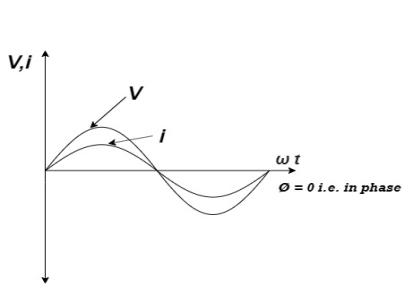
Ac circuit containing pure resisting
|
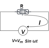
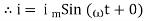
Consider Circuit Consisting pure resistance connected across ac voltage source V = Vm Sin ωt ① According to ohm’s law i = But Im = | ||
| ||


Phases diagram
From ① and ② phase or represents RMD value.
|
Power P = V. i Equation P = Vm sin ω t Im sin ω t |
P = Vm Im Sin2 ω t P =
Constant fluctuating power if we integrate it becomes zero
Average power Pavg = Pavg = |


Pavg = Vrms Irms |
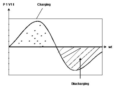
Power ware form [Resultant]
|

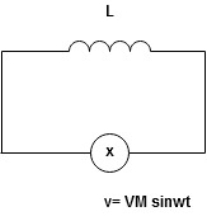
Ac circuit containing pure Inductors
|
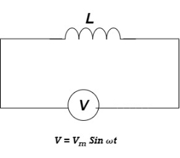
Consider pure Inductor (L) is connected across alternating voltage. Source
V = Vm Sin ωt |
When an alternating current flow through inductance it set ups alternating magnetic flux around the inductor.
This changing the flux links the coil and self-induced emf is produced
According to faradays Law of E M I e = | ||||
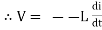
at all instant applied voltage V is equal and opposite to self-induced emf [ lenz’s law] V = -e
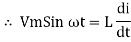
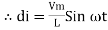
But V = Vm Sin ωt
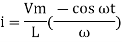
Taking integrating on both sides
| ||||
but sin (–
And Im=
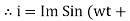
= -ve | ||||


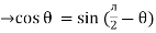
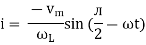


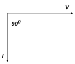
= lagging
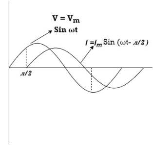
= I lag v by 900
Waveform:
|

Phasor:
|
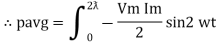
Power P = Ѵ. I = Vm sin wt Im sin (wt = Vm Im Sin wt Sin (wt –
And Sin (wt - Sin (wt –
The average value of sin curve over a complete cycle is always zero
|


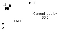
Ac circuit containing pure capacitors:
|
Consider pure capacitor C is connected across alternating voltage source
Ѵ = Ѵm Sin wt
Current is passing through capacitor the instantaneous charge ɡ produced on the plate of capacitor
ɡ = C Ѵ
ɡ = c Vm sin wt | |
the current is rate of flow of charge
i = c Vm w cos wt then rearranging the above eqth. i =
i = but
= leading | |


= I leads V by 900
Waveform:
|
Phase
|
Power P= Ѵ. i = [Vm sinwt] [ Im sin (wt + X/2)] = Vm Im Sin wt Sin (wt + X/2)]
|

|
Series R-L Circuit
|
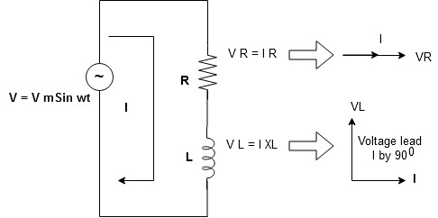
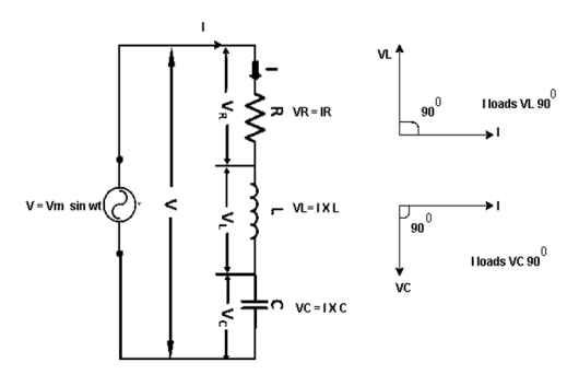
Consider a series R-L circuit connected across voltage source V= Vm sin wt
As some I is the current flowing through the resistor and inductor due do this current voltage drops arcos R and L R
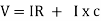
V = IR + I X L
|


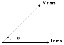
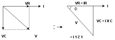
Take current as the reference phasor: 1) for resistor current is in phase with voltage 2) for Inductor voltage leads current or current lags voltage by 90 0.
|
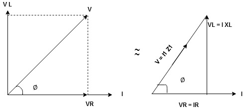
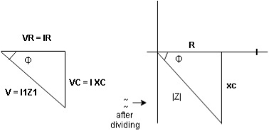
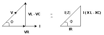
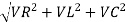
For voltage triangle
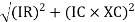
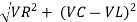
Ø is power factor angle between current and resultant voltage V and V =
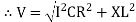
V =
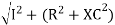
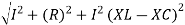
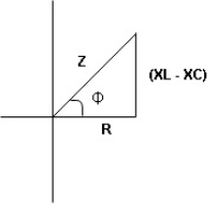
where Z = Impedance of circuit and its value is |


Impedance Triangle
Divide voltage triangle by I
|
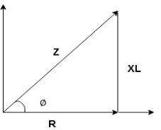
Rectangular form of Z = R+ixL and polar from of Z = (+ j X L + Where
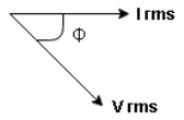
Current Equation: From the voltage triangle we can sec. that voltage is leading current by Or i = |


|
Resultant Phasor Diagram from Voltage and current eqth.
|
Wave form
|

Power equation P = V.I. P = Vm Sin wt Im Sin wt – Ø P = Vm Im (Sin wt) Sin (wt – Ø) P = Since 2 sin A Sin B = Cos (A-B) – Cos (A+B) P =
①② | ||
Average Power pang = Since ② term become zero because Integration of cosine come from 0 to 2ƛ | ||


 pang = Vrms Irms cos Ø watts.
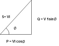
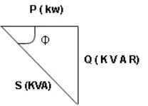
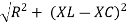
Power Triangle:
|
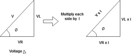
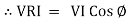
From VI = VRI + VLI B Now cos Ø in
Similarly Sin
Apparent Power Average or true Reactive or useless power Or real or active -Unit (VI) Unit (Watts) C/W (VAR) denoted by (Ø) Denoted by [S] denoted by [P] |


Power  for R L ekt.
|
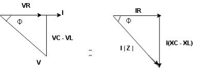
Series R-C circuit
|
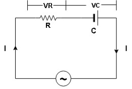
V = Vm sin wt
VR

 I
I
|
- Consider a series R – C circuit in which resistor R is connected in series with capacitor C across a ac voltage so use V = VM Sin wt (voltage equation).
- Assume Current I is flowing through
R and C R and C And C
|


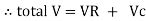

 V =
V =  lZl
lZl
Voltage triangle: take current as the reference phasor 1) for resistor current is in phase with voltage 2) for capacitor current leads voltage or voltage lags behind current by 900
|
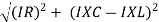
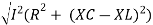
Where Ø is power factor angle between current and voltage (resultant) V And from voltage V = V = V = V = Where Z = impedance of circuit and its value is lZl = |


Impendence triangle:
Divide voltage  by
by  as shown
|
Rectangular from of Z = R - jXc Polar from of Z = lZl L - Ø ( - Ø and –jXc because it is in fourth quadrant ) where lZl = and Ø = tan -1 |


Current equation: from voltage triangle we can see that voltage is lagging current by Ø or current is leading voltage by Ø
Or i = |


|

Resultant phasor diagram from voltage and current equation
|
Resultant wave form :
|

Power Equation: P = V. I P = Vm sin wt. Im Sin (wt + Ø) = Vm Im sin wt sin (wt + Ø) 2 Sin A Sin B = Cos (A-B) – Cos (A+B)
|


Average power
pang = since 2 terms integration of cosine wave from 0 to 2ƛ become zero
|


Power triangle RC Circuit:
|
R-L-C series circuit
|
Consider ac voltage source V = Vm sin wt connected across combination of R L and C. when I flowing in the circuit voltage drops across each component as shown below.
VR = IR, VL = I  L, VC = I
  C
C
- According to the values of Inductive and Capacitive Reactance I e XL and XC decides the behaviour of R-L-C series circuit according to following conditions
① XL> XC, ② XC> XL, ③ XL = XC
① XL > XC: Since we have assumed XL> XC
 Voltage drop across XL> than XC
 VL> VC A
- Voltage triangle considering condition A

|
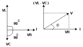
VL and VC are 180 0 out of phase.
Therefore, cancel out each other
 Resultant voltage triangle
|
Now V = VR + VL + VC From voltage triangle V =
|


Impendence  : divide voltage
|
Rectangular form Z = R + j (XL – XC) Polor form Z = Where And Ø = tan-1 |


- Voltage equation: V = Vm Sin wt
- Current equation
i = i = as VL
| |
| |


- XC
 XL :Since we have assured XC
  XL
XL
 the voltage drops across XC
  than XL
 XC
XC  XL (A)
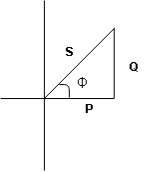
 voltage triangle considering condition (A)
|
 Resultant Voltage
|
Now V = VR + VL + VC  phases sum and VL and VC are directly in phase opposition and VC
 VL
VL  their resultant is (VC – VL)
From voltage V = V =
|


 Impedance
  : Divide voltage
|
Polar form : Z = Where And Ø = tan-1 –
as VC since i =
|


- Power
 :
:
|
- XL= XC (resonance condition):
ɡȴ XL= XC then VL= VC and they are 1800 out of phase with each other  they will cancel out each other and their resultant will have zero value.
Hence resultant V = VR and it will be in phase with I as shown in below phasor diagram.
|
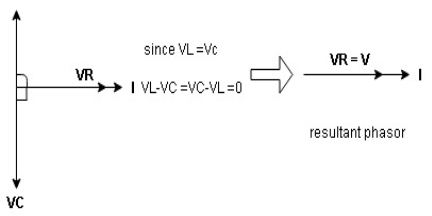
From above resultant phasor diagram V =VR + IR Or V = I Because lZl + R Thus Impedance Z is purely resistive for XL = XC and circuit current will be in phase with source voltage.
ie pang = Vrms I rms cos Ø = 1 cos o = 1 |


maximum power will be transferred by condition. XL = XC
Definition: it is defined as the phenomenon which takes place in the series or parallel R-L-C circuit which leads to unity power factor
Voltage and current in R – L - C ckt. Are in phase with each other
Resonance is used in many communicate circuit such as radio receiver.
Resonance in series RLC series resonance in parallel RLC anti resonance / parallel resonance.
- Condition for resonance XL = XC
- Resonant frequency (Fr) : for given values of R-L-C the inductive reactance XL become exactly equal to the capacitive reactance Xc only at one particular frequency. This frequency is called as resonant frequency and denoted by (fr)
- Expression for resonant frequency(fr) : we know thet XL = 2ƛ FL - Inductive reactance
Xc =  - capacitive reactance
At a particular frequency ȴ = fr, the Inductive and capacitive reactance are exactly equal
Ie
And |


Quality factor / Q factor
The quality of resonance circuit is measured in terms of efficiency of L and C to stare energy and the efficiency of L and C to store energy as measured in terms of a factor called quality factor or Q factor it is expressed as
Q =  and Q =
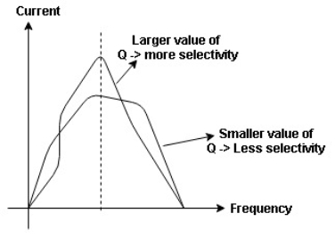
The sharpness of tuning of R-L-C series circuit or its selectivity is measured by value of Q. as the value of Q increases, sharpness of the curve also increases and the selectivity increases.
|
|
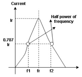
Bandwidth (BW) = f2 = b1
 and
and  are the frequency at which the power delivered to the resistor is reduced to 50% of the power delivered to it at resonance
  these frequency are called as half power frequency
Bw = fr/Q
Two impedances in parallel
|
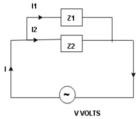
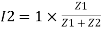
I1 an I2 can be founded using current division rules It states that the current in one branch is the products, ratio of total current and opposite branch (impedance / reactance / resistance) to the total (impedance / reactance / resistance)
|


S = V
2. In kilo – K. V. A. |


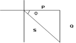
3. Real power / true power / active power / useful power: [P] it is defined as the product of rms value active component or it is the average power or actual power consumed by the resistive part (R) in the given combinational circuit
It is measured in watts
P = VI Cos Ø watts /km where Ø is the power factor angle
4. Reactive power / Imaginary / useless power [Q]
It is defined as the product of voltage current and sine of angle between V and
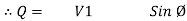

Volt Amp Relative
 Unit – V A R
 Power triangle
|
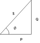
- As we know power factor is cosine of angle between voltage and current
i e P.F. = Cos 
|
in other words also we can derive it from impedance triangle
now consider Impedance triangle in R – L- ckt.
|
From
|


AC parallel circuit:
|
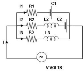
Total I = I1 + I2 + I3 As parallel circuit I = I1 + I2 + I3 |

=
|


Admittance is defined as reciprocal of the impedance (Z)
It is denoted by Y and its unit Siemens (S)
 Admittance Y =
|
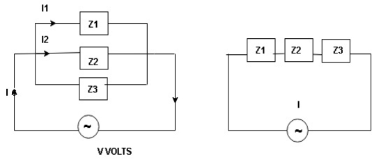
I = I1 + I2 + I3 | ||
Y = Y1 + Y2 + Y3 | ||


Rationalize the expression of Y as follows
Y =
But Z2 = R2 + X2
Let
|
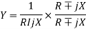
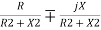


 Y = G
Y = G  jB
jB
|
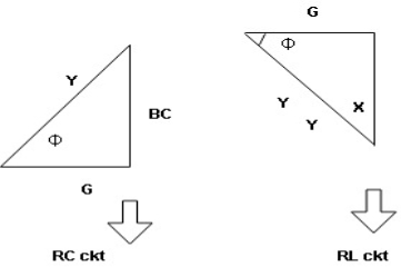
Conductance (G) : it is defined as the ratio of resistance R and the squared impedance (Z2) and it is measured in Siemens or mho 
G = 
Theoretically G = reciprocal od resistance.
Susceptance (B) :it is defined as the ratio of reactance X and the squared impedance (Z2) or mho 
B = 
Theoretically B = reciprocal od resistance.
Reference Books:
- H Cotton, Electrical technology, CBS Publications
- L. S. Bobrow, ―Fundamentals of Electrical Engineering‖, Oxford University Press, 2011.
- E. Hughes, ―Electrical and Electronics Technology‖, Pearson, 2010.
- D. C. Kulshreshtha, ―Basic Electrical Engineering‖, McGraw Hill, 2009.


