Unit 5
Dc Circuit
- Classification based on presence or absence of sources.
- Classification based on the seperability of components.
- Classification based on the linearity
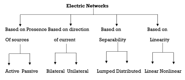
- Active network: If a network consists of an energy source, then it is called as an active n/w. the type of energy source can be voltage source or current source.
- Passive network: If a network does not contain any energy source then it is called the passive network.
- Bilateral or Unilateral Network :
Bilateral network is the network whose characteristics or response does not depend on the direction of current through the various elements in it. Resistive network are bilateral type.
- Unilateral Network :If the characteristics response or behaviour of a n/w is dependent on the direction of current through its elements, then the network is called as Unilateral network. The network containing elements such as diodes, transistors etc. Are Unilateral network.
- Distributed or Lumped network:
Distributed network :If the network elements such as resistances, capacitances, inductances are not physically separable, then it called as a distributed network example of a Distributed network is the transmission line.
- Lumped network :If the network elements can be separated physically from each other, then they are called as lumped network all the simple electric network that we discuss in this unit are lumped network.
- Linear or nonlinear network :If the characterise parameters such as resistance capacitances, inductances etc. remain constant irrespective of change in current, voltage etc. then the circuit or network is called as a linear network 1] eg. Superposition there is applicable only to linear network.
- Nonlinear Network :If the parameters of a network change their value with the change in voltage current etc. then the n/w is called as nonlinear network.
Ideal and practical Voltage and Current source:
A voltage source is a device which provides a constant voltage to load at any instance of time and is independent of the current drawn from it. This type of source is known as an ideal voltage source. Practically, the ideal voltage source cannot be made. It has zero internal resistance. It is denoted by this symbol.
|
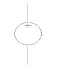
Fig: Voltage source symbol
Ideal Voltage Source
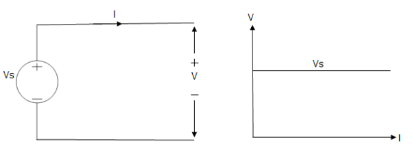
Fig: Ideal Voltage Source
The graph represents the change in voltage of the voltage source with respect to time. It is constant at any instance of time.
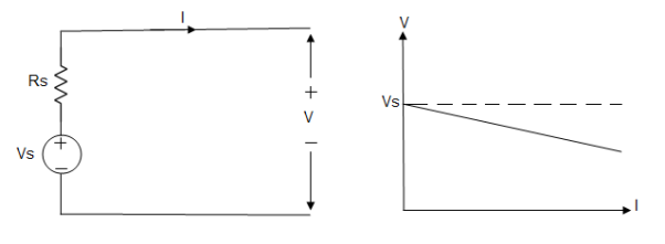
Voltage sources that have some amount of internal resistance are known as a practical voltage source. Due to this internal resistance, voltage drop takes place. If the internal resistance is high, less voltage will be provided to load and if the internal resistance is less, the voltage source will be closer to an ideal voltage source. A practical voltage source is thus denoted by a resistance in series which represents the internal resistance of source.
Practical Voltage source

Fig: Practical Voltage source
The graph represents the voltage of the voltage source with respect to time. It is not constant but it keeps on decreasing as the time passes.
Current source
A current source is a device which provides the constant current to load at any time and is independent of the voltage supplied to the circuit. This type of current is known as an ideal current source; practically ideal current source is also not available. It has infinite resistance. It is denoted by this symbol.
Ideal Current source
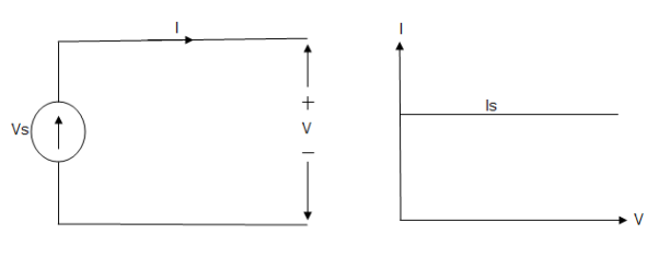
Fig: Ideal Current source
The graph represents the change in current of the current source with respect to time. It is constant at any instance of time.
Why ideal Current source has infinite resistance?
A current source is used to power a load, so that load will turn on. We try to supply 100% of the power to load. For that, we connect some resistance to transfer 100% of power to load because the current always takes the path of least resistance. So, in order for current to go to the path of least resistance, we must connect resistance higher than load. This is why we have the ideal current source to have infinite internal resistance. This infinite resistance will not affect voltage sources in the circuit.
Practical Current source
Practically current sources do not have infinite resistance across there but they have a finite internal resistance. So the current delivered by the practical current source is not constant and it is also dependent somewhat on the voltage across it.
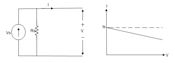
A practical current source is represented as an ideal current source connected with resistance in parallel.
Fig; Practical Current source
The graph represents the current of the current source with respect to time. It is not constant but it also keeps on decreasing as the time passes.
Examples of current and voltage sources
The examples of current source are solar cells, transistors and examples of some voltage sources are batteries and alternators.
This was all about ideal and practical sources of power. The ideal sources are very useful for calculations in theory but as ideal sources are not practically possible, only practical sources are used in practical circuits. The batteries we use are a practical source of power and the voltage and current decreases as we use it. Thus both are useful to us in their own ways.
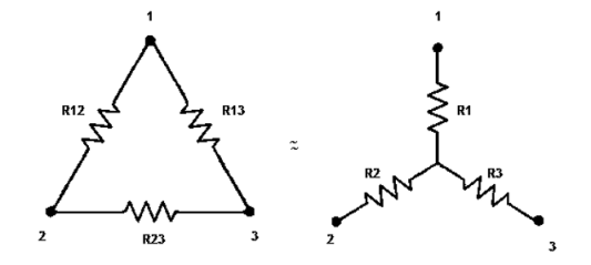
Star to delta conversion to final equivalent resistance
|
We know that (from delta to star conversion) R1 =
R2 =
R1 =
Multiply ① X ② L.H.S and R.H.S
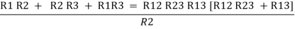
R1 R2 =
Similarly multiply ② X ③
|


R2 R3 =
And ③ X①
R1 R3 =
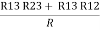
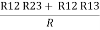
Now add equation ④, ⑤, and ⑥ L.H.S and R.H.S
| ||
(Delta) Similarly R23 = R2+R3 +
| ||


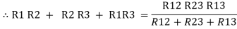


R23 = R1+R2 + 
- Delta to Star Conversion to Find (Req.)
|
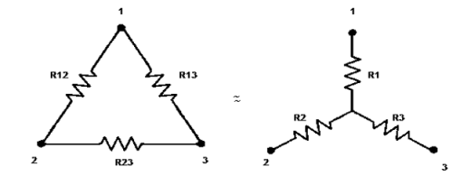
Delta = R12// (R23 + R13) =R1 + R2
=
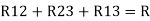
= Here let R = R12 + R23 + R13
=
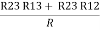
Now the 3 equations after equating L.H.S. and R.H.S R1 + R2 =
R2 + R3 =
R1 + R3 =
|


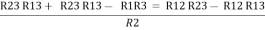
R2+ R3 – R1 – R2 =
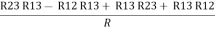
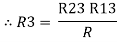
Now add equation ④ and ③
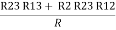
R3 – R1 + R1 + R3 =
2R3 =
Similarly R1 =
| ||
And R2 = R23 R12/R where R = R12 + R23 + R13 ie star equivalent from delta network is ratio of product of adjacent branches in delta to the addition of all branches in delta. | ||


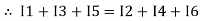
The algebraic sum of currents meeting at a junction or node in a electric circuit is zero ② or the summation of all incoming current is always equal to summation of all outgoing current in an electrical network.
Explanation
|
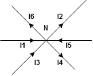
Assuming the incoming current to be positive and outgoing current negative we have
ie |


Kirchhoff’s Voltage Law (KVL)
statement : the algebraic summation of all Voltage in any closed circuit or mesh of loop zero.
ie ∑ Voltage in closed loop = 0 the summation of the Voltage rise (voltage sources) is equal to summation of the voltage drops around a closed loop in 0 circuit for explanation from here
determination of sigh and direction of currents (Don’t write in exams just for understanding)
|
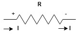
current entering a resistor is +ve and leaving should be –ve
now
|
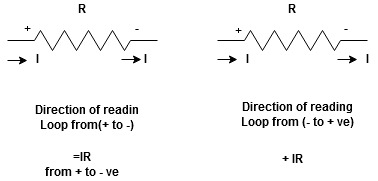


Potential Rise Potential Drop
|
We are reading from +V to –V we are reading from –V to +V
 potential drops
  potential rise
 -V
-V  +V
+V
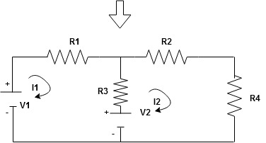
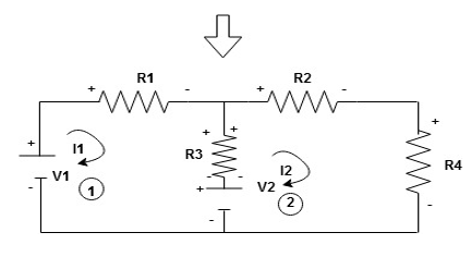
Given Circuit
|
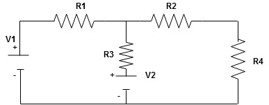
First identify no of loops and assign direction of current flowing in loop
Note : no of loops in circuit = No, of unknown currents = no, of equations in the circuit
|
Note : keep loop direction and current direction same ie either clockwise or anticlockwise for all loops I1 I2
Now according to direction of direction assign signs (+ve to –ve) to the resistors
|
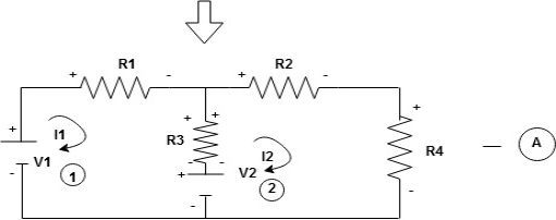
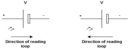
Note : voltage sources (V) polarities does not change is constant.
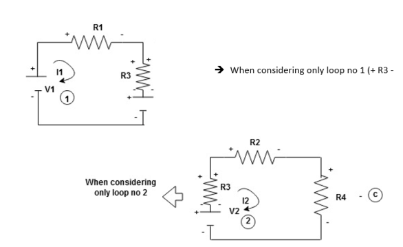
Note: for common resistor between 2 loops appearing in the circuit like R3 give signs according to separate loops as shown
Now consider diagram A and write equations
Two loops  two unknown currents
  two equation
Apply KVL for loop ① [B. Diagram ] (+ to drop -) = - sign and (- to rise +) = + sign
|

- -( |


 )
)
Similarly for loop no. 2 currents flowing is 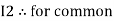 resistor R3 it should be
  )R3
)R3
|
Consider loop no. 1 apply KVL - - Consider loop no. 2 apply KVL - - After solving equation ① and ② we will get branch current |


Statement : the response in any element of linear bilateral network containing more than on sources is the sum of the responses produced by the individual source acting alone. The responses means the voltage across the element or the current in the element The voltage sources should be replaced by short circuit and the current source must be replaced by open circuit .Steps to apply superposition theorem :
1.
|
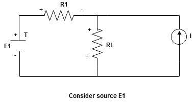
Current sources should be open
|
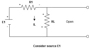
Find the current (IL1)(+) through or the voltage across the required element due to the source under consideration using a suitable n/w technique.
- Consider current source (I) Voltage source should be short circuit
|
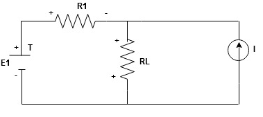
Find the current (ILII)(+) by a suitable network simplification technique
2. Add the individual current IL and ILII by the individual sources acting alone to find total current flowing in load resistance (RL)
ie L =
L = L
L +
+  L
L 
Any network containing active or passive element and or more dependent or independent voltage or current sources can be replaced by an equivalent network containing a voltage source (Thevenins equivalent voltage VTH or VOC) and a series resistance called Thevenins equivalent resistance
|
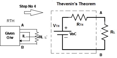
Step to apply Thevenins theorem
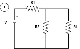
- Remove the branch impedance through which current is required to be calculated
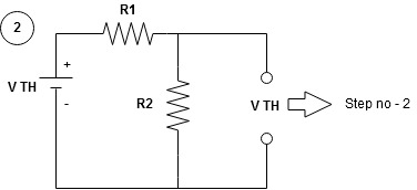
- Calculate the voltage across the open circuit terminals by using and one of the n/w simplification technique. This voltage is Thevenins equivalent voltage VTH.
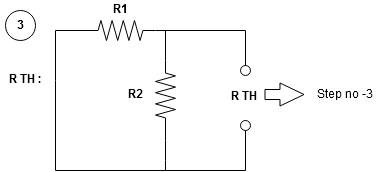
- Calculate the equivalent resistance req. through 2 terminals of the branch from which current is to be calculate by removing load resistance RL and S.C. Vtg. Source and open circuit current source.
- Draw the Thevenins equivalent showing the vtg. Source VTH with RTH or req. in series with it across the terminals of branch through which current is to calculated (Fig A). the required current in branch is given by
 L =
L = 
|
|
Reference Books:
- H Cotton, Electrical technology, CBS Publications
- L. S. Bobrow, ―Fundamentals of Electrical Engineering‖, Oxford University Press, 2011.
- E. Hughes, ―Electrical and Electronics Technology‖, Pearson, 2010.
- D. C. Kulshreshtha, ―Basic Electrical Engineering‖, McGraw Hill, 2009.


