UNIT 6
Development lateral of surface
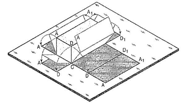
Imagine that a solid is enclosed in a wrapper of thin material, such as paper. If this covering is opened out and laid on a flat plane, the flattened-out paper is the development of the solid. Thus, when surfaces of a solid are laid out on a plane, the figure obtained is called its development.
|
Figure 1
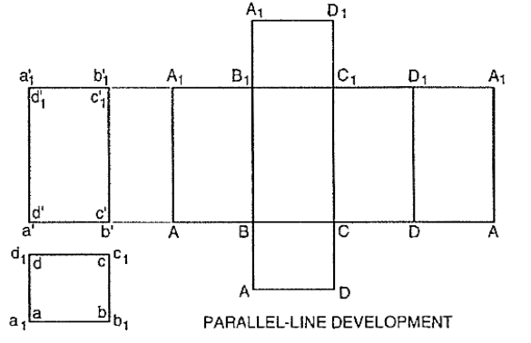
Fig. 1 shows a square prism covered with paper in process of being opened out. Its development (fig. 2) consists of four equal rectangles for the faces and two similar squares for its ends. Each figure shows the true size and shape of the corresponding surface of the prism. The development of a solid, thus represents the actual shape of all its surfaces which, when bent or folded at the edges, would form the solid.
Hence, it is very important to note that every line on the development must be the true length of the corresponding edge on the surface.
The knowledge of development of surfaces is essential in many industries such as automobile, aircraft, ship building, packaging and sheet-metal work. In construction of boilers, bins, process-vessels, hoppers, funnels, chimneys etc., the plates are marked and cut according to the developments which, when folded, form the desired objects. The form of the sheet obtained by laying all the outer surfaces of the solid with suitable allowances for the joints is known as pattern.
Only the surfaces of polyhedra (such as prisms and pyramids) and single curved surfaces (as of cones and cylinders) can be accurately developed. Warped and double-curved surfaces are undevelopable. These can however be approximately developed by dividing them up into many parts.
This chapter deals with the following topics:
1. Methods of development.
2. Developments of lateral surfaces of right solids.
3. Development of transition pieces.
4. Spheres (approximate method).
The following are the principal methodsof development:
1. Parallel-line development:
It is employed in case of prisms and cylinders in which stretch-out-line principle is used. Lines A-A and A1-A1 in fig.2 are called the stretch-out Iines.
2. Radial-line development:
It is used for pyramids and cones in which the true length of the slant edge or the generator is used as radius.
|
Figure 2
3. Triangulation development:
This is used to develop transition pieces. This is simply a method of dividing a surface into many triangles and transferring them into the development.
4. Approximate method:
It is used to develop objects of double curved or warped surfaces as sphere, paraboloid, ellipsoid, hyperboloid and helicoid.
Developments of lateral surfaces of right solids:
The methods of drawing developments of surfaces of various solids are explainedby means of the following typical problems. Only the lateral surfaces of the solids(except the cube) have been developed. The ends or bases have been omitted. Theycan be easily incorporated if required.
The development of the surface of a cube consists of six equal squares, the length of the side of the squares being equal to the length of the edge of the cube.
Problem:
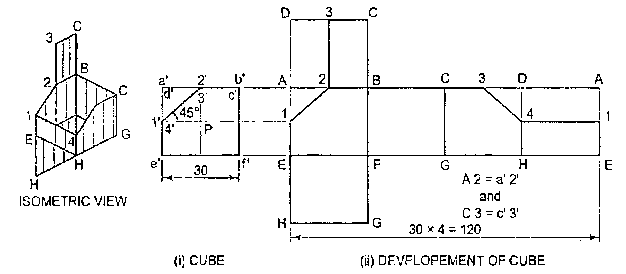
1. Draw the development of the surface of the part P of the cube, the front view of which is shown in fig. 3 (i). Name all the corners of the cube and the points at which the edges are cut.
(i) Draw the stretch-out lines A-A and E-E directly in line with the front view, and assuming the cube to be whole, draw four squares for the vertical faces, one square for the top and another for the bottom as shown in fig. 3(ii).
|
Figure 3
(ii) Name all the corners. Draw a horizontal line through 1' to cut AE at 1 and DH at 4. a' b' is the true length of the edge. Hence, mark a point 2 on AB and 3 on CD such that A 2 = a' 2' and C 3 = c' 3'. Mark the point 3 on CD in the top square also.
(iii) Draw lines 1-2, 2-3, 3-4 and 4-1, and complete the development as shown. Keep lines for the removed portion, viz. A1, A2, 3D, D4 and DA thin and fainter.
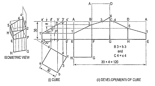
2. Draw the development of the surface of the part P of the cube shown in two views in fig. 4(i).
|
Figure 4
(i) Draw horizontal lines through points 1 ', 2' and 5' to cut AE in 1, BF in 2and DH in 5 respectively. Lines b'c' and c'd' do not show the true lengthsof the edges. The sides of the square in the top view show the true length.Therefore, mark points 3 in BC and 4 in CD such that 83 = b3 and C4 = c4.
(ii) Draw lines joining 1, 2, 3 etc. in correct sequence and complete the requireddevelopment. Keep the lines for the removed part fainter.
Development of the lateral surface of a prism consists of the same number of rectangles in contact as the number of the sides of the base of the prism. One side of the rectangle is equal to the length of the axis and the other side equal to the length of the side of the base.
Problem:
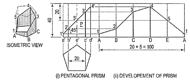
3. Draw the development of the lateral surface of the part P of the pentagonal prism shown in fig. 3 (i).
|
Figure 5
Name the corners of the prism and the points at which the edges are cut.
(i) Draw the development assuming the prism to be whole [fig. 5(ii)].It is made up of five equal rectangles.
(ii) Draw horizontal lines through points 1’, 2’ etc. to cut the lines for the corresponding edges in the development at points 1, 2 etc.
(iii)Draw lines joining these points and complete the development as shown.
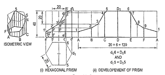
4. Draw the development of the lateral surface of the part P of the hexagonal prism shown in fig. 6 (i).
Name the points at which the edges are cut and draw the development assuming the prism to be whole [fig. 6(ii)].
|
Figure 6
(i) Obtain all the points except 5 and 6 by drawing horizontal lines. Note that points 3 and 8 lie on vertical lines drawn through the mid-points of BC and EF.
(ii) Mark points 5 and 6 such that SD1 = 5d1 and D16 = d16.
(iii) Draw lines joining points 1, 2, 3 etc. in correct sequence and complete the required development as shown.
The development of the lateral surface of a cylinder is a rectangle having one side equal to the circumference of its base-circle and the other equal to its length.
Problem
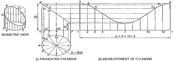
1. Develop the lateral surface of the truncated cylinder shown infig. 7(i).
|
Figure 7
(i) Divide the circle in the top view into twelve equal parts. Project the division points to the front view and draw the generators. Mark points a', b' and b'1, c' and c'1 etc. in which the generators are cut.
(ii) Draw the development of the lateral surface of the whole cylinder along with the generators [fig. 7(ii)]. The length of the line 1-1 is equal to π x D (circumference of the circle). This length can also be marked approximately by stepping off with a bow divider, twelve divisions, each equal to the chord-length ab. (The length thus obtained is about 1 % shorter than the exact length; but this is permitted in drawing work.)
(iii) Draw horizontal lines through points a', b' and b'1 etc. to cut the corresponding generators in points A, B and B1 etc. Draw a smooth curve through the points thus obtained. The figure 1-A-A-1 is the required development.
The development of the lateral surface of a pyramid consists of many equal isosceles triangles in contact. The base and the sides of each triangle are respectively equal to the edge of the base and the slant edge of the pyramid.
Method of drawing the development of the lateral surface of a pyramid:
(i) With any point O as centre and radius equal to the true length of the slantedge of the pyramid, draw an arc of the circle. With radius equal to the truelength of the side of the base, step-off (on this arc) the same number ofdivisions as the number of sides of the base.
(ii) Draw lines joining the division-points with each other in correct sequenceand with the centre for the arc. The figure thus formed (excluding thearc) is the development of the lateral surface of the pyramid.
Problem:
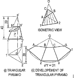
1. Draw the development of the lateral surface of the part P of the triangular pyramid shown in fig. 8 (i). The line o'1' in the front view is the true length of the slant edge because it is parallel to xy in the lop view. The true length of the side of the base is seen in the top view.
(i) Draw the development of the lateral surface of the whole pyramid [fig. 8(ii)] as explained above. On 01 mark a point A such that OA = o'a'. o'2' (with which o'3' coincides) is not the true length of the slant edge.
(ii) Hence, through b', draw a line parallel to the base and cutting o' a' at b". o'b" is the true length of o'b' as well as o'c'. Mark a point B in 02 and C in 03 such that OB = OC = o'b".
(iii) Draw lines AB, BC and CA and complete the required development as shown. Keep the arc and the lines for the removed part fainter.
|
Figure 8
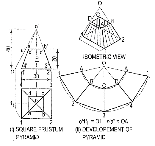
2. Draw the development of the lateral surface of the frustum of the square pyramid shown in fig. 9 (i).
(i) Determine the position of the apex. None of the lines in the front view shows the true length of the slant edge. Therefore, draw the top view and make any one line (for the slant edge) horizontal, i.e. parallel to xy and determine the true length o'1 '1. Through a', draw a line parallel to the base and obtain the true length o'a".
(ii) With O as centre and radius o'1 '1, draw an arc and obtain the development of the lateral surface of the whole pyramid [fig. 9(ii)].
(iii) With centre O and radius o' a", draw an arc cutting O1, O2 etc. at points A, B etc. respectively.
(iv) Draw lines AB, BC, CD and DA and complete the required development. Note that these lines are respectively parallel to lines 1-2, 2-3 etc.
|
Figure 9
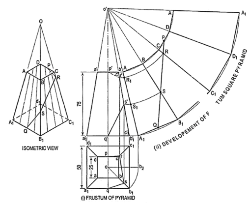
3.A frustum of a square pyramid has its base 50 mm side; top 25 mm side and height 75 mm. Draw the development of its lateral surface.
|
Figure 10
(i) Mark the mid-point P of CD and Q of A1B1. Draw a line joining P and Q and cutting CC1 at R and BB1 at S. Transfer these points to the front view and the top view. For example, with o' as centre and radius o'R, draw an arc cutting o' A1 at R1. Through R1, draw a line parallel to the base and cutting c'c'1 at r'. Project r' to r on cc1 in the top view. r' and r are the projections of R.
(ii) Similarly, obtain s' and s on b'b'1 and bb1 respectively. Draw lines pr, rs and sq which will show the top view of the line PQ. p'r's'q' will be the path of the line PQ in the front view.
The development of the curved surface of a cone is a sector of a circle, the radiusand the length of the arc of which are respectively equal to the slant height andthe circumference of the base-circle of the cone.
Problem:
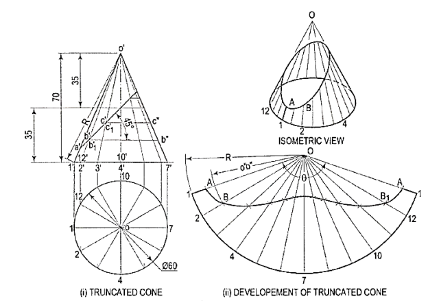
1. Draw the development of the lateral surface of the truncated cone shown in fig. 11 (i).
|
Figure 11
Assuming the cone to be whole, let us draw its development.
(i) Draw the base-circle in the top view and divide it into twelve equal parts.
(ii) With any point O as centre and radius equal to o'1' or o'7', draw an arc of the circle [fig. 15-24(ii)]. The length of this arc should be equal to the circumference of the base circle. This can be determined in two ways.
(iii) Calculate the subtended angle θ by the formula,

Cut-off the arc so that it subtends the angle θ at the center and divide it into twelve equal parts.
(iv) Step-off with a bow-divider, twelve equal divisions on the arc, each equal to one of the divisions of the base-circle.
(This will give an approximate length of the circumference. Note that the base-circle should not be divided into less than twelve equal parts.)
(v) Join the division-points with 0, thus completing the development of the whole cone with twelve generators shown in it [fig. ,11(ii)].
(vi) The truncated portion of the cone may be deducted from this development by marking the positions of points at which generators are cut and then drawing a curve through them. For example, generators o'2' and o'12' in the front view are cut at points b' and b'1 which coincide with each other. The true length of o' b' may be obtained by drawing a line through b', parallel to the base and cutting o'7' at b". Then o'b" is the true length of o'b'.
(vii) Mark points B and 81 on generators 02 and 0-12 respectively, such that OB = 0B1 = o' b". Locate all points in the same way and draw a smooth curve through them. The figure enclosed this curve and the arc is the development of the truncated cone.
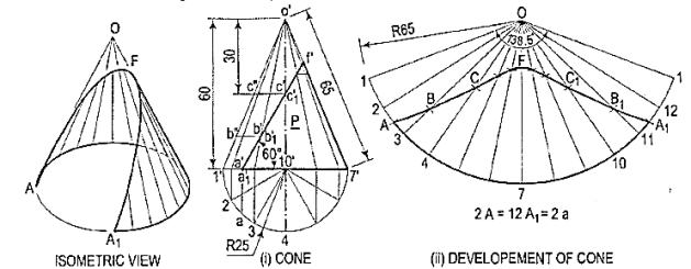
2. Draw the development of the lateral surface of the part P ofthe cone shown in fig. 12
|
Figure 12
Draw the development as explained in problem [fig. 12 (ii)]. For thepoints at which the base of the cone is cut, mark points A and A1 on the arcs2-3 and 11-12 respectively, such that A2 = A1 12 = a2. Draw the curve passingthrough the points A, B, C etc. The figure enclosed between this curve and the arcA-A1 is the required development.
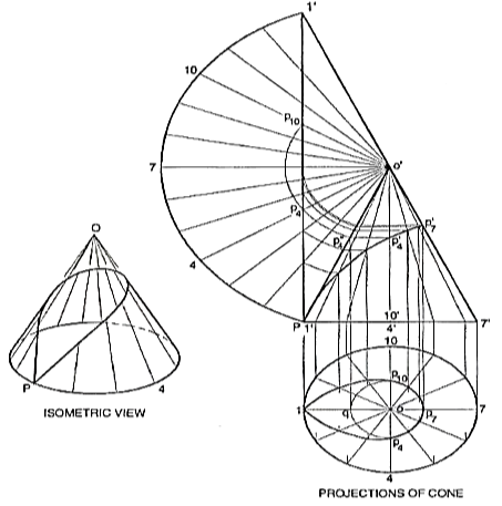
3. Draw the projections of a cone resting on the ground on itsbase and show on them, the shortest path by which a point P, starting from a pointon the circumference of the base and moving around the cone will return to thesame point. Base of cone 61 mm diameter; axis 75 mm long.
|
Figure 13
(i) Draw the projections and the development of the surface of the coneshowing all twelve generators (fig. 13). The development may be drawnattached to o'1 '.
(ii) Assume that P starts from the point 1 (i.e. point 1' in the front view).Draw a straight line 1 '1' on the development. This line shows the requiredshortest path.Let us take a point P4 at which the path cuts the generator o’4. Mark a point P"4 on o'1' such that o'P"4 = o'P4. This can be doneby drawing an arc with o' as centre and radius equal to o'P 4 cutting o11'at P"4. Through P"4, draw a line parallel to the base cutting o'4' at P'4.Then p'4 is the position of the point p4 in the front view.Similarly, transfer all the points to the front view and draw therequiredcurve through them. The curve at the back will coincide with the frontcurve.
(iii) Project these points to the top view on the respective generators. p'4 andp'10 cannot be projected directly. Hence, project p"4 to a point q on o1.With o as centre and radius equal to oq, draw an arc cutting o4 at p4 ando-10 at p10. Thus op4 = op10 = oq. A curve drawn through the pointsthus obtained will show the path in the top view.
Pipes are used in many industries to convey hot or cold fluids. When two different sizes and shapes of pipes are joined using special pipe joint which is known as transition piece. In most cases, transition pieces are composed of plane surfaces and conical surfaces, the latter being developed by triangulation.
Problem:
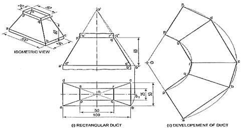
1. In air-conditioning system a rectangular duct of 100 mm x 50 mm connects another rectangular duct of 50 mm x 25 mm through the transition piece as shown in fig. 14(i). Neglecting thickness of a metal sheet, develop the lateral surface of the transition piece as shown in fig. 14(ii).
|
Figure 14
The transition piece is a frustum of a rectangular pyramid.
(i) Determine the position of the apex of the pyramid by extending a'p' and b'q' as shown. None of the lines in the front view shows the true length of the slant edge. Therefore, draw the top view and make any slant line parallel to xy and determine its true length o'b".
(ii) With O as centre and radius o'b", draw an arc and obtain the development of a whole pyramid as shown.
(iii) With Oascentre and radius o'q", draw an arc cutting oa, ob, oc at points p, q, etc. respectively. Join them in sequence and complete the development as shown.
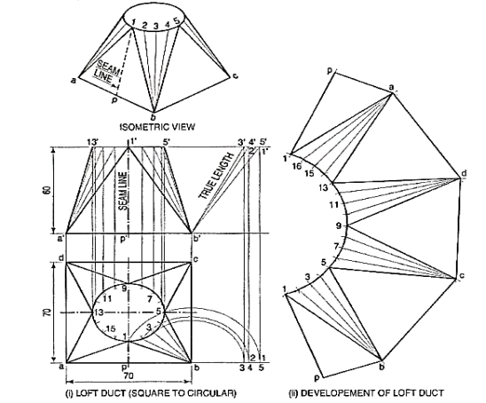
2. An air-conditioning duct of a square cross-section 70 mm x 70 mm connects a circular pipe of 40 mm diameter through the transition piece. Draw the projections and develop the lateral surface of the transition piece.
|
Figure 15
(i) Draw the front view and the top view as shown in fig. 15 (i).
(ii) Divide the top view of circle into some convenient divisions, say 16 parts as shown.
(iii) Note that the transition piece is composed of four isosceles triangles and four conical surfaces. The seam is a long line 1-P.
(iv) Begin the development from the seam line 1-P (1 '-P'). As shown in fig. 15(ii) draw the right-angle triangle 1-P-b, whose base pb is equal to half the side ab and whose hypotenuse 1-b is equal to the true length 1 '-b' of side 1-b.
(v) The conical surfaces are developed by the triangulation method as follows. (vi) In the top view, join division of the circle 1, 2, 3 etc. with the corner a, b, c and d. Project them in the front view as shown. Obtain the true length of sides of each triangle as shown.
(vii) With b as centre and 2'b' (true length) radius draw an arc, cutting the arc drawn with 1' as centre and 1 '2' as radius. Similarly, obtain the points 3', 4', 5' etc. Join them in the proper order as shown.
1. A pipe 40 mm diameter and 120 mm long (along the axis) is welded to thevertical side of a tank. Show the development of the pipe, if it makes anangle of 60° with the side to which it is welded, the other end of the pipemaking an angle of 30° with its own axis. Neglect thickness of the pipe.
2. The inside of a hopper of a floor mill is to be lined with tin sheet. The topand bottom of the hopper are regular pentagons with each side equal to450 mm and 300 mm respectively (internally). The height of the hopper is450 mm. Draw the shape to which the tin sheet is to be cut to fitin the hopper. Scale, 1:10.
References:-
1. Bhatt, N. D. and Panchal, V. M., (2016), “Engineering Drawing”, Charotar Publication, Anand, India
2. K. Venugopal, K, (2015), “Engineering and Graphics”, New Age International, New Delhi
3. Jolhe, D. A., (2015), “Engineering Drawing with introduction to AutoCAD”, Tata McGraw Hill, New Delhi
4. Rathnam, K., (2018), “ A First Course in Engineering Drawing”, Springer Nature Singapore Pte. Ltd., Singapore.
