Unit - 2
Distributed Forces and Friction
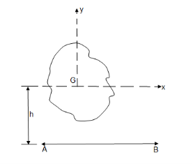
- Gravity axis :
Line of action of the gravitational force acting on the body
- Centre of gravity :
The point through which the whole mass or weight of the body acts, irrespective of its position is known as centre of gravity
- Centre of mass :
The point where the entire mass of a body is supposed to be concentrated
- Centroid : (geometries centre of plane areas )
The plane figures like triangle, quadrilateral, circle have only areas but no mass the centre of area of such figures is known as centroid.
- Procedure to find centroid of composite areas and line :
Select suitable coordinate axes if not given
Divide given area into different parts having known length & area & centroid distanced
If the section is symmetrical about X axis, then we can directly find ȳ axis, then we can directly find X
Let x= x co-ordinate of centre of gravity or distance of C.G. of the area from y axis
y = y co- ordinate of centre of gravity or distance of C.G. of the area from X axis
let a1, a2, a3……… are the areas into which whole figure is divided ,
thenx = 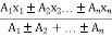
y = 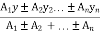
where,
x1, x2, x3 ....... = distances of centroid of part 1,2,3 … from y axis and
x1, x2, x3 ....... = distances of centroid of part x axis
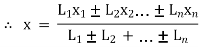
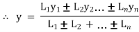
For line segment & wire bents
Replace the area (A) by length (L)
- Problems on the centroid of areas
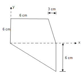
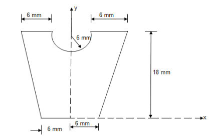
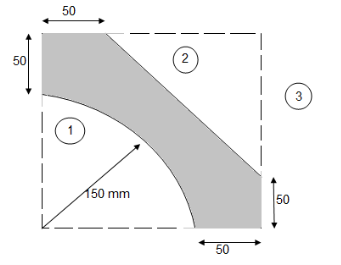
- Locate the centroid of area of the following figure w.r.t. given axis
|
Solution:
|
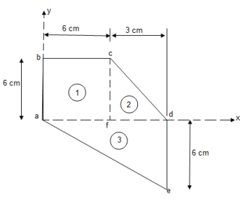
Let us divide the given area as shown above into 3 simple parts.
Consider area ① i.e. Square abcd,
 of □ avcd = A1 =
  = 36 cm2
X1 =  = 3 cm
y1 =  = 3 cm
consider area ② i.e. le cfd,
 A2 = area of
  cfd =
cfd = 

A2 = 9 cm2
X2 = 6 +  = 6 +
= 6 +  = 7 cm
Y2 =  =
=  = 2 cm
Consider area ③ i.e. ade,
ade,
 area of
  ade =
ade = 
A3 = 
A3 = 27 cm2
X3 =  = 6 cm
y3 =  = -2 cm
now
X = 
= 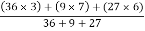
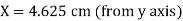
X = 4.625 cm
Y = 
= 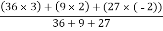
Y = 1 cm
 co-ordinate of centroid of the given area are
Y = 1 cm (from x axis)
2. Determine the Y co-ordinate of the centroid of the shaded area as shown in figure
|
Consider trapezoid as area ① and semicircle as area ②
 For trapezoid and semicircle, shaded area is symmetrical about Y axis and thus as Y axis passing through symmetry line, X = 0
|
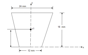
1) For trapezoid :
A1 =  h
h

A1 = 324 mm2
Y1 
Y1 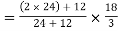 = 10 mm
|
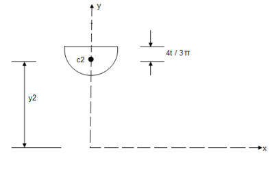
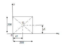
2) For semicircle :
A2 =  = =
= =  = 56.55 mm2
Y2 = 18 -  = 18 -
  = 15.45 mm
Y = =
=  =
=
 y = 8.84 mm
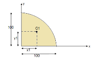
Q. Locate the centroid of shaded lamina as shown in figure
Let us split given composite
Area into simple parts
Area ① - square
Area ② - triangle
Area ③ - quarter circle
|
1.
A1 = 2002 = 40000 mm2
X1 = Y1 =  = 100 mm
|
2.
 A2 =
A2 = 
= 
= 11250 mm2
 X2 = 200 –
X2 = 200 –  = 150 mm
 y2 = 200 –
  = 200 –
  = 150 mm
|
3.
 A3 =
A3 =  =
=  2
2
 A3 = 17671.46 mm2
|
 x3 = y3 =
  =
= 
 x3 = y3 = 63.66 mm
X =  = 107.91 mm
Y =  = 107.91 mm
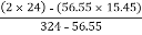
Q: Locate the centroid of shaded lamina as shown in fig.
Consider the composite area
|
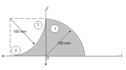
Shown in figure:
Let us split thus composite area into simple parts thus
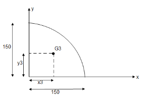
Area ① - quarter circle (shaded)
Area ② - square
Area ③ - quarter circle (non-shaded)
|
- Area ①
A1 =  =
=  2 = 7854 mm2
X1 =  =
=  = 42.44 mm
Y1 =  = 42.44 mm
|
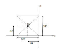
- Area ②
A2 = 100  100 = 10000 mm2
X2 =  = -50 mm
Y2 =  = 50 mm
|
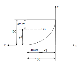
- Area ③
A3 =  =
=  2 = 7854 mm2
X3 =  = 57.56 mm
Y3 =  = 57.56 mm
 Centroid of shaded portion will be
X = 
= 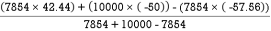
= 
X = 28.54 mm
 Y =
Y = 
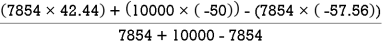
= 
Y= 38.12 mm
Ans:
Centroid of shaded lamina will be at (28.54 mm, 38.12 mm)
|
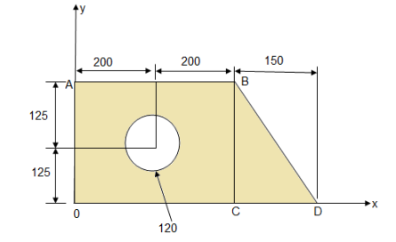
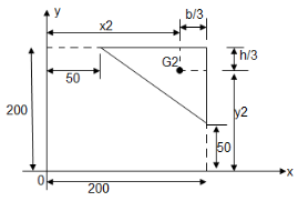
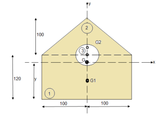
- Determine the X co-ordinate of the centroid of shaded area with respect to origin 0 as shown in figure.
- Consider rectangle O A B C
 area = A1 = 400
  250 = 100000 mm2
X1 = 200 mm
2. Consider right angle  B C D
B C D
 area = A2 =
 mm2
mm2
X2 = 400 + 
= 400 + 
X2 = 450 mm
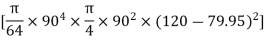
3. Consider circle of  120 mm
Area = A3 = 
A3 =  = 11309.73 mm2
X3 = 200 mm
Thus  X =
X = 
= 
 X = 242.52 mm
|
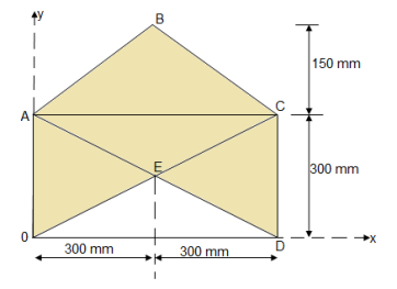
4. Determine the co-ordinate of centroid of the shaded area as shown in figure
The given figure and Shadedarea is Symmetricalabout y axis Shaded area,
X = 300 mm
Let us divide the given diagram into 3 parts
① rectangle O A C D , ②  A B C , ③
  O E D
O E D
|
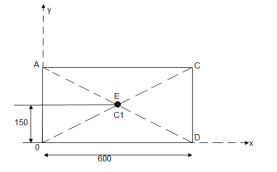
① for rectangle O A C D
A1 = 600 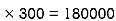 mm2
mm2
Y1 =  = 150 mm
|
② for  A B C
A B C
A2 = 
= 
= 45000 mm2
Y2 = 300 + 
Y2 = 300 + (150/3) = 350 mm
|
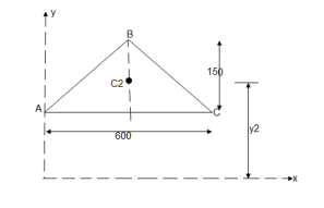
③ For O E D
A3 =  = 45000 mm2
Y3 =  = 150/3 = 50 mm
Y = 
= 
Y = 225 mm
- Determine the y coordinate of centroid of the shaded area as shown in figure:
|
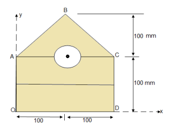
① consider Rectangle O A C D
 A1 = 200
  100 200000 mm2
X1 = 100 mm
Y1 = 50 mm
② consider  A B C
A B C
A2 =  AC
AC  height
=  200
200  100
100
A2 = 10000 mm2
Y2 = 100 +  = 100 +
  = 133.33 mm
③ for circle
A3 =  2 =
2 =  2
2
A3 = 7853.98 mm2
Y3 = 100 mm
 Y =
Y = 
Y = 69.89 m
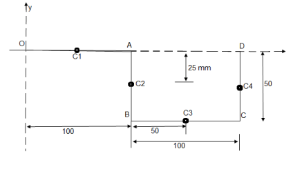
- A thin rod is bent into a shape
 ABCD as shown in figure.
Determine the centroid of bent rod w.r.t. origin ‘O’.
|
|
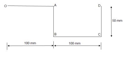
① line segment OA
Length = L1 = 100 mm
X1 = 50 mm co –ordinate of point C
Y1 = 0 mm
② Line segment AB
Length = L2 = 50 mm
X2 = 100 mm
Y2 = -25 mm co-ordinate of C2
③ Line segment BC
L3 = 10 mm
X3 = 150 mm
Y3 = -50 mm co-ordinate of C3
④ Line segment CD
L4 = 50 mm
X4 = 200 mm
Y4 = -25 mm co-ordinate of C4
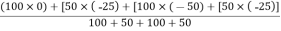
Thus, X =
Y= Y = -25 mm
|


2. A slender rod is welded into the shape as shown in figure
Locate the position of centroid of the rod w.r.t. origin ‘O’ if
AO = BO = CO = 50 mm.
|
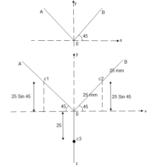
25 cos 45 = 17.68 mm
25 sin 45 = 17.68 mm
Line segment | Length | Centroid | X-coordinate | Y-coordinate |
Line AO | L1 = 50 mm | C1 | X1 = 17.68 mm | Y1 = 17.68 mm |
Line BO | L2 = 50 mm | C2 | X2 = 17.68 mm | Y2 = 17.68 mm |
Line CO | L3 = 50 mm | C3 | X3 = 00 mm | Y3 = -25 mm |
Thus,
X = 
X =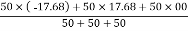
 X = 00 mm from origin ‘O’
Y = 
Y = 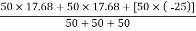
 Y = 3.45 mm from origin ‘O’
Moment of force about any point is the product of magnitude of force and perpendicular distance of line of action of force the point
Mo F  d
d
 O
O
d
F

This is known as first moment of force.
- When this product Mo i.e. (F
 d) is again multiplied with distance ‘d’ then
 2
2
 2 is known as second moment of force or moment of inertia of force.
- When force is replaced by area of figure or mass of the body, then second moment is known as area moment of inertia or mass moment of inertia.
A) Area moment of inertia (I)
The second moment of area about a particular axis is known as area moment of inertia about axis
Unit – mm4, Cm4, m4……
First moment of area = area  distance
= mm2  mm
mm
= mm3
Second moment of area = moment (1st) of area  distance
= area  distance
 distance
= mm3  mm
mm
= mm4
B) Mass Moment of Inertia :
The second moment od mass of the body about a particular axis is known as ‘’mass moment of inertia’’ about thet axis
Unit – kg.mm2, kg.m2

= 
= kg m2
m2
- Radius of Gyration :
If entire mass of body be assumed to be concentrated at a certain point which is located at a distance K from given axis such that
 2
2
 =
= 
Then
Distance K is known as Radius of Gyration
Thus Radius of Gyration is defined as the Distance from the axis of reference where whole mass of the body is assumed to be concentrated
- For plane figure having negligible mass, we can consider area for finding radius of gyration
Thus
 of an area (plane figure)
 2
2
where, Kxx, Kyy, Kzz is radius of gyration of any area ir body about X, y, z, axis respectively | Kxx = Kyy = Kzz = |


- Perpendicular Axis Theorem :
It states that , if  be the moments of inertia of figure or plane section about two axis x and y which are perpendicular to each other at point O, then moment of Inertia of that plane section about Z axis which is perpendicular to the plane [&(
 is given by :
 of plane area about
|
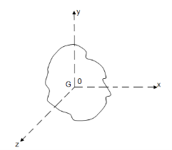
Z axis passing through C.G.
 of plane area about
X axis passing through C.G
 of plane area about
Y axis passing through C.G
 is also called as polar moment of Inertia (J)
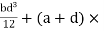
- Parallel axis Theorem:
It states that moment of Inertia of plane area about an axis passing through its centre of gravity is denoted by  G, then moment of Inertia of that area about any other axis AB which is parallel to the first is given by:
 AB =
AB =  G + Ah2

 AB =
AB =  .M. of plane area about axis AB.
 G =
G =  of plane area

it C.G.
A = Area of plane figure
h = distance between centre of gravity of
area & axis AB.
|
- Determine moment of Inertia for
 section about x & y axis as shown in figure.
|
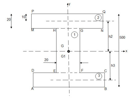
M.I. if this rectangle about xx and yy axis will be,
|
= 106666666.7 mm4 Consider rectangle ABCD area ③
= 213.64
|
|


|
Q: Determine the moment of inertia of shaded area as shown in figure about its centroid as axis.
As this figure is symmetrical about
Y axis
X = 100 mm
Y = 
There ,
area ① = rectangle
area ② = triangle
area ③ = circle
|

Y = 79.95 mm
 to find M.I. of shaded portion , let G is the centroid of shaded area which is at y = 79.95 mm from base.
 of shaded portion @ x-x axis passing through its centroid G will be,
 x-x) +
 x-x) –
 x-x axis)
 1 +
1 +  2
2 3
3
= ( G1 + A1h12) +
  G2 + A2h22) -
  G3 + A3h32)
=  +
+  -60
-60 ] +
] +
 +
+ 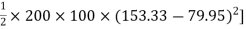 –
–

 84329013.21 mm4
 of shaded portion about y-y axis passing through its centroid G will be,
 y-y) +
 y-y axis) –
 y-yaxis)
 1 +
1 +  2
2 3
3
= 

= 80000000 + 16666666.67 – 3220623.34
 93446043.33 mm4
It is a tangential force developed between the bodies (or two surfaces) which are in contact when one body moves or tends to move over another body (or surface).
Frictional force always acts in the opposite direction of motion or in the opposite direction of impending motion.
- Impending Motion :
It is the state of body in which the body is on the verge of motion i.e. about to move.
Frictional force is denoted by Fs or FK
- Characteristics Frictional Force
- Its reactive and self-adjusting force
- Frictional force increases when external force is increased upto limiting condition.
At the limiting particle try to impend the motion.
When particle is in motion, frictional force decreases with increases in external force.
3. Frictional force always acts in the opposite direction of motion or in the opposite direction of impending motion
4. Upto limiting condition, frictional force is equal in magnitude of external force\.
- Friction
Friction is defined as the resistive force which acts in the opposite direction of motion of body.
- Classification of Friction:
- Static Friction
- Kinetic Friction A) sliding Friction , B) Rolling Friction
- Static Friction :
Friction experienced by a body when it is at rest condition
- Kinetic Friction :
- Friction experienced by a body when it moves
- When one body slides over another, then friction experienced by a body is sliding friction
- When one body rolls over another, then friction experienced by body is called as Rolling Friction.
- Laws of Friction (Coulombs Law)
- For Static Friction :
1) frictional force always acts in opposite direction in which body tends to move
2) frictional force is directly proportional to normal reaction
3) Frictional force is equal to net force acting in the direction in which object
tends to move.
4)Frictional force does not depends an the surface area contanct.
5) Frictional force depends upon roughness of surface.
- For kinetic friction :
1) Frictional force always acts in opposite direction in which body moves
2) Frictional force is directly proportional to normal reaction.
3) For low speeds, frictional force is constant.
4) For higer speeds, frictional force decreases with increasing speed and vice-versa.
- Coefficient of friction :
- Coefficient of static friction (
 ) : from Culombs law
Magnitude of frictional force is directly proportional to normal reaction
 FS
FS RN
RN
 FS =
FS =  S RN
S RN
 S =
S = 
B. Coefficient of kinetic friction ( K) :
K) :
C. FK RN
RN
 FK =
FK =  K RN
K RN
 K =
K = 
|
|


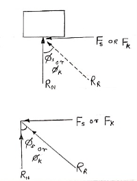
- Angle of Friction (
 ) :
) :
Angle of static Friction ( S) :
S) :
For the body at rest, the angle between
Normal reaction and resultant reaction
Is called as angle of static friction ( S)
S)
 tan (
tan ( S) =
S) = 
 tan
tan  S =
S =  S
S
 S =tan
  Sand
Sand
 S = tan-1
 S
S
- Angle of kinetic friction (
 K) :
K) :
For the body in motion, angle made by normal reaction with resultant is called as angle of kinetic friction ( K)
K)
 tan (
tan ( K) =
K) = 
 tan
tan  K =
K =  K
K
 K =tan
  K and
K and
 K = tan-1
 K
K
- Limiting Friction / Limiting equilibrium :
It is the max value of frictional force when body just begins to slide over a surface.
Or
It is the max value of frictional force when body is just on the verge of sliding.
- Angle of Repose (
 ) :
) :
It is the angle made by inclined surface with the horizontal, when the block kept on inclined plane just begins to slide down the plane due to its self-weight.
|
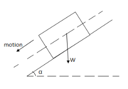
Angle of friction static and angle of repose are equal.
 S =
S = 
 tan
tan  S =
S =  S
S
|
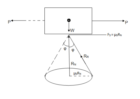
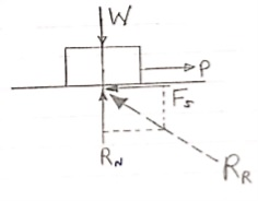
Cone of Friction :
Here
 = semi vertex angle
= angle of friction
In the limiting state of equilibrium, of block , if line of action applied force P is rotated in a horizontal plane, then line of action of resultant reaction RR will also rotate. Due to rotation line of action of RR will generate a cone which is known as cone of friction.
Altitude of Height of Cone = Normal Reaction = RN
Base Radius = Limiting Frictional Force = FS =  SRN
SRN
Generator of Cone = Slant Height = RR = Resultant Reaction.
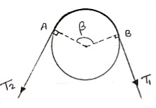
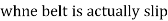
- Belt friction :
- Flat Belt :
|
Let,
T1 Tension in Tight side of belt
T2 Tension in Slack side of belt
 = Lap angle or angle of contact in radians
 S = coeff. Of static friction
 K = coeff. Of kinetic friction
when belt is about to slip :
 =
=  ……… (T1 > T2)
 (in motion) :
 =
=  ……… (T1 > T2)
2. V-Belt
 =
= 
Where  = abgle of V groove or belt
 3. Bond – Brake :
|
|
Q: Determine the horizontal force P needed to just start moving the 300 N crate up the plane as shown in figure. Take  = 0%
= 0%
For the equilibrium
 = 0
= 0
 P – RNcos 70 – FScos 20 = 0
 P – RNcos 70 –
  s FScos 20 = 0
 P – 0.342 RN 0.094 RN = 0
 P = 0.436 RN

 – 300 + RN Sin 70 – FS Sin 20 = 0
 – 300 + RN Sin 70 –
  s FS Sin 20 = 0
 – 300 + RN Sin 70 – 0.1 RN Sin 20 = 0
 – 300 + 0.94 RN – 0.342 RN = 0
 0.9058 RN = 300
 RN = 331.2 N
 n 1
n 1
P = 0.436  331.2
331.2
P = 144.4 N ------------------- force required
|

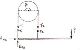
3. Placed
Q: A body of weight 50 N is along rough horizontal plane A pull of 18 N acting at an angle of 140 with the horizontal find coefficient of static friction.
|
Considering the equilibrium of block

 18 Cos 14 – Fs = 0
 Fs = 17.46 N

RN + 18 Sin 14 – 50 = 0
RN = 45.64 N
As Fs =  S RN
S RN
17.46 =  S
S  45.64
45.64
 S = 0.386
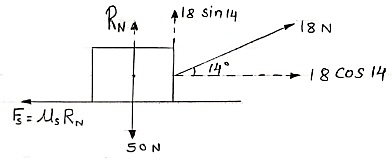
Q: A block of mass m rests on frictional plane which makes an angle  with horizontal as shown if the coeff. Of friction between the block & frictional plane is 0.2, determine angle
  for limiting friction.
|
For limiting friction
Tan  tan
tan  S =
S =  S
S
 tan-1
tan-1 S
S
 tan-1
tan-1
 11.310
Q: Determine whether the block shown is in equilibrium and find the magnitude and direction of friction force when  = 350 and P = 100 N
|
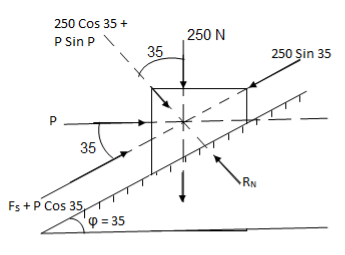
Let us select inclined plane as x-x axis & perpendicular to plane as y-y axis
Let Fs = static frictional force which is required to maintain equilibrium.
 -------- resolving force along x-axis
 Fs + 100 Cos 35 – 250 Sin 35 = 0
 Fs – 61.48 = 0
 Fs = 61.48 N ----- frictional force
 -------- resolving force along y-axis
 -(250 Cos 35 + P Sin 35) + RN = 0
 -250 Cos 35 – 100 Sin 35 + RN = 0
-262.15 + RN = 0
 RN = 262.15 N -------- normal reaction
Maximum frictional force can be developed is given by
Fs max =  S
S RN = 0.3
  262.15
Fs max = 78.65 N
As frictional force required to maintain equilibrium (61.48 N) is less than max. Frictional force,
 Equilibrium will be maintained
Q: 

 At what position from the base, will be induce the slipping of ladder.
Take  S = 0.34 at all contact surface.
Weight of man = 60 9.81 =588.6 N
Weight of ladder 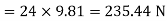
AB = 8 m
|
Impending motion
 Ac = 8 Cos 54
 BC = 8 Sin 54
 ɑ = 2.35 m
 b = x Cos 54
 FSA =
FSA =  S
S  RNA
RNA
 FSB =
FSB =  S
S  RNB
RNB
Considering the equilibrium of ladder
Taking moment about point A,
X = 4.257 m Ans : At X = 4.257 m from point A, along the ladder, man can climb without slipping. Beyond this distance, ladder will be slipping.
|


Q: A 137 kg block is supported by a rope which
Is wrapped 1.5 times around a horizontal
Rod knowing that coeff. Of static friction
Between rope and rod is 0.15, determine
The range of values of P for which
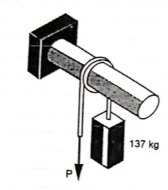 Equilibrium is maintained.
|
Weight of block = 
Angle of contact = LAP Angle
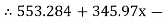
A) Case I : when P > 1343.97 N
Force P tends to move the rope down ward and block moves upward. Thus the part rope on which force P is acting is height side and rope to which block is attached is slack side.
 =
=  =
= 
 P = 5525.34 N
|
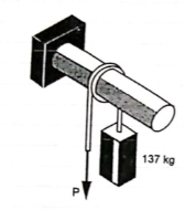
B) Case II : when P < 1343.97 N
 force P is less than 1343.97 N, so block will move down ward & the side rope on which P acts will move upward.
 Rope side to which block is attached is tight side and another side is slack side.
 =
=  =
= 
 P = 326.92 N
 range of P for equilibrium is 326.92 N
Q: Two cylinders are connected by a rope that passes
Over two fixed rods as shown. Knowing that the
Coefficient of static friction between the rope and
The rods is 0.40, determine the range of the mass m
Of cylinder D for which equilibrium is maintained.
Weight of cylinder = 50  9.81 = 490.5 N
Lap angle = 
 S = 0.40
A) Case I :
Weight of cylinder A > weight of cylinder B.
|
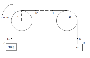
In this case cylinder A will tends to move downward while B will tends to move upward
Consider part AB of the Rope as AB rope is moving down,
tension in hight side T1 = 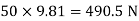
tension in slack side = T2 = unknown.
 =
=  =
=  = 1.874
 = T2
= T2
 T2 = 261.74 N
Consider part CD, of the rope. As rope CD is moving upward,
Tension in tight side T1 = T2 of rope AB
Tension in tight side, T1 = 261.74 N
Tension in slack side = T2 = (m  9.81)
9.81)
|
|


B) Case II :
Weight of cylinder A < weight of cylinder B
|
In this case cylinder a will tends to move upward while cylinder B will tends to move downward
Consider part AB of the rope moving upwards
Tension in slack side = side A = 
|
|


Consider part CD of rope, Rope CD is moving downwards
Tension in tight side = T1 = (m 9.81) N
Tension in slack side = T2 = T1 of rope AB = 919.197 N
|
|


Range of mass m for equilibrium to be maintained is
14.23 kg  m
m 175.59 kg
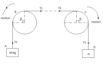
Q: A Force P = mg/6 is required to lower the cylinder with card making 1.25 turns around the fixed shaft. Determine the coeff. Of friction “ S” between the card and the shaft
Refer the figure
Lap angle

= 2.5 radians
|
For flat belt,
 =
= 
 =
= 
 6
6 
 1.79 =
  S
S 2.5
2.5
 S = 0.23
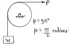
Q: Determine the range of P for the equilibrium of block of weight W as shown in fig. the coeff. Of friction between rope and pulley is 0.2
Case I : when P is max.
 =
= 
 =
= 
 Pmax = 1.369 w
Case II : when P is min.
 =
= 

 Pmin = 0.73 w
For equilibrium P must be between 0.73  P
P  1.369 w
|
Reference Books:
1. Engineering Mechanics by S. P. Timoshenko and D. H. Young, McGraw- Hill publication
2. Engineering Mechanics by J. L. Meriam and Craige, John Willey
3. Engineering Mechanics by F L Singer, Harper and Rowe publication
4. Engineering Mechanics by A. P. Boresi and R. J. Schmidt, Brooks/Cole Publication


