UNIT 4
Analysis of Structures
A two force member is a body that has forces (and only forces, no moments) acting on it in only two locations. In order to have a two force member in static equilibrium, the net force at each location must be equal, opposite, and collinear.
Truss: -
A Rigid structure formed by connecting various two force members to each other by using pin joint.
Plane truss:
When all member of the truss lies in one plane, then truss is known as plane truss
Rigid truss: -
A truss which do not collapse when external Load is applied on it.
Simple truss:-
The structure formed by basic triangle made by Connecting various members are called simple truss
* classification of Truss: -
perfect truss Imperfect (unstable)
(stable) (n  2j R)
2j R)
(n=2j- R) over stable Deficient
Truss .
(Redundant)
(n< 2 j – R) (n < 2 j-R)
- Perfect truss:
A truss which does not collapse under the action of
Load is called perfect truss.
Condition: n = 2 j-R
|
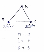
n= no. of member
j = no of joints
R = no. of reaction
In truss ABC, n = 3 & 2 j- R+3
So it is perfect truss
- Imperfect truss: A truss which does not collapse under the load is called
Imperfect or unstable truss.
Here n 2j -R
2j -R
Over stable (Redundant Truss)
A truss in which n > 2j- R,
Then it is over stable truss.
|
Deficient truss
It is a trusses in which
N <2 j-R.
|
- Cantilever Truss:
A truss which is fixed on one side & free of Other end is called as cantilever truss.
.
Diagram
|
*Assumption made in the analysis: -
1) Given truss a perfect truss
2) The truss member is connected by joints only.
3) External loads are acting at the joints only.
4) All members are two force members.
5) The self- weight of members is neglected.
|
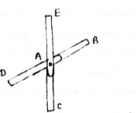
1) If
When four members are connected
At angle joint in such a way
That opposite members lie in a
Single straight line
&
|
there is No external load acting at the joint Then Forces in the opposite members Are equal.
FAE = FAC & FAB = FAD.
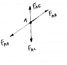
2) If There are only their members at a joint and Out of there, two are collinear and is inclined to first two or lar to first members, With no external load at joint,
|
Then,
a) Forces in the two opposite (co- linear) members
are equal. l.e FAD = FAB
b) The force in the inclined member is zero
l.e FAC =0
c) Force in the perpendicular member is zero
FAc = 0
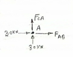
4) If There are two members at a joint with one Member Horizontal & one vertical,
& there is no external load of joint
|
Then, both member is zero force member,
Angle FAB=0
FAC =0
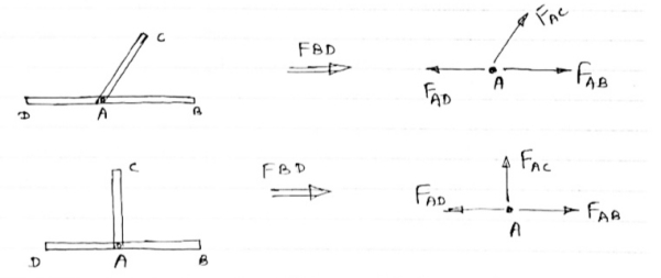
5) If there are only two members at joint With- one-member vertical & other inclined & there is no external load of joint,
|
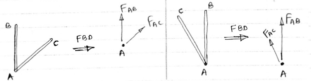
Then Both members are zero force members
i.e FAB = 0 & FAC =0
One-member Horizontal & other inclined and
There is No external load at joint.
|

Then Both members are zero force members
FAB = 0 and FAC =0
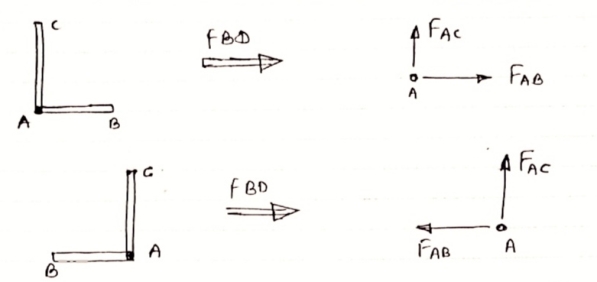
6 ) if there are only two members at a joint with one member Horizontal & other inclined and there is no External load at joint
Diagram
|
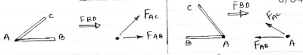
Then both members are zero force member
FAB=0 and FAC = 0
Numerical; -
Analysis of Truss by method of joint method
1)Determine the forces in all members of truss by joint method
|
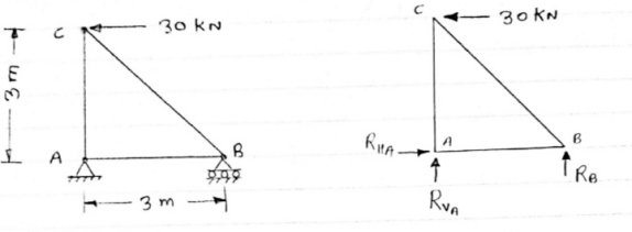
Consider FAB of Truss, Applying conditions of equilibrium,
 = 0
= 0
RHA + 30 Kn
 = 0
= 0
RvA + RB =0
Taking moment at point A, = 0
= 0
-(RB* 3) - (30*3) = 0
RB = -30 KN
RB =30 KN RVA = 30 KN
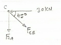
Consider Joint c, assuming forces in member AC & BC to be
Tensile, Applying conditions of equilibrium,
|
 = 0
= 0
-30 + FCB cos 45 =0
FCB =30/cos 45 = 42.42 KN (T)
-  = 0
= 0
- FcA – FCB sin 45=o
|
- F cA -42.42 sin 45 =0
-FCA – 30= 0
-FCA = -30 KN
Consider Joint c, assuming forces in member AC & BC to be
Tensile, Applying conditions of equilibrium,
 Fx = 0 30+FAB =0
FAB = -30KN
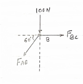
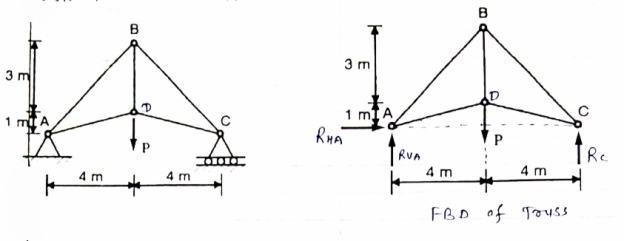
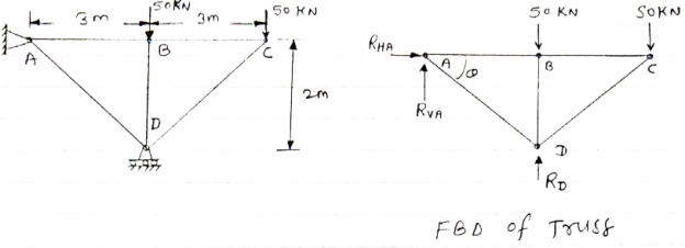
Determine the forces in each member of the plane truss as shown in fig. in terms pf the external loading and state if the members are in tension or compression. Use 0+ 30 deg, L = 2 m and p =100N.
Diagram
|
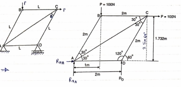
Consider FBD of Truss,
For equilibrium,  Fx =0
Fx =0
RHA+100 =0
RHA =-100 KN
 Fy =0 RVA = RD – 100 ….. 1
MA = 0 -------Taking moment @ A
- (Roxz) + (100*1) + (100*1.732) =0
- - 2 Rd + 100 + 1.7320 =0
- -2 Rd + 100 + 173.2 =0
- RD =136.66 N ()
From eqn (1)
RVA = 100 – 136.6
RVA= 36.6N
RVA = 36.6 N
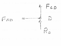
Consider Joint D, for equilibrium,
Fx =0
-FAD + FCD cos 60 =0 – (11)
Fy = 0
|
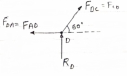
136.6 +FCD sin 60 +0
FCD = -157.73 N ©
From eqn (11), Fad =- 78. 87 N (c)
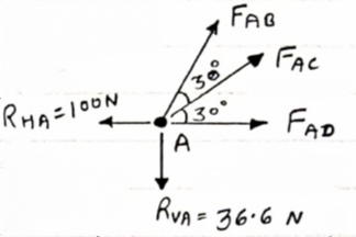
Consider point A, for the equilibrium of point A,
 Fx = 0
- 100 + FAD + FAc cos + 30 FAb cos60 = 0
-100 + (-78.87) +FAC cos 30 +FAb cos60 =0
FAc cos 30 + FAB cos60 + 178. 87 (3)
|
 fx =0
fx =0
-36.6 + FAC sin 30 + FAB sin 60 =0
FAC sin 30 + FAb sin 60 = 36.6
Solving eqn (3) and (4)
FAC = 273.21 N (T)
FAB = -115.47 N
FAB= 115.47 N ©
Consider point B, for the equilibrium of point,
 Fx =0
Fx =0
-FAB cos60 + FBC =0
-[9-115.47) cos60]+ FBC =0
|
FBC = -57.73 N
FBC =57.73N
Member | AB | BC | CD | AD | AC |
force | 115.47N | 57.73N | 157.73N | 78.87N | 273.21N |
Nature | c | c | c | c | T |
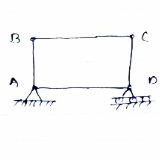
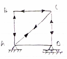
Determine the axial forces in each member of the plane truss as shown in figure.
|
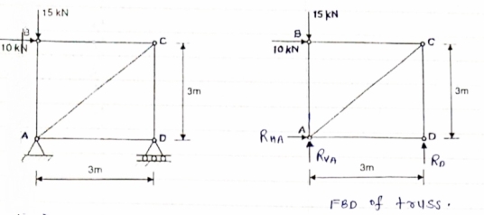
consider FBD of Truss,
For the equilibrium of Truss,  fx =0
fx =0
RHA + 10 =0
RHA = -10 KN
RHA =10KN (
Resolving forces vertically,
 fy =o
fy =o
RVA + RD -15 =0
RVA + RD = 15 …… (1)
Taking moment about point A,
 Fy =0
Fy =0
(10*3) – 3 Rd =0
30+ 3 Rd =0
RD= 10 KN 
RVA = 5KN ( )
)
Now Consider Joint B, FBD of joint B is shown below.
Assuming forces developed in all members to be Termite,
For the equilibrium of joint We have
 fx =0
fx =0
10+FBC =0
|
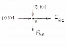
FBC = -10 KN
FBC = 10KN (c)
 fy =0
fy =0
FAB = -15 KN
FAB = 15 KN (c)
Now consider joint c,
For the equilibrium of joint,
 fx =0
fx =0
-FBC – FAC cos 45 =0
- (-10) – FAC cos 45=0
10= FAC cos 45
|
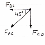
FAC = 10/cos 45
FAc = 14.14 KN (T)
 fy =0
fy =0
-Fac sin 45 – FCD=0
- 14.14 sin45 = FCD
FCD = -10 KN (c)
FCD= 10 KN (c)
Consider joint D,
By observation,
FAD=0
|
Sr .No | Member | Force | Nature |
1 | AB | 15 KN | c |
2 | BC | 10KN | c |
3 | CD | 10KN | c |
4 | DA | 0 | - |
5 | AC | 14.14 | T |
|
Member AB & BC can support a maximum compressive force of 800 N & members AD, DC, BD can support a max. Tensile. Force of 2000N Determine the greatest land p that
|
Consider following geometry of the figure.
|
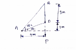
tan 1 = ¼
1 = ¼
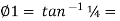 14.04
14.04
 2 =
2 =  =45
=45
 Consider
 fx =0 RHA = 0
∈Fy =o RVA + Rc = p………(1)
∈ma =0
Hp- 8 Rc =0
Rc =P/2 N ( ) RvA = (P/2) N (
 )
)
Consider point A C assuming all forces as Tensile)
∈fx =0
FAD cos 14.04+FAB cos 45 =0… (2)
∈fy = 0 p/2= Fad sin 14.04 + FAB sin 45 =0….. (3)
|
FAB = 2743.9 N > 800 N ( Not Allowed)
Let FAD = 2000 N (T) Then from eqn (2) & (3)
FAB =-274.9 N > 800 ( Not allowed)
Let FAB = .800 N ©, Then put this eqn (2) (3) we get
FAB = 583 N < 2000 N (Allowed) From Eqn (2) P= 848.9 N
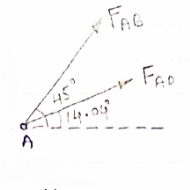
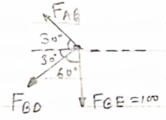
Determine the forces in members 8E and BD of the truss which supports the load as shown in figure.
All interior angle are 60 &120
 Consider joint G
|
∈fx= 0 FGE cos 30- FGF cos 30= 0
FGE cos30= FGF cos 30
FGE=FGF
∈fy=0 FGE sin 30 +FGF sin 30 – 100 =0
FGE sin 30 + FGE sin 30- 100 =0
FGE = 100 N (T)
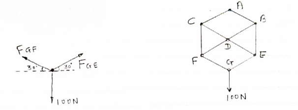
Consider join E
∈ Fx =0
-FDE cos 30 – FGE cos 30 =0
|
-FDE cos 30 – 100 cos 30=0
FDE = -100 N
FDE = 100 N (c)
∈Fy =0
FGE sin 30 + FBE -100 sin 30 =0
(-100) sin 30 = FBE – 100 sin 30
FBE = 100 N (T)
Consider Joint B
 fx = 0 :. – FAB cos30 – FBD cos30 =0
|
:. – FAB –FBD = 0 ……(1)
 fy = 0
FAB sin30- FBD sin 30b - FBE = 0
FAB sin30- FBD sin 30=100
(FAB – FBD)= 200 …………(II)
Solving (1) &(II) FAB = 100N (T)
FBD = 100N
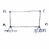
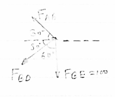
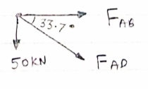
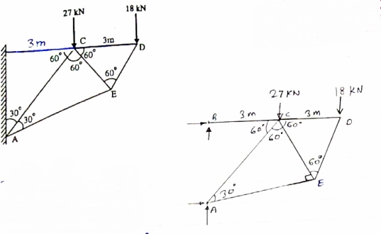
Determine the force in each member of the truss as Shown in fig & tabulate the result with magnitude & nature of force in the members.
Diagram
|
Consider FBD of Truss,
For equilibrium, ∈fx =0
RHA=0
∈fy =0 Zn  ABD
ABD
RVA-50-50+RD =0 tan =2/3
=2/3
RVA + RD =100  = 33.7
Taking moment @ point A,
∈MA =0
-(RD*3) = (50*3) +(50*6) =0
-3Rd = 150 +300 =0
-3Rd = -450
RD = 150 KN (  )
)
RVA= RD = 100
RVA = 150 = 100
RVA= -50
RVA= 50 KN(  )
)
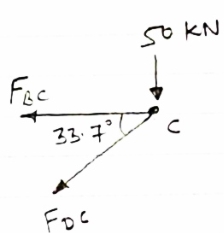
Consider joint A,
|
Diagram
 fx =0,
FAB + FAD cos 33.7 =0
 fy =0
fy =0
-50- FAD sin 33.7 =0
FAD = 50/-sin 33.7 FAD = - 90.1 KN (c)
FAB + (-90.1) cos 33.7 =0 FAB = 74.96 KN (T
Consider joint B
 fx =0
fx =0
-FAB + FBC =0
diagram
|
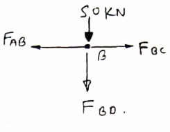
FBC = 74.96 Kn (T)
 fy =0
fy =0
-50-FBD =0
FBD = -50Kn
FBD= 50 Kn
Consider joint c :-
 fx =0
fx =0
-FBC- FDC cos 33.7 =0
Diagram
|
-74.96-FDC cos 33.7 =0
FDC cos 33.7 = -74.96
FDC cos 33.7 = -74.96
DDC = -90.11 KN
FDC = 90.11 KN (c)
Sr No | member | Force | Nature |
1 | AB | 74.96KN | T |
2 | BC | 74.96KN | T |
3 | CD | 90.11 KN | C |
4 | AD | 90.11 KN | C |
5 | BD | 50KN | C |
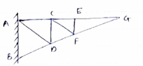
For Given truss find forces in the members BC, AC and AE
Diagram
|
Cantilever Truss
For cantilever Truss, Reaction can be calculated only after the calculated only after the calculation of forces in each member.
Consider joint D, for Equilibrium of joint,
 fx=0
fx=0
-Fcd- FDE cos60 = 0 ……. (1)
|
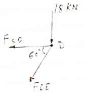
Diagram
 fy =0
fy =0
-18- FDE sin60 = 0
-FDE sin60 = 18
FDE = -20.78 KN
FDE = 20.78 KN
From eqn (1)
-FCD –(-20.78) cos 60 =0
FCD = 20.78 KN
From eqn (1)
-FCD – (20.78)cos 60 =0
FCD = 10.39KN (T)
Consider joint E, for equilibrium of joint,
 fx =0
fx =0
-FCE cos 60- FAE cos30+FDE cos 60 =0
-0.5 FCE -0.866 FAE cos 30 +(-20.78*0.5)=0
|
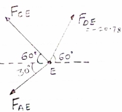
-0.5 FCE-0.866 FAE = 10.39 …..(3)
 Fy =0
Fy =0
(-20.78 sin 60) + FCE sin60- FAE sin 30= 0
0.866 FCE – 0.5 FAE = 17.99 (3)
Solving eqn (2) & (3) FCE= 10.38 KN (T) FAE = -17.99 KN = 17.99 KN (c)
Consider joint C, Equilibrium of the joint
diagram
|
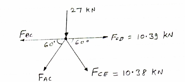
Efx = 0
 - FBC + FCD + FCEcos 60 – FACcos 60 = 0
- FBC + 10.39 + 10.38 cos 60 – FACcos 60 = 0
 - FBC + FACcos 60 = -15.58 ………iv
∑fy = 0
-27 - FAC sin 60 - FCE sin 60 = 0
-27 - FAC sin 60 – 10.38 sin 60 = 0
- FAC sin 60 = 35.99
 - FAC = 41.56 kn
FAC = 41.56 KN
From eqnIV
-FBC – (-41.56cos 60) = -15.58
-FBC = -15.58 – 20.78
-FBC = -36.36 KN
 - FBC = 36.l36 KN …. (T)
Member | BC | AC | AE |
Force | 36.36 KN | 41.56 KN | 17.99 KN |
Nature | T | C | C |
Determine the force in the members of the truss loaded supported as shown the fig. tabulate the result with magnitude and nature of force the members.
|
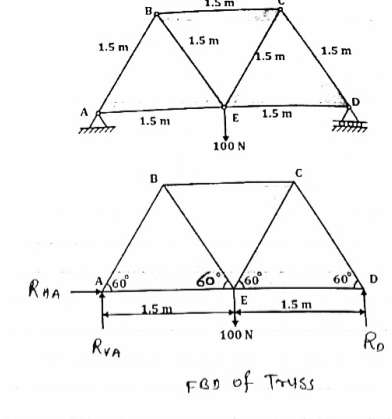
Consider the FBD of truss as show below
For equilibrium of truss
EFx = 0
 RHA = 0
Taking moment @ A
∑MA = 0
 (100
(100  1.5) – (3
  D) = 0
 D = 0
D = 0
 D = 150
 D = 50 N
∑Fy = 0
 RVA
RVA D – 100 = 0
 RVA
RVA – 100 = 0
RVA = 50 N
Consider joint A,
|
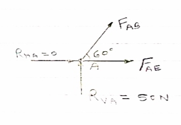
For equilibrium of joint
∑FX = 0
 FABCos60
  AE = 0 ……..①
∑Fy = 0
 RVA
RVA ABSin 60 = 0
 ABSin 60 = 0
FAB = 
FAB = 57.73 N
FAB = 57.73 N ©
From eqn ①
-057.73 Cos 60 + FAE = 0
FAE = 28.86 N (T)
Consider joint B, for the equilibrium of joint
|
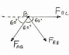
∑FX = 0
 FBC + FBECos60
  ABCos 60 = 0
 FBC + FBECos60
 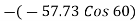 = 0
= 0
 FBC + FBECos60 = 28.86 ②
∑FY = 0
- FAB Sin 60 – FBE Sin 60
-(-57.73 Sin 60) = FBE Sin 60
57.73 Sin 60 = FBE Sin 60
FBE = 57.73 N (T)
From eqn ②
FBC + 57.73 Cos 60 = - 28.86
FBC + 28.86 = - 28.86
FBC = - 57.73 N
FBC = 57.73 N
Consider joint C, for equilibrium of joint
∑FX = 0
 - 57.73 – FCE Cos 60 + FCD Cos 60 = 0
FCE Cos 60 + FCD Cos 60 = 57.73 ……③
∑FY = 0
FCE Sin 60 - FCD Sin 60 = 0 …….④
Solving eqn ③ and④
 FCE = - 57.73 N
 FCE = - 57.73 N and FCD = - 57.73 N (T)
Consider joint D, for equilibrium of joint
|
∑FX = 0
 - FED – FCD Cos 60 = 0
 - FED – 57.73 Cos 60 = 0
- FED = -28.86 N
FED = -28.86 N (T)
Member | AB | BC | CD | DE | AE | BE | CE |
Force | 57.73 N | 57.73 N | 57.73 N | 28.86 N | 28.86 N | 57.73 N | 57.73 N |
Nature | C | C | T | T | T | T | C |
Assumptions in cable Analysis:
- Cables are considered as inextensible
- Self-weight of cable is neglected.
- Loads acting on cables are concatenated (point loads) load.
- Supports are hinged support
- Deflected shape of cables between the two load points is a straight line.
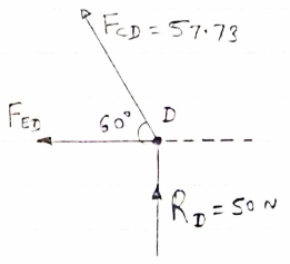
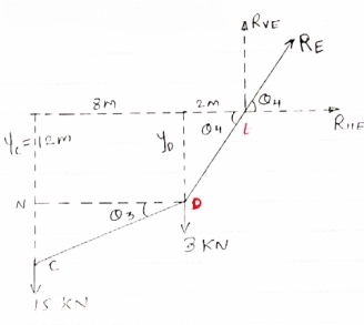
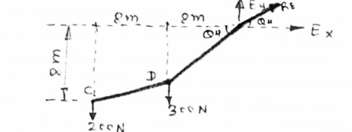
- Determine the tension in segment of cable as shown in figure
|
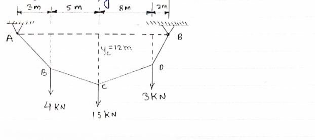
Draw FBD of cable system.
|
For the equilibrium of entire cable system ∑MA = 0
 RVE
RVE 18) = 0
12 + 120 + 48 - 18 RVE = 0
180 = 18 RVE
RVE = 10 KN
Using ∑Fy = 0
 RVA – 4 – 15 – 3 + RVS = 0
RVA + RVE = 22
 RVA = 12 KN
 ∑Fx = 0
RHE – RHA = 0
 RHE = RHA ………..①
- Now as we have taken the moment about point A, let us consider cable system EDC, because the say of point C is known
FBD of cable EDC is shown below
For the equilibrium
∑MC = 0
 taking moment
About point C
|
(3 8) – (RVE
 RHE
RHE = 0
= 0
24 – (10  10) + 12RHE = 0
 12RHE = 76
 RHE = 6.33 KN
From eqn ①
RHA = 6.33 KN
- Now let us find out the angles made by cable with horizontal. i.e
 1 ,
1 ,  2 ,
2 ,  3 ,
3 ,  4 and sag of each point
tan 1 =
1 = =
= 
 1 = tan -1
 = tan-1
 = 62.190
 tan
tan 1 =
1 = 
 tan 62.19 =
  YB = 5.69 m
tan 2 =
2 = =
=  =
=  =
= 
 2 = tan-1
 2 = 51.610
now tan 4 =
4 =  =
= 
 4=
4=  =
= 
 4= tan-1
 = 57.670
  4 = 57.670
 tan 57.67 =
YD = 3.15 m
Also tan  3 =
3 = =
=  =
=  =
= 
 3 = tan-1
 3 = 47.90
- Now let us tension in each segment of cables
 T1 = TAB = RA =
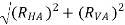
 T1 = TAB = RA =
 T1 = TAB = RA = 13.57 KN
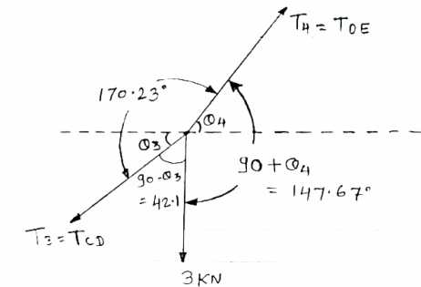
Consider the equilibrium of point C, using lamis theorem,
|
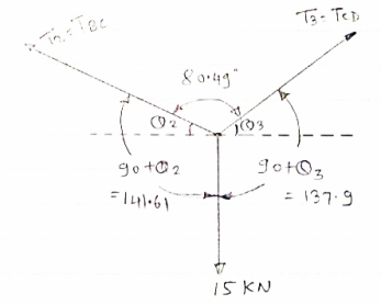
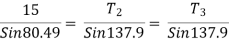

 T2 = 10.2 KN
T3 = 
 T3 = 9.45 KN
consider equilibrium of point D,
|
Using lamis theorem
 T3 =
T3 =  = 9.45
 T3 = 9.45 KN
 T4 =
T4 = 
 T4 = 11.85 KN
 T1 = TAB = 13.57 Kn
 T2 = TBC = 10.2 KN
 T3 = TDC = 9.45 KN
 T4 = TDE = 11.85 KN
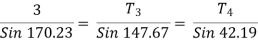
IF YC = 8m determine reaction at A and E and may tension in the cable
|
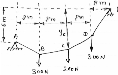
FDB for the cable loaded and supported will be as given below
|
For equilibrium of cable
∑MA = 0
 Y) + (6EX) = 0
 6EX -
6EX -  Y = - 12800 …….①
 ∑FY = 0
  AY + EY – 300 – 200 – 300
 AY + EY = 800 ………②
 ∑FX = 0
  - AX + EX = 0
  EX = AX ………③
As distance of point C is known let us consider cable CDE, FBD will be as below
|
For equilibrium of cable (C D E),
 ∑MC = 0
 (300
(300  EX) – (16 EY) = 0
 8 EX - 16 EY = - 2400 ……….④
 6EX -
6EX -  Y = - 12800 …….①
 8 EX - 16 EY = - 2400 ……….④
Solving ① and ④ simultaneously
 EX = 800 N
EY = 500 N
| Direction of RE
|


From eqn ② and ③
 AY + EY = 800
  AY = 250 N

 AX= EX
 AX = 800 N
 reaction at A, RA =
 RA = 838.15 N
Direction of RA
 1 = tan-1
 1 = 17.350
As EY > AY max tension will occur in cable part DE
 TDE = RE = 970.82 N max tension
Cable ABC supports two Boxes as shown in figure
Knowing that b = 2.7m, find the required
Magnitude of horizontal force P and
Corresponding distance A
|
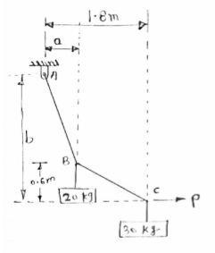
FBD of cable system is given below
|
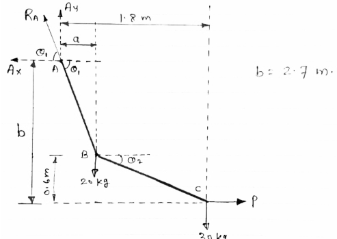
For equilibrium of cable

 ……….①
……….①
∑FY = 0  AY –
AY –  -
-  = 0
= 0
 AY = 490.6 N
∑FX = 0  - AY + P = 0
 AX = P
Now let us consider cable part BC, FBD is shown below
|
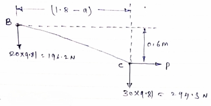
For equilibrium
∑MB = 0


 ……….②
……….②
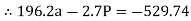
Solving eqn ① and ②
196.2a – 2.7P = - 529.74
294.3a + 0.6P = 529.74
a = 1.22m
P = 284.81 N
- Frames
- Analysis of frames
Frame is a structure which consists of two or more members connected to each other by using pin joint in the frame at least one member is multiforce member.
Frames are stationary structure used to carry the load only.
Unlike the truss, forces can be applied anywhere on the members of frame.
In truss forces are applied at the joint only.
Members of frame are subjected to bending as well as tension and compression.
In the frame force acting on the members may not be collinear with the axis of members.
- Difference between Frame and Truss:
Truss
| Frame
|
Determine the force in member BD of the frame as shown In figure find reaction at C
|
As in this frame there are 2 hinge supports therefore, 4 reactions cannot be calculated. So consider the FBD of each member directly and analyses the frame.
FBD of member’s ABC will be as given below
|
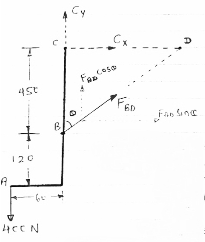
In  BCD
BCD
Cos  =
=  =
= 
 = 28.070
As a members BD is two force members, the force developed in the member BD i.e FBD is considered instead of two reactions at B.
Let FBDis tensile
For equilibrium,
∑MC = 0
 [(FBD Sin
 )
) –(400
–(400 60) = 0
 -(FBD Sin
 - 24000 = 0
-211.75 FBD = 24000
 FBD = - 113.34 N
∑FY = 0
 - 400 + CY +FBD Cos
 = 0
= 0
 - 400 + CY + (-113.34 Cos 28.07) = 0
 CY = 500 N
∑FX = 0
 FBD Sin
 + CX = 0
 (-113.34 Sin
 ) + CX = 0
 CX = 53.33 N
As FBD is negative, our assumption is wrong about the nature of FBD force
Thus FBDis not tensile but it is compressive force

FBD = 113.34 N ( C)
CY = 500 N
CX = 53.33 N
Reaction at C,
RC = 
 RC = 502.84 N
Angle of reaction RC
 = tan-1
 = 83.910
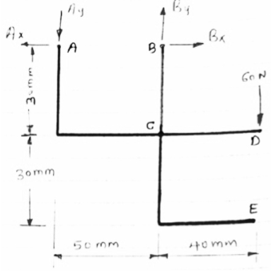
Determine the components of reactions at A and B if 60 N load applied at point D.
|
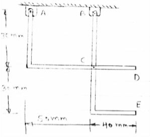
FBD of frame
|
For the equilibrium of entire frame applying conditions of equilibrium.
 ∑MA = 0
 -(50 BY) + (60
  90) = 0
 BY = 180 N
|
|


Now let us separate the frame members and draw FBD of each
members
|
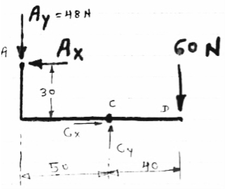
separately
|
FBD of members ACD and BCE are shown above forces acting (reactions) at A,B,C are also shown
Let us apply conditions of equilibrium to members ACD
 ∑MA = 0
 - (AY
- (AY 50) – (AX
 30) + (60
  40) = 0
 - (48
- (48  50) – (30 AX) + 2400 = 0
 - 2400 – 30 AX + 2400 = 0
 AX = 0
 ∑FY = 0
 - AY + CY – 60 = 0
 - 48 + CY– 60 = 0
 CY = 108 N
 ∑FX = 0
 - AX + CX = 0
 CX = 0
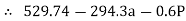
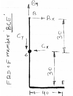
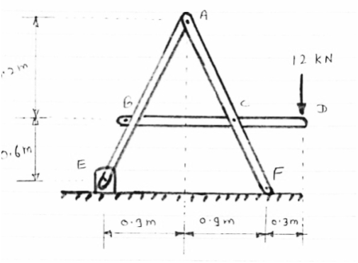
For the frame loaded and supported as shown in figure, determine the components of all forces acting on frame member ABE
|
Consider FBD of the given frame as shown below
|
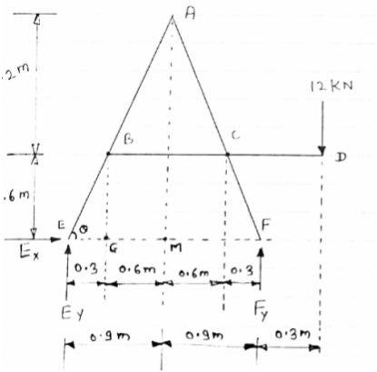
Consider AEm
tan  =
= 

 =63.430
In BEG
tan  =
= 
 EG = 0.3 m
 GM = 0.6 m
For equilibrium of frame,
 ∑ME =0
 - (1.8 FY) + (12
  2.1) = 0
 FY = 14 KN
 ∑FY =0
 EY + FY – 12 = 0
 EY + 14 – 12 = 0
 EY = -2KN = 2 KN
 ∑FX =0
  EY =0
EY =0
|
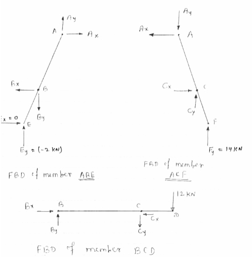
Consider FBD of member BCD,
For equilibrium.
 ∑FY =0
 1.2 CY + (12
  1.8) = 0
 CY = - 18 KN = 18 KN
∑FY =0
 BY – CY -12 = 0
 BY – (-18) – 12 = 0
 BY + 6 = 0
 BY = -6 KN = 6 KN
∑FX =0
 BX – CX = 0
 BX = CX ............①
Now consider FBD of member ABE,
For equilibrium
∑MA =0
 -(BY
-(BY 0.6) + (EY
  0.9) + (BX
  1.2) - (EX
  1.8) = 0
 -0.6 BY + 0.9 EY + 1.2 BX = 0
 -0.6 (-6) + 0.9 (-2) + 1.2 BX = 0
 BX = -1.5 KN
∑FY =0
 EY - BY + AY = 0
 (-2) – (-6) + AY = 0
 -2 + 6 + AY = 0
 AY = -4 KN = 4 KN
∑FX =0
 AX – BX = 0
 AX = -1.5 KN = 1.5 KN
 CX = -1.5 KN = 1.5 KN
- Consider FBD of member ACF
(just for check)
∑FX =0
 - AX + CX = 0
 -(-1.5) + (-1.5) = 0
 0 = 0
0 = 0  CHS = RHS
∑FY =0
 CY – AY + FY = 0
 -18 – (-4) + 14 = 0
 -18 + 18 = 0
0 = 0  LHS = RHS
Thus in member ACF,
∑FX =0
∑FY =0
 It is in equilibrium,
Reference Books
1. Engineering Mechanics by S. P. Timoshenko and D. H. Young, McGraw- Hill publication
2. Engineering Mechanics by J. L. Meriam and Craige, John Willey
3. Engineering Mechanics by F L Singer, Harper and Rowe publication
4. Engineering Mechanics by A. P. Boresi and R. J. Schmidt, Brooks/Cole Publication


