Unit-4
Band-pass Modulation and Demodulation
Digital Modulation provides more information capacity, high data security, quicker system availability with great quality communication. Hence, digital modulation techniques have a greater demand, for their capacity to convey larger amounts of data than analog modulation techniques.
There are many types of digital modulation techniques and also their combinations, depending upon the need. Of them all, we will discuss the prominent ones.
ASK – Amplitude Shift Keying
The amplitude of the resultant output depends upon the input data whether it should be a zero level or a variation of positive and negative, depending upon the carrier frequency.
FSK – Frequency Shift Keying
The frequency of the output signal will be either high or low, depending upon the input data applied.
PSK – Phase Shift Keying
The phase of the output signal gets shifted depending upon the input. These are mainly of two types, namely Binary Phase Shift Keying BPSK and Quadrature Phase Shift Keying QPSK, according to the number of phase shifts. The other one is Differential Phase Shift Keying DPSK which changes the phase according to the previous value.
M-ary Encoding
M-ary Encoding techniques are the methods where more than two bits are made to transmit simultaneously on a single signal. This helps in the reduction of bandwidth.
The types of M-ary techniques are −
M-ary ASK
M-ary FSK
M-ary PSK
Key takeaway
Parameter | ASK | FSK | PSK |
Constant Parameter | Frequency, phase of carrier | Amplitude, phase of carrier | Amplitude, frequency of carrier |
BW | Low | High | Low |
Noise | High | Low | Low |
S/N ratio | Low | High | High |
Data Rate | less | less | high |
ASK
In ASK, the amplitude of the signal is varied to represent the signal levels, while frequency and phase remains constant. In order to represent 0 and 1, two different amplitudes are used.
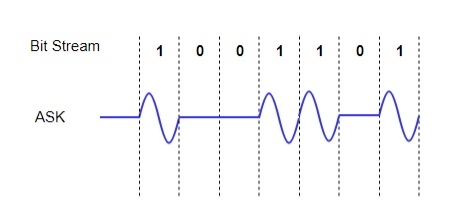
Fig. 1: ASK
PSK
In this, the phase of the carrier signal is modulated to represent the signal levels, while amplitude and frequency remains constant.
Binary Phase Shift Keying (BPSK) is the simplest form of PSK where there are two signal elements represented by two different phases.
In Quadrature PSK (QPSK), two bits of information are transmitted per symbol by using four different phases.
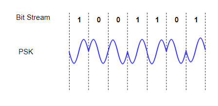
Fig. 2: ASK
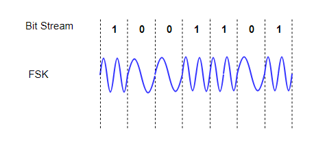
In FSK, the frequency of the signal is modulated to represent the signal levels, while amplitude and phase remains constant.
To represent the signal levels 0 and 1, two different frequencies are used.
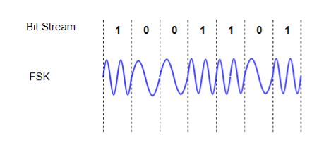
Fig. 3: ASK
Key Takeaways:
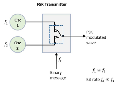
FSK Modulator
The FSK modulator block diagram comprises of two oscillators with a clock and the input binary sequence. Following is its block diagram.

Fig.4: FSK modulator
The two oscillators, producing a higher and a lower frequency signals, are connected to a switch along with an internal clock. To avoid the abrupt phase discontinuities of the output waveform during the transmission of the message, a clock is applied to both the oscillators, internally. The binary input sequence is applied to the transmitter so as to choose the frequencies according to the binary input.
FSK Demodulator
There are different methods for demodulating a FSK wave. The main methods of FSK detection are asynchronous detector and synchronous detector. The synchronous detector is a coherent one, while asynchronous detector is a non-coherent one.
Asynchronous FSK Detector
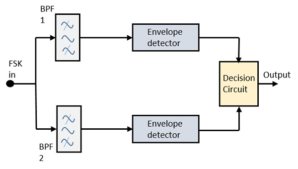
The block diagram of Asynchronous FSK detector consists of two band pass filters, two envelope detectors, and a decision circuit. Following is the diagrammatic representation.
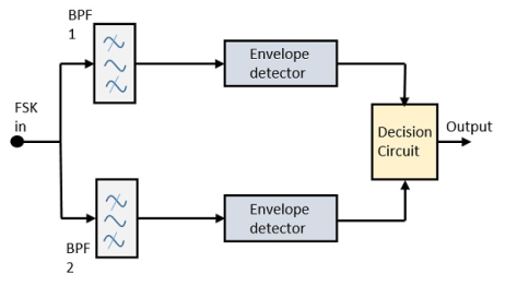
Fig.5 : FSK demodulator
The FSK signal is passed through the two Band Pass Filters BPFs, tuned to Space and Mark frequencies. The output from these two BPFs look like ASK signal, which is given to the envelope detector. The signal in each envelope detector is modulated asynchronously.
The decision circuit chooses which output is more likely and selects it from any one of the envelope detectors. It also re-shapes the waveform to a rectangular one.
GENERATION AND COHERENT DETECTION OF BPSK SIGNALS
(i) Generation
To generate the BPSK signal, we build on the fact that the BPSK signal is a special case of DSB-SC modulation. Specifically, we use a product modulator consisting of two components.
(i) Non-return-to-zero level encoder, whereby the input binary data sequence is encoded in polar form with symbols 1 and 0 represented by the constant-amplitude.
(ii) Product modulator, which multiplies the level encoded binary wave by the sinusoidal carrier of amplitude to produce the BPSK signal. The timing pulses used to generate the level encoded binary wave and the sinusoidal carrier wave are usually, but not necessarily, extracted from a common master clock.
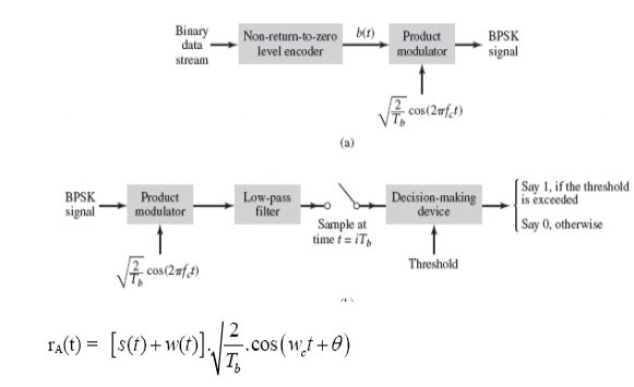
Fig. 6: Generation of BPSK SIgnal
(ii) Detection
To detect the original binary sequence of 1s and 0s, the BPSK signal at the channel output is applied to a receiver that consists of four sections
(a)Product modulator, which is also supplied with a locally generated reference signal that is a replica of the carrier wave
(b)Low-pass filter, designed to remove the double-frequency components of the product modulator output (i.e., the components centered on) and pass the zero-frequency components.
(c)Sampler, which uniformly samples the output of the low-pass filter at where; the local clock governing the operation of the sampler is synchronized with the clock responsible for bit-timing in the transmitter.
(d)Decision-making device, which compares the sampled value of the low-pass filters output to an externally supplied threshold, every seconds. If the threshold is exceeded, the device decides in favour of symbol 1; otherwise, it decides in favour of symbol 0. levels.
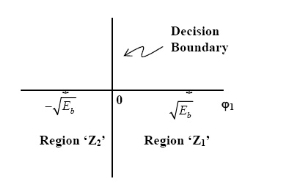
Fig. 7: Decision-making device
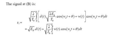
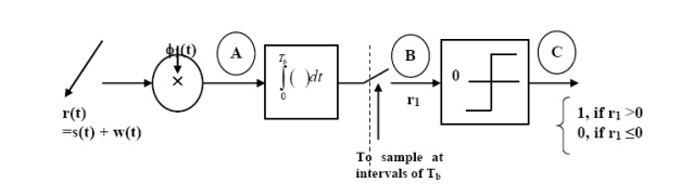
Fig.8: Decision-making device
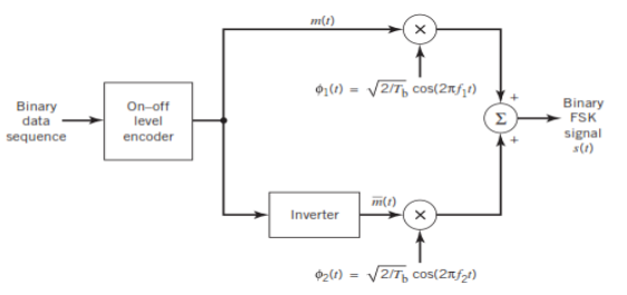
GENERATION AND COHERENT DETECTION OF BFSK SIGNALS
(i) Generation
On-off level encoder:
Here, the output is of constant amplitude √Eb for input 1 and 0 for input 0.
Pair of oscillators:
Frequency f1 and f2 differ by integer multiple of 1/Tb. The lower oscillator has frequency f2 preceded by inverter. When in a signal interval, the input symbol is 1, the upper oscillator is switched on, and signal s1(t) is transmitted, while lower oscillator is switched off.
When input is 0, upper oscillator is off, lower oscillator is on and signal s2(t) is transmitted.
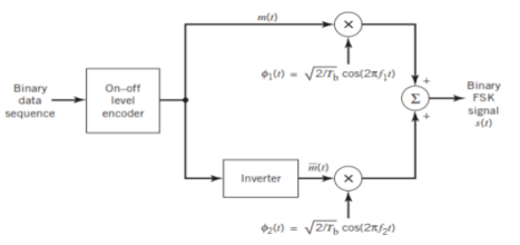
Fig.9: BFSK generation
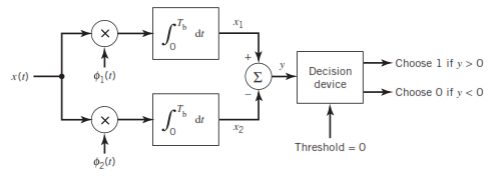
(ii) Detection
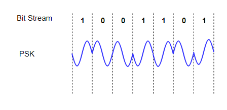
Fig.10: BFSK detection
It consists of two correlators with a common input, and reference signals Ø1(t), Ø2(t) are applied.
Then y = x1 – x2
The output y is compared with the threshold =0
If y>0 then output = 1 else 0.
But if y=0 then the receiver makes a random guess of 0 or 1.
Key Takeaways:
The FSK modulator block diagram comprises of two oscillators with a clock and the input binary sequence
The main methods of FSK detection are asynchronous detector and synchronous detector.
Key Takeaways:
Here, the phase of the modulated signal is shifted relative to the previous signal element. No reference signal is considered here. The signal phase follows the high or low state of the previous element. This DPSK technique doesn’t need a reference oscillator.
GENERATION AND COHERENT DETECTION OF QPSK SIGNALS
(i) Generation
The QPSK Modulator uses a bit-splitter, two multipliers with local oscillator, a 2-bit serial to parallel converter, and a summer circuit.
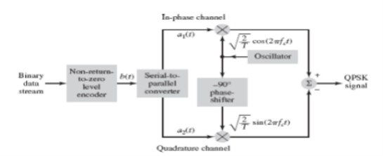
Fig.12: QPSK generation
At the modulator’s input, the message signal’s even bits (i.e., 2nd bit, 4th bit, 6th bit, etc.) and odd bits (i.e., 1st bit, 3rd bit, 5th bit, etc.) are separated by the bits splitter and are multiplied with the same carrier to generate odd BPSK (called as PSKI) and even BPSK (called as PSKQ). The PSKQ signal is anyhow phase shifted by 90° before being modulated.
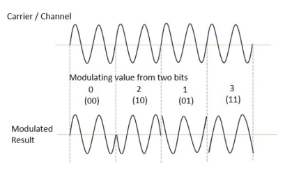
The QPSK waveform for two-bits input is as follows, which shows the modulated result for different instances of binary inputs.
(ii) Detection
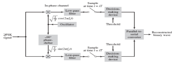
Fig.13: QPSK detectors
The two product detectors at the input of demodulator simultaneously demodulate the two BPSK signals. The pair of bits are recovered here from the original data. These signals after processing are passed to the parallel to serial converter.
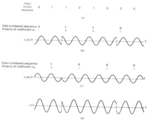
Fig.14: QPSK output
MSK
Minimum Shift Key Modulation is another type of digital modulation technique used to convert a digital signal into analog signals. It is also called Minimum-shift keying (MSK) or Advance Frequency Shift Keying because it is a type of continuous-phase frequency-shift keying.
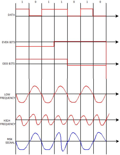
Fig.15: MSK output
Key Takeaways:
The word binary represents two bits. M represents a digit that corresponds to the number of conditions, levels, or combinations possible for a given number of binary variables.
This is the type of digital modulation technique used for data transmission in which instead of one bit, two or more bits are transmitted at a time. As a single signal is used for multiple bit transmission, the channel bandwidth is reduced.
M-ary Equation
If a digital signal is given under four conditions, such as voltage levels, frequencies, phases, and amplitude, then M = 4.
The number of bits necessary to produce a given number of conditions is expressed mathematically as
N=log2M
Where
N is the number of bits necessary
M is the number of conditions, levels, or combinations possible with N bits.
The above equation can be re-arranged as
2N=M
For example, with two bits, 22 = 4 conditions are possible.
This is called as M-ary Phase Shift Keying M−ary PSK
The phase of the carrier signal, takes on M different levels.
Si(t)=√2E/T cos(wot+ϕit) 0≤t≤T and i=1,2...M
ϕi(t)=2πiM where i=1,2,3......M
Some prominent features of M-ary PSK are −
So far, we have discussed different modulation techniques. The output of all these techniques is a binary sequence, represented as 1s and 0s
M-ary FSK
This is called as M-ary Frequency Shift Keying M−aryFSK.
The frequency of the carrier signal, takes on M different levels.
Representation of M-ary FSK
Key takeaway
The transmitted M number of signals are equal in energy and duration.
The signals are separated by 1/2Ts Hz making the signals orthogonal to each other.
Since M signals are orthogonal, there is no crowding in the signal space.
The bandwidth efficiency of M-ary FSK decreases and the power efficiency increases with the increase in M.
It can be seen that the modulating data signal changes the frequency of the signal and there are no phase discontinuities. This arises as a result of the unique factor of MSK that the frequency difference between the logical one and logical zero states is always equal to half the data rate. This can be expressed in terms of the modulation index, and it is always equal to 0.5.
Fig 16 Minimum Shift Keying
MSK is a particularly effective form of modulation where data communications is required. Although QAM and PSK are used for many other systems, MWK is able to provide relatively efficient spectrum usage. As it is a form of frequency modulation, this enables RF power amplifiers to operate in saturation, thereby enabling them to operate as efficiently as possible. If amplitude variations are present these need to be preserved and amplifiers cannot run in saturation and this significantly limits the efficiency levels attainable.
Key takeaway
MSK, minimum shift keying has the feature that there are no phase discontinuities and this significantly reduces the bandwidth needed over other forms of phase and frequency shift keying.
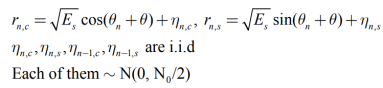
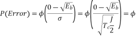
Probability of errors
The analysis for  assumes perfectly white noise j (t) for simplicity. Note that a white noise j(t) has infinite power such that j (t) and c(t)j(t) will have the same PSD

References
1. “Communication Systems”, Simon Haykin, Wiley publication, 4th Edition, 2004
2. “Digital Communication Fundamentals and Applications”, Bernard Sklar, Pearson
Education India, 2nd Edition, 2009
3. “Modern Electronic Communication”, Miller Gary M, Prentice-Hall, 6th Edition, 1999
4. “Digital Communications”, John Proakis, Tata Mc Graw Hill, 5th Edition, 2007
5. “Electronic Communication Systems, Fundamentals Through Advanced”, Wayne Tomsi, Pearson Education, 4th Edition, 2001


