Unit- 5
Canals
A canal is an artificial waterway. The word "canal" origins from the Old French word chanel, which means “channel.” Sometimes it is also known as navigation.
A canal plays a vital role when it comes to transportation and global commerce. We use canal for irrigation, land drainage, urban water supply, hydroelectric power generation.
Canal is a channel usually trapezoidal in section. It is constructed to carry water over long distances from the source of water.
Types of Canals-
We can identify different types of canals based on nature of supply , discharge, branches, provider, alignment, etc.
Based on nature of supply;
1- Permanent canal
2- Inundation canal
Based on discharge there are five types of canals:
- Main canal
- Branch canal
- Major distributary
- Minor distributary
- Watercourse or field channel
Based on lining canals can be classified into two types
- Unlined canals
- Lined canal
Based on alignment there are three canal types:
- Contour canal
- Watershed canal
- Side slope canal
Canals are discussed here-
Permanent canal-When canals are fed regularly or continuously, from a permanent source, such canals are known as permanent canals. Permanent canals have a regular, well defined section. They have permanent concrete masonry regulation works. Such canals run practically throughout the year. Such canals are also sometimes known as Perennial canals. These canals are closed only when either some construction is to be carried out over them or silt clearance is to be done. These canals always take off from ice fed perennial rivers.
Inundation canal-These are such canals which run only for the duration, during which water level in the river remains above some specified level. These canals do not have a very regular section and structures like falls etc. They are not provided with any diversion works in the river, in form of weir or barrage. They however have a head regulator.
Main canal-This canal takes off directly from a river or reservoir. It is generally very big. Being too big, direct irrigation is generally not done from it except in exceptional circumstances. It acts as a carrier to feed branch canals or major distributaries.
Branch canal-Irrigation area for big canals is generally very large. It may not be possible to supply irrigation water from one canal. In such circumstances the main canal is bifurcated into two or more parts, which are known as branch canals. Each branch canal is assigned to the task of irrigating specified area.
Distributaries-Distributaries are channels carrying small discharges of say ½ to 7 cumecs. They usually take off from branch but they can also be taken from main canal, but their discharge has to be smaller than branch canal, otherwise they will become branches. The most of the irrigation is carried out by distributaries. Outlets are located at regular intervals and water is supplied to the fields.
Minors-They are also sometimes called minor distributaries. They take off either from branch or distributaries. Mostly they take off from distributaries. Mostly area lying along the branches is quite high and cannot be irrigated by distributaries. In that case, a small minor is also taken off from the head works of some distributary and this minor is run along the branch canal.
Water courses-They are small channels that ultimately carry water to the fields from outlets. Water courses are also sometimes known as gools. They may be Pucca or lined. Nowadays stress is being given for lining of canals and water courses, as lot of precious irrigation water is otherwise lost in percolation. Outlets are usually taken from distributaries and minors, but they can be taken from branches also but only in special circumstances.
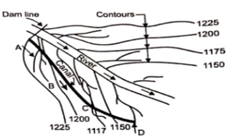
Contour canals-These canals run nearly parallel to the contours of the country. Main canal taking off from a river is hostly contour canal for some length near the diversion head works. Even branch and distributaries can be contour canals. The contour chosen for the alignment should include all the contours of the area it has to irrigate.
Contour canals, provide irrigation on one side only as contours of other side are higher and irrigation water cannot flow under gravity. However irrigation facilities can be provided to the area lying on higher side of the contour canal by lift canals.
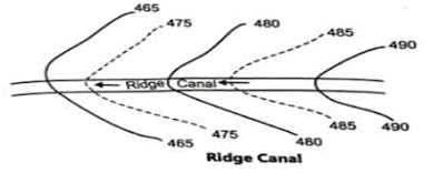
Ridge canal-The canal which follows the ridge of the country is known as ridge canal. It generally takes off from a contour canal. It irrigates on both sides. Since this canal can irrigate areas along both the banks it commands the largest area with minimum length of canal. They do not cross any drainage and hence constructions of cross-drainage works are obviated. If ridge takes a very sharp turn the canal should be aligned straight.
This reduces the length of the canal but envolves construction of cross drainage work to pass run-off from enclosed area, to the other side of the canal. Also irrigation in this enclosed area cannot be done. Canals may also have to leave the watershed to bye-pass the towns and villages located on the water shed. Most of the irrigation canals are ridge canals.
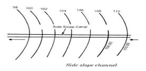
Side slope canal-The side slope channels are aligned roughly at right angles to the contour canals, along the slope between the ridges and the valleys. They are roughly parallel to the natural drainage of the country. They do not intercept any cross-drainage and hence no cross-drainage works have to be constructed. Side slope canals have to be lined, as they have very steep bed slope and Kucha canal may not withstand the erosive effect of increased velocities.
Unlined canals-The canal which runs through the natural soil of the region, is known as Kucha canal or unlined canal. The section of such a canal is trapezoidal. The side slope of the banks depends upon the nature of soil. Slopes vary from 1:1 to 2:1 in cutting and 2:1 to 3:1 in filling for general soils like soft clay, alluvial soil, sandy loan etc.
These canals have to be run with restricted velocity so that erosion or sour may not take place. Large amount of water is lost by percolation. Most of the canals in India are Kucha canals. But government is aware of the shortcomings of such canals and laying more and more emphasis on lining the existing as well as new canals
Lined canal-The section of such a canal in pucca section, made of some strong and impervious material. Lined canals can be run with large velocities and as such section of the canal can be considerably reduced, thus causing economy in the earth work. Lined canals do not allow any percolation loss, and wore ever smaller areas being exposed; evaporation losses are also considerably reduced.
The irrigation water saved by lining of the canals can be used to provide irrigation facilities to additional areas. Lined canals have more bed slope and thus lot of command, is lost as the level of water is depressed faster.
- Head works: The head works are the works constructed to store ,divert and control the river water and regulate the supplies into the canal.
- Main canal : Main canal is staring directly from the upstream side of weir head works.No direct irrigation is usually carried from the main canal.
- Branch canal: When a main canal reaches the area where irrigation is to be done,it divides out into branches joining to different parts of the area.The branch canal ends into a distributary.
- Major distributary or distributary: These are smaller channels takinf-off from the branch canal or sometimes from the main canal.The irrigation water is supplied t the outlets through these distributaries. The capacity of distributary channel may vary from 0.3 to 6 cumecs.
- Minor distributaries or minors: These are small channels of capacity less than 3.3 cumecs taking off from the branch or distributary. The supply water to watercourses for irrigation.Main canals,branch canals and distributaries are called Government channels because they are owned,constructed and maintained by the government.
- Watercourses or fields channels: From these channels,waters enters into th field of cultivators.Watercourses may be constructed by the government on behalf of the cultivators only.These are small channels known as field channels having capacity less than 0.05 cumecs.The length of watercourse is usually less than 1km having a command of 10 to 15 hectares.
Following points should be considered while fixing the alignment of a canal:
1. The canal should be straight. Such a canal would be minimum in length. Length being minimum losses due to percolation and evaporation are bound to be minimum.
2-The canal should follow the ridge as far as possible. This will cause irrigation of the areas lying on both the sides of the canal. If somewhere canal leaves the ridge, our effort should be to catch the ridge again as soon as possible.
3- Cross-drainage works should be minimum, as such works are very costly
4- The canal should not pass through a village or town; but by the side of it.
5- Canal taking off from a river is a contour canal for some length. Every effort should be made to mount if the main water shed, as soon as possible
6- Alignment should avoid deep cuttings and high embankments.
7- the alignment should avoid rock, fissured, and brakish formations. Fissured formations cause loss of water through fissures and brakish formations render water useless. Rocky tracks involve lot of labour for the construction of canals.
8- Suitable foundations for works like falls, cross regulators, head regulators etc. should be available. Besides this, materials of constructions should be available in the vicinity.
9- The canal section should be partly in cutting and partly in filling. Cutting should equal filling if work has to be most economical.
RG Kennedy investigated canals systems for twenty years and come up with a Kennedy’s silt theory. The theory says that, the silt carried by flowing water in a channel is kept in suspension by the eddy current rising to the surface.
The vertical component of the eddy current tries to move sediment up whereas sediment weight tries to bring it down. Therefore, if adequate velocity available to create eddies so as to keep the sediment just in suspension silting will be prevented.
Assumptions regarding Kennedy’s Silt Theory
- The eddy current is generated because of friction between flowing water and the roughness of the canal bed.
- The quality of the suspended silt is proportional to bed width.
- The theory is applicable to those channels which are flowing through the bed consisting of sandy silt or same grade of silt.
Procedure of Canal design using Kennedy’s Silt Theory
There are two cases of canal design using Kennedy’s Silt Theory dependent on the given data. Both cases presented below:
Case 1
The following data shall be available before hand:
Discharge (Q), rugosity coefficient (N), Critical velocity ratio (m) and bed slope of the channel (s).
1. Assume suitable full supply depth (D).
2. Then, find the mean velocity by using Kennedy’s equation (Equation 3
3. After that, find the area of cross section by using continuity equation:
Where:
Q: Discharge
A: cross section area
V: mean velocity computed in step 2
4. Assume the shape of channel section with side slopes (0. 5V:1H)
5. Find out the value of base width of channel (B).
6. Then, find the perimeter of the channel (P). Which helps to find out the hydraulic mean depth of channel (R).
Where:
R: hydraulic mean depth
A: canal cross section area
P: perimeter of the section
7. Finally calculate mean velocity by kutter formula-
:
Value of N
Channel lining | N values |
Earth | 0.0225 |
Masonry | 0.02 |
Concrete | 0.013 to 0.018 |
Case 2
When discharge (Q), rugosity coefficient (N), Critical velocity ration (m) and B/D ratio are given.
1. Assume B/D = X
2. By using the Kennedy’s equation find “V” in terms of D.
3. Find the area of cross section of the channel in terms of D2.
4. By using continuity Equation 4, find the value of D. And then Find the base width (B).
5. Find hydraulic mean depth (R) with Equation 5.
6. Finally, find the value of “V” using Equation 3.
7. Substitute the value of V in step 6 in Equation 6 will gives the longitudinal slope of the channel (S). This case will done by trial and error method.
Limitations of Kennedy’s Silt Theory
- Trial and error method used for the canal design using Kennedy’s Silt Theory.
- There is no equation for bed slope assessment, so the equation developed by Kutter used to compute bed slope.
- The ratio of channel width (B) to its depth (D) has no significance in Kennedy’s Silt Theory.
- There is not perfect definition for salt grade and salt charge.
- Complex phenomenon of silt transportation is not fully accounted and only critical velocity ratio (m) concept is considered sufficient.
Lacey stated that a channel may not be in regime condition even if it is flowing with non-scouring and non-silting velocity. Therefore, he distinguished three regime conditions as follows :
- True regime
- Initial Regime
- Final Regime
1. True regime
A channel is said to be in regime condition if it is transporting water and sediment in equilibrium such that there is neither silting nor scouring of the channel. But according to Lacey, the channel should satisfy the following conditions to be in regime condition.
- Canal discharge should be constant.
- The channel should flow through incoherent alluvium soil, which can be scoured as easily as it can be deposited and this sediment should be of the same grade as is transported.
- Silt grade should be constant.
- Silt charge, which is the minimum transported load should be constant.
If the above conditions are satisfied, then the channel is said to be in true regime condition. But this is not possible in actual practice. Hence lacey defined two other conditions which are initial and final regime conditions.
2. Initial Regime
A channel is said to be in initial regime condition when only the bed slope of channel gets affected by silting and scouring and other parameters are independent even in non-silting and non-scouring velocity condition. It may be due to the absence of incoherent alluvium. According to Lacey’s, regime theory is not applicable to initial regime condition.
3. Final Regime
If the channel parameters such as sides, bed slope, depth etc. are changing according to the flow rate and silt grade then it is said to be in final regime condition. The channel shape may vary according to silt grade as shown in the figure below :
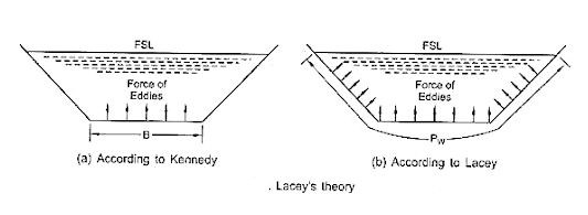
Canal design using Lacey’s Silt Theory
According to lacey’s, the design procedure to build canal is as follows :
- Canal discharge (Q) and mean particle size (dm) should be known.
- From the mean size or diameter of the particle (dm), silt factor is first calculated using the below expression :

- Silt factor values for different types of soils are tabulated here.
S.No | Soil Type | Silt Factor, f |
1 | Fine silt | 0.5 – 0.7 |
2 | Medium silt | 0.85 |
3 | Standard silt | 1 |
4 | Medium sand | 1.25 |
5 | Coarse sand | 1.5 |
- Using discharge and silt factor, velocity (V) can be calculated by the expression as follows :

After attaining the velocity of canal flow, find the area of the canal by dividing discharge with velocity. Also, find the mean hydraulic depth (R) of the canal and wetted perimeter (P) of the canal.
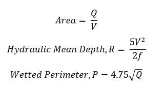
- Assume the bed slope (S) value or find by substituting the values of silt factor and canal discharge in the following formula :

Canal Linings are provided in canals to resist the flow of water through its bed and sides. These can be constructed using different materials such as compacted earth, cement, concrete, plastics, boulders, bricks etc. The main advantage of canal lining is to protect the water from seepage loss.
Canal Lining is an impermeable layer provided for the bed and sides of canal to improve the life and discharge capacity of canal. 60 to 80% of water lost through seepage in an unlined canal can be saved by construction canal lining.
Need Of Canal Lining-
[1] Reduction of seepage losses through unlined canal section thereby making available additional supplies for extension of irrigation to new areas.
[2] Prevention of water-logging in the area adjacent to the canal by reducing seepage of canal water to water table.
[3] Improvement of discharging capacity of existing channel.
[4] Improvement of discharging capacity of existing channel.
[5] Elimination of slitting problems inherent in unlined canals due to higher velocities possible in lined channels.
[6] Reduction in maintenance cost.
[7] Reduction in cost of excavation due to reduced cross section (and thereby saving in land) with increased velocity permissible in lined section.
[8] Increase in available head for power generation as also to command more area as a flatter gradient can be provided in lined channels and
[9] Prevention of weed growth. The necessity of lining has to be established by quantifying the contribution of each of the above factors and assessing the overall economy to be achieved by lining a canal.
REQUIREMENT OF CANAL LINING-
- Reduction in seepage losses
- Low maintenance cost
- Minimizes the possibility of breaching of canals
- Prevents weed growth
- Improved hydraulic efficiency of canals
- Reduces cross sectional dimensions of canal
- Improvement in command.
Types of Canal Linings
Canal linings are classified into two major types based on the nature of surface and they are:
- Earthen type lining( soft surface lining)
- Hard surface lining
1- Soft surface lining- there are two types of lining-
Compacted Earth Lining
Soil Cement Lining
Compacted Earth Lining
Compacted earth linings are preferred for the canals when the earth is available near the site of construction or In-situ. If the earth is not available near the site then it becomes costlier to construct compacted earth lining.
Compaction reduces soil pore sizes by displacing air and water. Reduction in void size increases the density, compressive strength and shear strength of the soil and reduces permeability. This is accompanied by a reduction in volume and settlement of the surface. Proper compaction is essential to increase the stability and frost resistance (where required) and to decrease erosion and seepage losses.
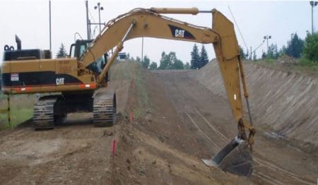
Fig 2: Compacted Earth Lining
Soil-cement linings are constructed with mixtures of sandy soil, cement and water, which harden to a concrete-like material. The cement content should be minimum 2-8% of the soil by volume. However, larger cement contents are also used.
In general, for the construction of soil-cement linings following two methods are used.
- Dry-mix method
- Plastic mix method
For erosion protection and additional strength in large channels, the layer of soil-cement is sometimes covered with coarse soil. It is recommended the soil-cement lining should be protected from the weather for seven days by spreading approximately 50 mm of soil, straw or hessian bags over it and keeping the cover moistened to allow proper curing. Water sprinkling should continue for 28 days following installation.
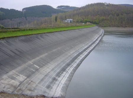
Fig 3: Soil Cement Lining
Hard Surface Canal Linings
It is sub divided into 4 types and they are
- Cement Concrete Lining
- Brick Lining
- Plastic Lining
- Boulder Lining
- Buried lining
- Soil cement lining
Buried lining-
A buried membrane canal lining consists of a relatively thin and impervious water barrier covered by a protective layer which forms the water-carrying prism. The asphalt spray, plastic film, bentonite and prefabricated asphalt are used as construction material for membranes. Since the protective cover does not get properly attached with the plastic sheet, sloughing and slipping of earth on the sides usually take place. The minimum side slope recommended is 2:1.
The life of the lining depends largely on erosion resistance of cover material. Skilled personnels are required; it can be transported easily along the canal. Suitability of excavated soil as cover material is important for economic reasons.
Advantages Of Canal Lining-
- Seepage Reduction
- Prevention of Water Logging
- Increase in Commanded Area
- Increase in Channel Capacity
- Less Maintenance
- Safety Against Floods
DESIGN OF LINED CANALS-
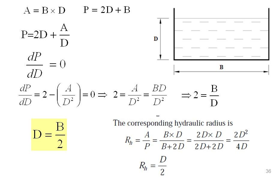
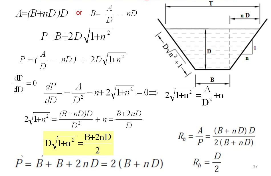
There are 2 popular eqn are used for the design of rigid channel. One is chezy and other is manning.these equations are given below-
Chezy’s equation-
Q = AC√(rS),
Where A is the cross-sectional area of the river, C is the Chezy discharge coefficient, r is the hydraulic radius, and S is the slope of the water surface.
Q=A.V
- Rectangular channel-
2-trapezoidal channel section-
Introduction
Canal fall is a solid masonry structure which is constructed on the canal if the natural ground slope is steeper than the designed channel bed slope. If the difference in slope is smaller, a single fall can be constructed. If it is of higher then falls are constructed at regular suitable intervals.
When the slope of the ground suddenly changes to steeper slope, the permissible bed slope can not be maintained. It requires excessive earthwork in filling to maintain the slope. In such a case falls are provided to avoid excessive earth work in filling When the slope of the ground is more or less uniform and the slope is greater than the permissible bed slope of canal.
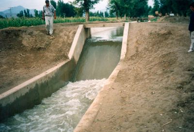
In that case also the canal falls are necessary. In cross-drainage works, when the difference between bed level of canal and that of drainage is small or when the F.S.L of the canal is above the bed level of drainage then the canal fall is necessary to carry the canal water below the stream or drainage.
Selection Of Site For Canal Falls-
- For main and branch canals, which do not directly irrigate the fields, the site is determined on the basis of economy in earth works. The excavated earth is used to make banks. This depth of excavation is known as balancing depth of excavation. Suitable site for canal falls will be where the depth of excavation becomes less than the balancing depth.
- For the Distributory and minor canals, falls may be located downstream of the outlets as this help in increasing the command area, and in improving the efficiency of outlets.
- Site should be selected keeping in mind the requirements for a road crossing, as a bridge combined with a fall offers an economical structure.
- A regulator may be combined with a fall downstream of the off-taking channel. It has been done in Bombanwala head works on upper chenab canal. At this site, BRBD canal and Rayya branch canal take off in Punjab Pakistan
The important types of falls which were used in olden days and those which are being used in modern days are described below:
- Ogee falls
- Rapid falls
- Stepped falls
- Trapezoidal notch falls
- Well type falls
- Simple vertical drop falls
- Straight glacis falls
- Montague type falls
- Inglis falls or baffle falls
1- Ogee Fall
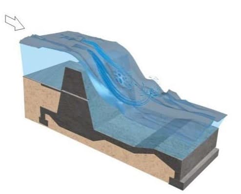
In this type of fall, an ogee curve (a combination of convex curve and concave curve) is provided for carrying the canal water from higher level to lower level. This fall is recommended when the natural ground surface suddenly changes to a steeper slope along the alignment of the canal.
- The fall consists of a concrete vertical wall and concrete bed.
- Over the concrete bed the rubble masonry is provided in the shape of ogee curve.
- The surface of the masonry is finished with rich cement mortar (1:3).
- The upstream and downstream side of the fall is protected by stone pitching with cement grouting.
- The design consideration of the ogee fall depends on the site condition.
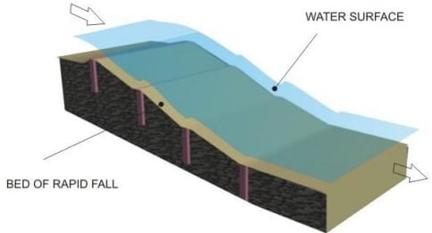
2- Rapid falls-
Rapid fall consists a long sloping glacis. It is constructed if the available natural ground surface is plane and long. For this, a bed of rubble masonry is provided and it is finished with cement mortar of 1:3 ratio. To maintain the slope of bed curtain walls are provided at both upstream and downstream. Rapid falls are high priced constructions.
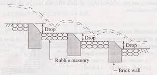
3-Stepped Canal Falls
As in the name itself, stepped fall consist vertical steps at gradual intervals. Stepped fall is the modification of rapid fall. It is suitable for the canal which has it upstream at very high level as compared to downstream. These two levels are connected by providing vertical steps or drops as shown in figure.
4-Trapezoidal Notch Canal Falls
In case of trapezoidal notch falls, a high crested wall is built across the channel and trapezoidal notches are provided in that wall. Trapezoidal falls are very economical and suitable for low discharges. Now a days this type of falls are using widely because of their simplicity and popularity.
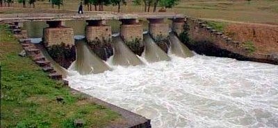
5-Simple Vertical Drop Falls (Sarda Type fall)
Simple vertical drop fall or sarda fall consists, single vertical drop which allows the upstream water to fall with sudden impact on downstream. The downstream acts like cushion for the upstream water and dissipate extra energy. This type of fall is tried in Sarda Canal UP (India) and therefore, it is also called Sarda Fall.
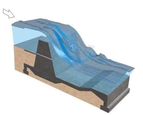
6-Straight Glacis Canal Falls
This is the modern type of construction, in which a raised crest is constructed across the canal and a gentle straight inclined surface is provided from raised crest to the downstream. The water coming from upstream crosses the raised crest and falls on inclined surface with sufficient energy dissipation.
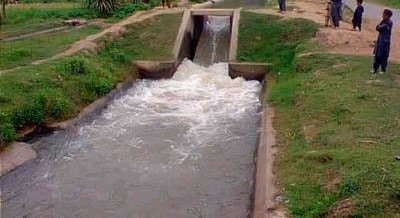
7-English or Baffle Canal Falls

In this case, straight glacis fall is extended as baffle platform with baffle wall. This is suitable for any discharge. The baffle wall is constructed near the toe of the straight glacis at required distance in designed height. The main purpose of the baffle wall is to create hydraulic jump from straight glacis to baffle platform.
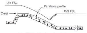
8- Montague Type Canal Falls
Montage fall is similar to straight glacis fall but in this case the glacis is not straight. It is provided in parabolic shape to introduce the vertical component of velocity which improves the energy dissipation to more extent.
This type of a fall consists of an inlet well with a pipe at its bottom, carrying water from the inlet well to downstream well or a cistern.
Well type falls are also called as syphon drop falls. In this case, an inlet well with pipe at its bottom is constructed in upstream. The pipe carries the water to downstream well or reservoir. If the discharge capacity is more than 0.29 cumecs then downstream well is preferred otherwise reservoir is suitable.
This type of .falls are very useful for affecting larger drops for smaller discharges. They are commonly used as tail escapes for small canals, or where high levelled smaller drains do outfall into a low levelled bigger drain.

Simple vertical drop fall or sarda fall consists, single vertical drop which allows the upstream water to fall with sudden impact on downstream. The downstream acts like cushion for the upstream water and dissipate extra energy. This type of fall is tried in Sarda Canal UP (India) and therefore, it is also called Sarda Fall.
The main considerations in selection of a type of fall are:
(i) The height of drop, and
(ii) The discharge passing over the fall. In other words the amount of energy to be dissipated dictates the type. The type which dissipates energy most satisfactorily should be selected.
When full energy dissipation does not take place on the masonry structure of the fall, the issuing jet still possesses higher velocities than what the soil can withstand. In these circumstances provision of baffle becomes obligatory.
Where the bed material is hard enough to withstand scouring action of the strong current, the type of fall that envisages dissipation of just surplus energy could be adopted. For un-flumed conditions the baffle design is well suited under clear over fall conditions especially where the soil is easily erodible.
For flumed conditions vertical type is not suitable because effective dissipation is difficult and harmful scouring is always expected. In such cases the glacis fall either with straight sloping floor or with baffle wall may prove useful.
In drowned fall conditions fall structure with a baffle may not be necessary and straight glacis with 3 to 4 rows of friction blocks and a deflector may be adopted for a flumed condition and a vertical fall for un-flumed condition may be adopted. For canals with discharges below 8 cumec the choice may be based on cost consideration alone.
Canal outlet is a device through which water is released from a distributing channel into a water course. ... Module outlets: The discharge through modular outlets is independent of the water levels in the distributing channel and the watercourse, within reasonable working limits.
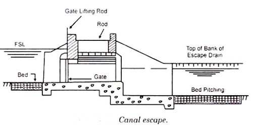
A canal escapes is a structure constructed on an irrigation canal for the disposal of surplus water from the canal Structures meant to release excess water from a canal, which could be main canal, branch canal, distributary, minors etc.
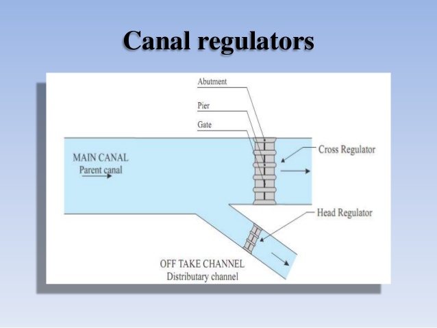
Structure at the head of canal taking off from a reservoir may consist of number of spans separated by piers and operated by gates. Regulators are normally aligned at 90° to the weir. Up to 10" are considered preferable for smooth entry into canal. The functions of canal head regulator are:
- To admit water into the off taking canal.
- To regulate the supplies into the canal.
- To indicate the discharge passed into the canal from design discharge formula and observed head of water on the crest.
- To control the silt entry into the canal. During heavy floods, it should be closed otherwise high silt quantity will leave to the canal.
Reference Books
- Design of Small Dams- United States Department of the Interior, Bureau of Reclamation revised reprint 1974, Oxford and IBH Publishing Co.
- Irrigation and Water Resources Engineering- Asawa G.L- New Age International (P) Ltd. Publishers, first ed, 2005.
- Engineering for Dams- CreagerW.P, Justin J.D, Hinds J -Wiley Eastern Pvt. Ltd., New Delhi, 1968
- Irrigation Engineering and Hydraulic Structures- Garg S.K- Khanna Publishers N.D. 13th ed, 1998.
- Hydraulic Structures, Vol. 1. & Vol. 2- Grishin M.M- Mir Publishers, Moscow, 1982.
- Design Textbook in Civil Engineering: Volume Six: Dams- Leliavsky, Serge – Oxford and IBH Publishing Co. Pvt. Ltd., 1981.
- Roller Compacted Concrete Dams- MehrotraV.K- Standard Publishers Distributors, Delhi, 1st ed, 2004. 8. Irrigation, Water Resources and Water Power Engineering- Modi, P.N. - Standard Book House, New Delhi, 2nd ed, 1990.
- Earth and Earth Rock Dams- Sherard J.L, Woodward R.J. - John Wiley and Sons, inc. 1963.
