Unit 2
Electrostatics and AC Fundamentals
It is the branch of electrical Engineering Which deals with electricity at rest.
E.g. Rubbing of glass rod against a silk cloth.
Types of charges
- Positive charge
- Negative charge
Coulombs law of electrostatics
The coulombs law state that the mechanical force of attraction or repulsion between two bodies is
- Directly proportional to the product of charges present on bodies.
- Inversely proportional to the square distance between bodies.
- Depends upon nature of medium surrounding bodies.
Q 1 Q 2 Q 1 Q 2
Where K = |
Advantage
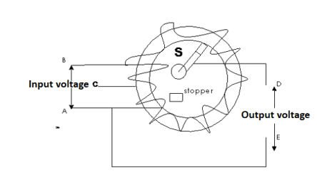
- Weight of copper required in and auto transformer is always less than that of the conventional 2 winding transformer and hence it is cheaper.
- Compact in size and loss costly
- Losses taking place in transformer is reduced hence efficiency is higher than conventional transformer.
- Due to reduced resistance voltage regulation is better than conventional T/F.
Disadvantages
A low Voltage and high voltage sides are not separate, then there is always risk of electric shocks when used for high Voltage Applications.
Applications
- Starting squirrel cage induction motor and asynchronous motor.
- Auto transformer as dimmers tat
- Used as varies to vary a.c. voltage.
|
2.1.1 Electrostatic field, electric flux density, electric field strength, absolute permittivity, relative permittivity and capacitance
- Electrostatic field or electric field:
The region around which a charge or charged body in which the influence
Of electrostatic field / force or stress exist
2. Electric lines of force:
The electric or electrostatic lines of force are imaginary lines which represent the stress distribution of electric field surrounding the charged body.
3. Electric flux ( 
The no of lines of force any particular electric field is called as electric flux measured in coulombs
 =
=  coulombs
4. Electric Flux Density (D)
Flux per unit area measured at right angles to the direction flux
D= |
It is also called as displacement density.
5. Electric Field Strength or Field Intensity or potential gradient
The mechanical force experienced by a unit positive charge when it is placed at that point in the electric field.
E = E = Or E = |
6. Permittivity:
It is the ability with which a dielectric medium permits an electric flux to be established in it called as permittivity
It has 3 types of permittivity
- Absolute permittivity (

Ratio of electric flux density (D) to electric field strength at any point in electric field.
|
2. Permittivity of force space or air or vacuum ( 0)
0)
It is the ratio of electric flux density in a force space or vacuum or air to electric field strength.
|
And  0 = 8.854 X 10⁻¹² F/m
3. Relative Permittivity (
It is the ratio of electric flux density at electric field to electric flux density at force space or air vacuum by same identical condition.
Put value of D and D0 in Equation A
|
Relation between electric flux density and electric field strength (for numerical MCQ’S)
D = But |

7. Capacitance
It is the ratio of charge needed to be acquired in order to attain a potential difference of one volt between the plats.
Or
It is the properly of capacitor to store an electric energy in the form of static charge is called as capacitance
2.1.2 Capacitor, capacitors in series and parallel, energy stored in capacitors, charging and discharging of capacitors (no derivation) and time constant.
Capacitor / Condenser
|
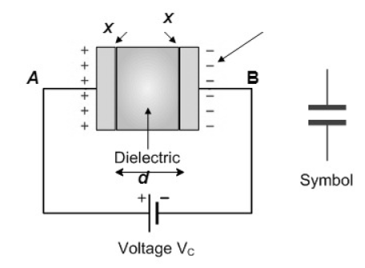
It is an electric component which is capable of storing charge.
Capacitor consist of 2 parallel plates separated by insulating material called dielectric
The ability of a capacitor to store a charge is called as capacitance.
Capacitance of simple parallel plate capacitor with one dielectric
|
Consider a parallel plate capacitor fully charged as shown above.
The area of each plate X and Y is say A
Plates are separated by distance “d”
Let Q be the charge accumulated on plate X then the electric flux passing through the medium
D = Electric field Intensity
We know that D =
Rearranging the terms
But
But Q =
|
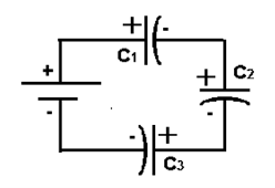
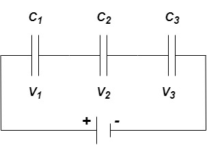
Equivalent capacitor: for MCQ’s numerical capacitor in series
|
V = v1 + v2 =
|

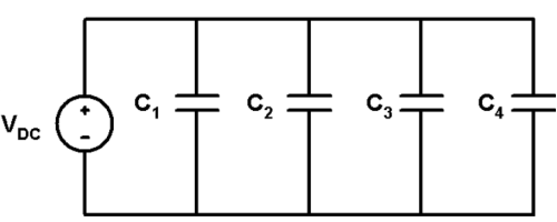
Capacitor in parallel
|
|
Explain different types of capacitors or capacitance of a parallel plate capacitor with composite dielectric
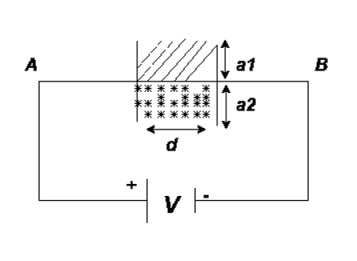
Type 1
|
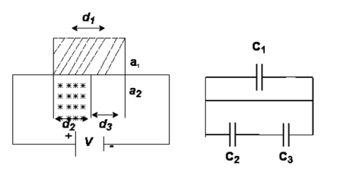
Consider a composite dielectric capacitor with 2 dielectric having relative Permittivity  1 and
1 and  2 , distance between the plate d and separated by dielectric having areas a1 and a2
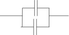
They appear as 2 capacitors connected in parallel as shown below.
|
For n no of slabs Ceg = Type 2 Composite |
|
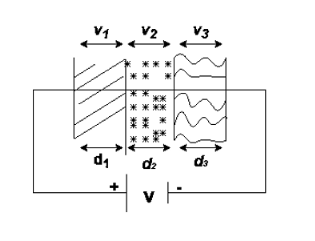
Three dielectrics  placed between the plates having thickness d1, d2 and d3 and let ‘a’ be the area of cross section of plates
Total v = v1+v2+v3
= E1d1 + E2sd2 + E3d3
Now C =
|
Connected in series
|
|
Type 3
|
C = |
=  +
+ 
Explain different types of capacitor based on dielectric material
Air capacitor: in air capacitor dielectric is air. There is set of movable plates interleaved with a set of fixed plats. The distance between the plates can be increased or decreased with the help of movable plates thus changing the value of capacitance they are used for high voltage applications.
- Paper capacitor: in paper capacitor the dielectric used is pertained paper between the plates. The alternate sheets of paper and the metal are coiled together to give concentric layers.
- Ceramic capacitor: Ceramic capacitor have Ceramic material coated by silver on both the sides. Ceramic acts as the dielectric between the metal coating ceramic capacitor are less costly and are compact.
Mica capacitor: Ceramic capacitor have alternate layers of mica sheets and mica foils interleaved together. They are used for high voltage applications.
Energy stored in capacitor
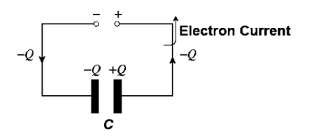
- During charging process of a capacitor transfer of charge take place from one plate to its other plate. Thus, the charge transfer takes place against the opposition presented by the potential difference that exists between the plates.
- The external charging source delivers energy which is stored by capacitor in the form of electrostatic field set up in the dielectric medium.
- At the time of discharging this field well collapse and energy stored is released by capacitor.
Let the capacitor of value C farads be charged to a potential difference of V volts. Let the charge on the capacitance at any instant be “g” Columbus

 work done in shifting a small charge” dg” against the potential difference of ‘V’ volts is given by
But
|
 of a capacitor
|
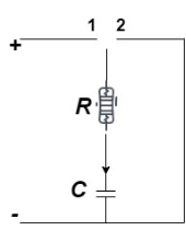
Switch position 
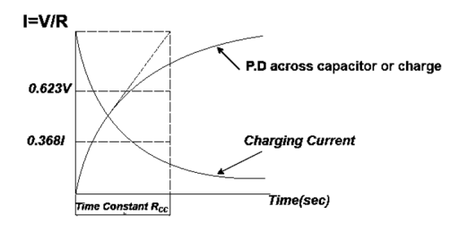
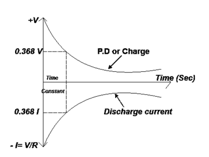
At instant of closing switch, no initial charge on capacitor  potential difference (P.D.) is zero.
Capacitor acquires charge as P.D. i.e. V it rises quickly and then in exponential manner it become to source voltage V.
The charge and P.D. across capacitor achieve steady state after infinitely long period and current becomes zero (almost).
|
Discharging of Capacitor
Capacitor discharger through R with initial current 
As time increase i.e.  the P.D. and the charge gradually decreases exponentially from maximum to zero
|
Charging: (for numerical only) MCQ’S
- Voltage during charging at only instant v = V D- e –E/Rc
Where v = total voltage applied
2. Instantaneous current during charging
3. i = I e-t/Rc
I = initial current curing charging
Where I = VR - charging current
4. Initial rate of rise in potential difference across capacitor = 
Discharging: (For numerical only) MCQ’s
- Instantaneous voltage during discharge v = Ve-t/Rc
- Instantaneous charge during discharging v = Qe-t/Rc
where Q = cv - final value
3. Instantaneous current during discharging i = Ie-t/Rc
Where  discharging current
4. Initial rate of decay of capacitor voltage = 
Time Constant
It is product of resistance and capacitance in circuit.
Or
Time required for potential difference to rise from zero to 0.632 of its final value during charging

Introduction
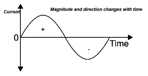
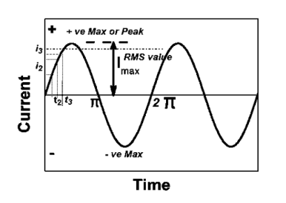
Alternating current is the current which changes periodically both in magnitude and direction
|
2.2.1 Sinusoidal voltages and currents, their mathematical and graphical representation, Concept of cycle, Period, frequency, instantaneous, peak(maximum), average and r.m.s. values, peak factor and form factor.
|
Cycle:
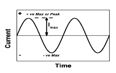
Each repetition of set of positive and negative Instantaneous value of an alternating quantity is called as cycle.
Time period:
The time taken by an alternating quantity to complete its on cycle known as time period.
Frequency:
The numbers of cycle completed by an alternating quantity per second known as Frequency. Measured in cycle/second or that.
Angular Frequency (w):
It is the Frequency expressed in electrical radians per second w = 2 X F or w = 
Instantaneous value:
The value of an alternating quantity at a particular instant is known as Instantaneous value.
Peat to peak value:
The value of an alternating quantity from its positive peak to negative peak

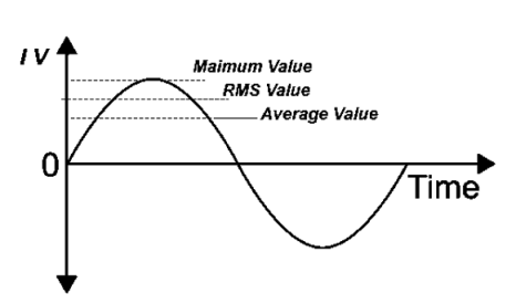
Average Value:
|
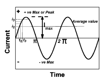
The arithmetic mean of all the value over complete one cycle is called as average value

 =
= 
For the derivation we are considering only hall cycle.
Thus  varies from 0 to ᴫ
i = Im Sin


Solving
We get


Similarly, Vavg=
The average value of sinusoid ally varying alternating current is 0.636 times maximum value of alternating current.
RMS value: Root mean square value
|
The RMS value of AC current is equal to the steady state DC current that required to produce the same amount of heat produced by ac current provided that resistance and time for which these currents flows are identical.
I rms =
Direction for RMS value: Instantaneous current equation is given by i = Im Sin but I rms = = |
= = Solving = = Similar we can derive |
V rms=  or 0.707 Vm
 the RMS value of sinusoidally alternating current is 0.707 times the maximum value of alternating current.
Peak or krest factor (kp) (for numerical)
It is the ratio of maximum value to rms value of given alternating quantity Kp =
|
Form factor (Kf): For numerical “It is the ratio of RMS value to average value of given alternating quality”.

|

|
2.2.2 Phase difference, lagging, leading and in phase quantities and phasor representation.
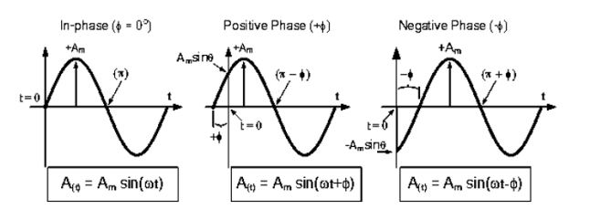
Phase: It is angle made by the (conductor) phases with respect to reference axis. It is denoted by Ø
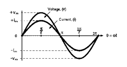
Phase difference: The difference between the phase of 2 alternating quantities is called as phase difference there are
- Positive phase difference + Ø
- Negative phase difference – Ø
- Zero phase difference Ø = 0
We consider always 2 ac quantities. One is voltage and current.
Now as voltage is independent quality i.e. not dependent on load.
 It is always considered as reference quantity
  v=V m sin (w t)
→ Current is load dependent quantity.
Therefore, it creates phase difference according to load.  current equation can be written as 𝑖=Im sin
Case1. Zero phase difference (Ø=0)
Equations
V=Vm sin w t – Reference |
𝑖 = I m sin (w t + 0)  Ø = 0
Ø = 0
|
Case2 +v e phase difference or Leading phase difference (Ø = + v e)
Equation
V= Vm sin w t – Reference
𝑖 = Im sin (w t + Ø)
|
Case 3 - v e phase difference or Lagging phase difference (Ø = -v e )
Equation v = vm sin w t – Reference
= Im sin (w t - Ø)
Mathematical Representation of phases [For Numerical]
The phases can be represented in different ways
- Polar Form
- Rectangular Form
- Trigonometric Form (P - R)
- Exponential Form (R - P)
|
The instantaneous voltage equation V(t) = V m sin (w t + Ø) |
- Polar Form
The instantaneous voltage equation is given by Vt= vm sin (w t +Ø) which can be represented by polar form |
vt =  L Ø
L Ø
where  = peak value
e.g. vt =30 sin (w t + 90 )
)
polar form  < 90
< 90
polar form is suitable for multiplication and division of phases.
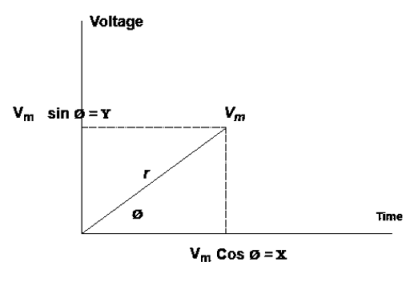
3. Rectangular Form:
The instantaneous voltage equation is given by
Vt = v m sin (w t +Ø) which can be represented by Rectangular Form vt = where X = Y = Vt = v m cos Ø + i vm sin Ø e.g. 30 sin (w t + 90) |
Rectangular form vt = 30 cos 90 + i 30 sin 90
 Rectangular Form is suitable for addition and subtraction of Phases.
4. Trigonometric Form (Polar to Rectangular)
If the phases are given in polar form from  L Ø then it can be represented in
rectangular form by expressing X and Y component in form of  and Ø.
Polar: Vt =  L Ø
L Ø
Rectangular: vt=  + i
+ i where
where
𝑥 =  cos Ø
cos Ø
𝑦 =  sin Ø
sin Ø

5. Exponential Form (R-P)
Given equation Rect : v(+) =𝑥 + i𝑦
Polar: v(+) = 
Where magnetite 
And 
2 Phase added and substrate using Rect. Form
Let V1 = 𝑥1 + i𝑦1 V2 = 𝑥2 + i𝑦2
= (𝑥1 + 𝑥2) + i(𝑦1 + 𝑦2) (V1 – V2) = (𝑥1 – 𝑥2) + i(𝑦1 - 𝑦2) |
For add or subst. If equation. Is given in polar form, we have to connect into Rect. Form and then add/ subtract.
Two phases divide/ multiply by polar
Let V1 = π1 L Ø1 Let V2 = π2 L Ø2 (V1 V2) = (π1 L Ø1) (π2 L Ø2)
| ||||
For dividing
| ||||
| ||||
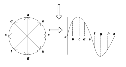
Phases Representation of an Alternating Quantity
- The sinusoidal varying alternating quantity can be represented graphically by a straight line and arrow in the phase’s representation method.
- The length of the line represents magnitude and arrow indicates it direction.
- “The phases are assumed to be rotated in anticlockwise direction with constant Angular speed.”
- One complete cycle of sine wave is represented by one complete rotation of phases as shown below
|
Consider at various position
- At point a the y axis projection is zero
2. At point b the y axis projection 0b sin θ
3. At point c the y axis projection (0C) represent max value of phase
4. Point D, y axis projection is (0ɖ)
5. At point e, y axis projection is zero
|
Now at point “ȴ” on words the phases change its direction  cycle also shifts from the half cycle to –v e half cycle.
2.2.3 Rectangular and polar representation of phasor
- Polar Form
The instantaneous voltage equation is given by
Vt= vm sin (w t +Ø)
which can be represented by polar form
vt =  L Ø
L Ø
where  = peak value
e.g. vt =30 sin (w t + 90 )
)
polar form  < 90
< 90
polar form is suitable for multiplication and division of phases.
2. Rectangular Form:
The instantaneous voltage equation is given by
Vt = v m sin (w t +Ø)
which can be represented by Rectangular Form
vt = 
where X = Y = Vt = v m cos Ø + i vm sin Ø e.g. 30 sin (w t + 90) |
Rectangular form vt = 30 cos 90 + i 30 sin 90
 Rectangular Form is suitable for addition and subtraction of Phases.
Reference Books:
- H Cotton, Electrical technology, CBS Publications
- L. S. Bobrow, ―Fundamentals of Electrical Engineering‖, Oxford University Press, 2011.
- E. Hughes, ―Electrical and Electronics Technology‖, Pearson, 2010.
- D. C. Kulshreshtha, ―Basic Electrical Engineering‖, McGraw Hill, 2009.


