Unit 4
Polyphase A.C. Circuits and Single Phase Transformers
- Poly phase one which produces many phase simultaneously
- Instead of saying poly phase we use 3 ɸ supply there for 3 ɸ system
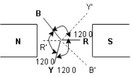
- Generation of electrical supply is 3 ɸ only using alternator (AC generator) by 3 separate winding placed 1200 a part from each other one winding for I phase
 3 windings
3 phase =  = 1290 apart each winding
|
|
Here R is the reference phase globally in generation of 3 Ø ac
Ø = 0
Y is the 2nd phase generated and placed apart from R phase Ø = -1200
B is the 3rd phase generated and placed apart from R phase Ø = -2400
|
Equation
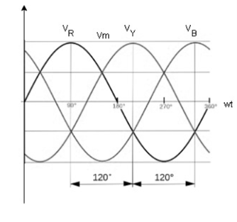
VR = Vm Sin wt VY = Vm Sin (wt-1200) VB = sin (wt – 2400) Or VB = Vm sin (wt + 1200) |
- Advantages of 3 Ø system over single phase
- More output: for same size the output of 3Ø machine is always higher than single 1 Ø phase machine.
- Smaller size: for producing same output the size of 3 phase machine is always smaller than of single phase machine
- 3 phase motor are self-starting as the 3 Ø ac supply is capable of producing a rotating magnetic file when applied are self-starting 1 Ø motor need additional starter winding
- More power is transmitted: in the transmitted system it is possible to transmitted more power using 3 Ø system rather than 1 Ø system, by using conductor of same cross sectional.
- Smaller cross sectional area of conductor
ɡȴ same amount of power is to transmitted than cross sectional area of conductor used for 3 Ø system is small as compared to that for single Ø system.
- Symmetrical or balanced system
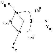
3Ø system in which 3 voltages are of identical magnitude and frequency and are displaced by 1200 from each other called as Symmetrical system.
- Phase sequence:
The sequence in which the 3 phase reach their maximum +ve values Sequence is R-Y-B 3 colours used to denoted 3 phase are red’, yellow, blue.
The direction of rotation of 3 Ø machines depends on phase sequence. ɡȴ the phase sequence is changed i.e. R-B-Y than the direction of rotation will be reversed.
- Types of loads
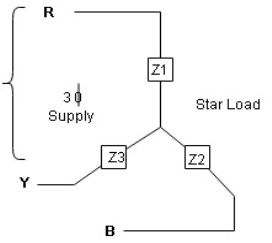
- Star connection of load
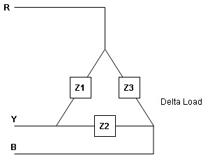
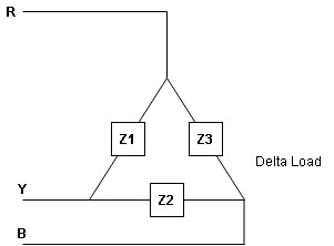
- Delta connection of load
|
|
Balanced load: balanced load is that in which magnitude of all impedance connected in the load are equal and the phase angle of them are also equal
ie Z1  Z2
Z2  Z3 then it is unbalanced load
- Line values and phase Values:
- Line Values: ɡȴ RYB are supply lines then the voltage measured between any 2 Line is called as line voltage and current measured in the supply line is called as line current.
|
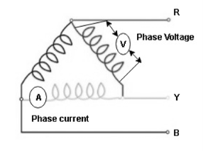
2. Phase Value: the voltage measured across a single winding or phase is called as phase voltage and the current measured on the single winding or phase is called as line current.
|
Derive
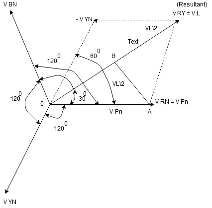
Relation between line value and phase value of voltage and current for balanced (ʎ) star connected load (load can be resistive, Inductive or capacitive)
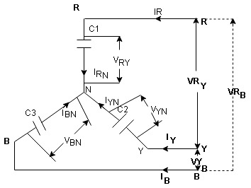
For capacitive load
|
Consider a 3 Ø balanced star connected balanced load capacitive
- Line Value
Line voltage = VRY = VYB = VBR = VL Line current = IR = IY = IB = IL Phase value Phase voltage = VRN = VYN = VBN = Vph Phase current = VRN = VYN = VBN = Vph Since for a balanced star connected load the line current is the same current flowing in the phase
|
- Since the line voltage differ from phase voltage we can relate the line value of voltage with phase value of voltage
Referring current diagram
Bar indicates vector addition
Instead of writing
|
Similarly, other line voltage can be writing as follows. (Resultant)
|
 =
=  -
- 
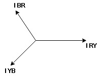
- Phasor Diagram:
Consider equation …..①
|
NOTE : We are getting resultant line voltage by subtracting phase voltage  take phase voltage at reference phase as shown
Cos 300 =
|
|
Drive
- relation between line value and phase value of voltage and current for a balance (
 ) delta connected inductive load
|
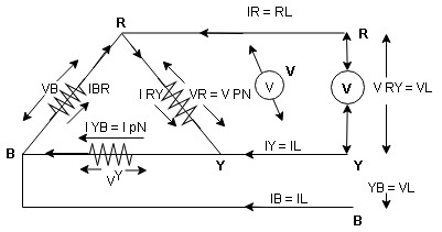
consider a 3 Ø balance delta connected inductive load
- line values
Line voltage = VRY = VYB = VBR = VL Line current = IR = IY = IB = IL Phase value Phase voltage = VRN = VYN = VBN = Vph Phase current = VRN = VYN = VBN = Vph
|
- since the line current differ from phase current we can relate the line and phase values of current as follows
IR + IRY= IRY
Line phase Similarly apply KCL at node Y IY + IYB = IRY … …. ② Apply KCL at node B
|
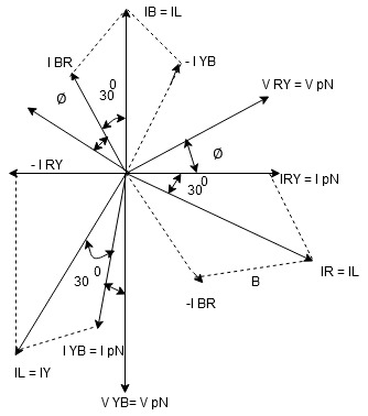
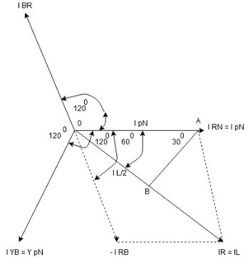
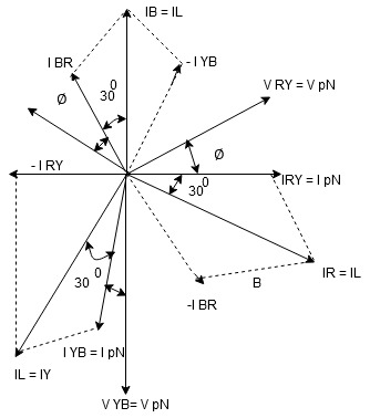
- Phasor Diagram
Consider equation ①
Note : we are getting resultant line current IR by subtracting 2 phase currents IRY and IBR  take phase currents at reference as shown
Cos 300 =
|
- Complete phases diagram for delta connected balanced Inductive load.
|
Phase current IYB lags behind VYB which is phase voltage as the load is inductive
PPh = VPh IPh Cos Ø For 3 Ø total power is PT= 3 VPh IPh Cos Ø …….① For star VL
For delta VL = VPh and IL = PT
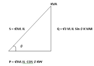
total average power P = K (watts) Total reactive power Q = K (VAR) Total Apparent power S =
|
- Power triangle
|
- Relation between power
In star and power in delta
Consider a star connected balance load with per phase impedance ZPh
we know that for
VL = VPh andVL = now IPh =
And VPh =
Pʎ = Replacing ① in ② value of IL
|
- Now for delta
IPh =
And IL =
P Replacing ② in ① value of IL P
|
Pʎ from …A
We can conclude that power in delta is 3 time power in star from …C Or |
Power in star is  time power in delta from ….D
- Step to solve numerical
For star VPh = For delta VPh = VL 2. Calculate IPh using formula IPh =
3. Calculate IL using relation
IL = IPh - for star
IL =
4. Calculate P by formula (active power)
P =
5. Calculate Q by formula (reactive power) |
Q = |
6. Calculate S by formula (Apparent power)
S = Unit 4 Part B |
I Ø transformers and electrostatics
- Types of transformers
Acc to input supply : I phase and  phase
phase
Acc to construction: core and shell type
Acc to 0/P : step up and step down
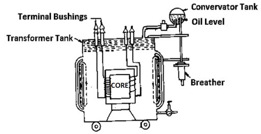
Construction of transformers (study only for MCQs)
|
- Laminated steel core
Material used for core is (silicon steel) it is used for its (high permeability) and (low magnetic reluctance)  magnetic field produced is very strong
The core is formed of (stacks of laminated thin steel sheets) which are electrically isolated from each other. They are typically (0.35 to 0.5 mm thick)
We can used 2 ‘L’ shaped sheets or 2  shaped sheets for laminations
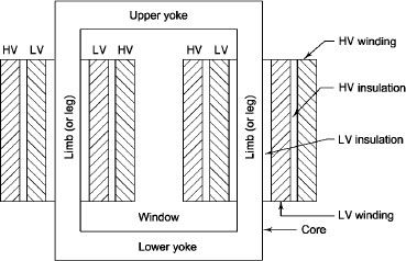
- There a 2 types of winding
- Concentric or cylindrical
- Sandwiched type
- Cylindrical
L.V. = low voltage H.V. = high voltage are mounted on same limb to minimum leakage.
|
L.V. Winding placed inside and H.V. winding placed outside with (proper insulation between the winding as it is easy to insulated L.V. winding) than H.V. winding.
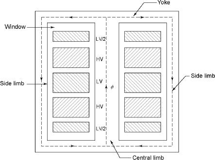
2. Sandwiched
|
The H.V. and L.V. winding are divided into no. of small coils and their small windings are interleaved.
(the top and bottom winding are L.V. coils because they are close to core)
- Transformer tank: wholes assembly of winding and core placed inside the Transformer tank (sheet metal tank) which is filled with Transformer oil or insulating oil which acts as an (insulator or coolant) MCQ
- Transformer oil: (The function of oil is to remove efficiently the heat generated in core and in winding)
- Moisture should not be allowed which creeps the insulation which achieved by closed Transformer tank.
(To increase cooling surface are tubes or fins are provided)
- Conservator tank: above tank T/F tank there is one small tank in which same empty space is always provided above the oil level. (this space is required for oil to expand or contract due to temperature change) MCQ
However, during contraction outside air can have moisture which will deteriorate the insulating properly of oil.
- Breather: the air goes in or out through the breather (To reduce the moisture content of their air. same drying agents such as (silica gel or) calcium chloride) is used in the breather (The dust particles present in air are also removed by breather)
- Buccholz Relay: (for incipient (slowly increasing) faults
There is pipe connecting rain tank and conservator. On the pipe a protective device called Buccholz Relay is mounted.
When the Transformer is about to be faulty and draw range current the oil becomes very hot and decompose.
During this process different types of gases are liberated. (The Bucchoz Relay get operated by these gases) and gives an alarm to the operator. ɡȴ the fault continues to persist then there lay will trip off main circuit breaker to protect the Transformer.
- Explosion Vent:
An explosion Vent or relief value is the bent up pipe filled on the main tank.
(The explosion vent consist of aluminium of oil) when the T/F becomes faulty the cooling oil get decomposed and various types of gases are liberated
(ɡȴ the gas pressure exodus certain level then the aluminium of oil (diagram) in explosion vent will burst) to release pressure. The will save main tank from getting damaged.
- Single phase transformer - for MCQs
(Symbol and principal of operation)
It is a static device which can transfer electrical energy from one ac circuit to another ac circuit without change in frequency
It can increase or decrease the voltage but with corresponding decrease or increase in current
It works on Principle 
“Mutual Induction”
A major application of transformer is to increase voltage before transmitting electrical energy over a long distance through conductors and to again reduce voltage at place where it is to be used.
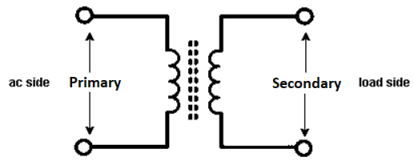
Symbol
|
- Primary winding : (ac supply side) For MCQs
The winding which is connected to supply is called primary side
2. Secondary winding : (load side) for MCQs
The winding which is connected to load is called as secondary winding
- Working: For MCQs
It works on principle of mutual Induction i.e. “when 2 coil are inductively coupled and if current in one coil is changed uniformly then an emf get induced in another coil”
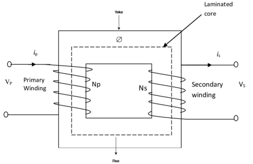
- When alternating voltage V1 is applied to primary winding am alternating current I1 flows in it producing alternating flux in the core.
- As per Faradays Law of Electromagnetic Induction 1 an emf E1 is induced in the primary winding E = N1

- The emf induced in the primary winding is nearly equal and opposite to applied voltage V1
- Assuming leakage flux to be negligible almost whole flux produced in primary winding links with secondary winding thence emf induced in the secondary winding E2 = N2

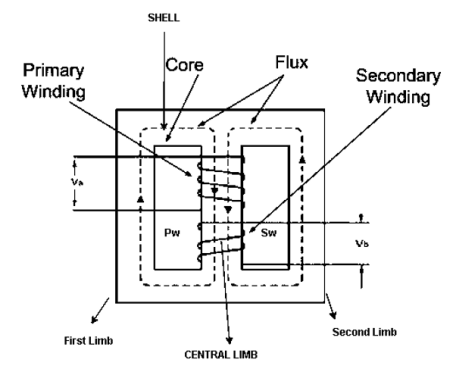
- Core and shall type transformers
Core Diagram
|
Shell Diagram:
|
|
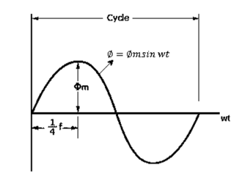
As primary winding excited by a sinusoidal alternating voltage an alternating current flows in the winding producing an alternating varying flux Ø
Ø = Øm sin wt As per Faradays Law of Electromagnetic Induction emf E1 is induced E1 = N1 E1 = N1 = - N1 Øm w Cos wt Sin (90-wt) = - Sin (wt-90)
Max value of E1 = E max Is when Sin (wt-90) = E1 max =
Hence rms value of induced EMF in primary winding E1 rms =
E2 = 4.44 F Ø m N2 |
Transformation Ratio for MCQs numerical
K = 2. Turns Ratio: ratio of secondary turns to the primary turns Turns ration = 3. Current ratio : ratio of primary current to secondary current =
For step up transformer N2 For step down transformer N2 |
- Losses in a Transformer [6m]
There are 2 types of losses occurring in a transformer
A) 1. Core loss or Iron loss
B) 2. Copper loss
- Core losses:
- This loss is due to the reversal of flux
- The flux set up in the core is dependent on the i/p supply
 as the i/p supply is constant in magnitude
  the flux set up will be constant and
  core losses are also constant.
 - Core losses are voltage dependent loss they can be subdivided in 2
1 Hysteresis loss
2 reedy current loss
- Hysteresis loss: The iron loss occurring in the core of T/F due to the Hysteresis curve of the magnetic material used for core is called as Hysteresis loss.
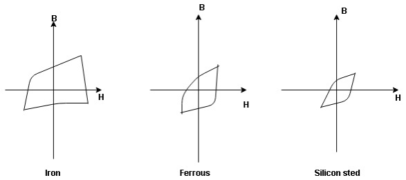
Hysteresis curve is the curve as loop which shows the properly of magnetic material to lag the flux density B behind the field Intensely H
|
Above is the 3 different loops (Hysteresis of 3 diff. Materials)
 the selection of magnetic material for the construction of core depends upon Hysteresis loop of that material having tall and narrow Hysteresis loop is selected for the T/F core
 silicon Steel
Hysteresis loss depends on fold factor
PH = KH. Bm1.67 F Where KH = constant (Hyst) |
Bm = max Flux density
F = Frequency
 = Volume of core.
2. Reedy current loss:
This loss is due to the flow of reedy (circular) current in the core caused by induced emf in core
PE = Ke Bm2 f2 t2 v – watts
Where
Ke = reedy current const.
t = thickness of core
It can be reduced by using stacks of laminations instead of solid core
B] Copper loss : PCU
The Copper loss is due to resistance of the primary and secondary winding
It is load dependent / current dependent loss
As load on a transformer is variable (changing)  current changes
  copper loss is a variable loss
Primary secondary Total C is loss = I12 R12 + I22 R22 | ||
Copper loss depends upon load on T/F and is proportional to square of load current or KVA rating of transformer F.L = full load
= (0.5)2 PCU F.L. | ||
Or PCu ( load) = (
 )2 PCu F.L
Vat ampere rating / rating of transformer for MCQs
As the rating decides the O/P power of any machine and the o/p power depends upon the efficiency of that machine which depends upon losses of the machine
- As the transformer losses depends on voltage and current, the rating of transformer is specified as the product of voltage and current called as V I rating / VA rating
- The rating of T/F indicates the output power from it but transformer load is not fixed
Hence rating of transformer is not expressed in terms of power but in terms of product of voltage and current called as VA rating
The rating is expressed as KVA rating
Full load secondary current
|
Voltage regulation: (for MCQs numerical)
The change in secondary terminal voltage from no load to full load condition expressed as fraction of no load secondary voltage is called as voltage regulation
|
Efficiency: it is the ratio output power to input power of transformer
| ||
Output power = input power – total loss
O/P power = KVA Or = V2 Losses = Pi + PCU (F.L) = iron + copper loss
| ||
Maximum efficiency – for numerical:
The efficiency of T/F is maximum when copper loss equates iron loss this is the condition for max efficiency
i.e. Pi = PCU
Where KVA at max n given = Full load KVA
|
- Direct lading test for finding efficiency and regulation of a 1 KV 230v/ 1Ø 50 H transformer
1KVA =
Rating of approaches ammeters
Secondary A2 = (0 – 5) Amp
Primary V1 = 0 - 300 V Secondary V2 = 0 - 300 V
Similarly w2 = 1500 w , 5A , 300 v |
Connections
- The primary of T/F is connected to a.c. supply of rated voltage through instruments like ammeter voltmeter and wattmeter
- A variable load is connected across the secondary. One ammeter (A2), Voltage (V2) and wattmeter (w2) are also inserted on secondary side
Procedure:
By varying load in suitable steps, readings are taken on all meters from no load to full load (2.5% of full load)
Observation table
Sr no. | primary |
|
| Secondary |
|
|
| V1 | I1 | W1 | V2 | I2 | W2 |
1 |
|
|
|
|
|
|
2 |
|
|
|
|
|
|
- Calculation:
Efficiency = = |
- Regulation:
Find no load vtg E2
remove the load and measure the reading of V2 meter ew will get n load vtg E2
Now connect load and measure V2 this is now the load voltage
For each reading E2 will be same but V2 will change acc. To load |
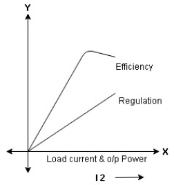
- Form Results Plot graph for efficiency and regulation against I2 and O/P power W2
|
Auto Transformer
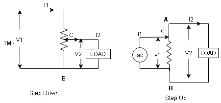
An auto Transformer is a special types of transformer such that a part of the winding is common to both primary as well as secondary
It has only One winding wended on a laminated magnetic core
With the help of auto Transformer the voltage can be stepped up and stepped down at any desired value
|
Fig A shows auto T/F as step down T/F variable terminal B C is connected to load and it acts as secondary wag.
The position of point C is called as topping point can be selected as per requirement
Fig. B show auto T/F as step up T/F variable terminal B C is connected to supply side i.e. ac side and it acts as secondary winding
The operating principle of auto Transformer is same as that of 2 winding Transformer
Advantages
- Weight of copper required in an auto Transformer is always loss than that of the conventional 2 winding Transformer and hence it is cheaper
- Com [act in size and loss costly.
- Losses taking place in Transformer is reduced hence efficiency is higher than conventional Transformer.
- Due to reduced resistance, voltage, regulation is better than conventional T/F.
Disadvantage:
As low voltage and high voltage sides are not separate then there is always risk of electric shocks when use for high vtg. Applications
Applications
- Starting squirrel cage induction motor and synchronous motor.
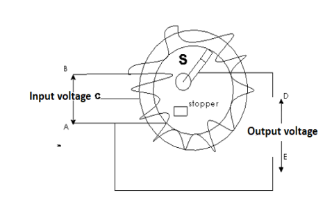
- Auto transformer as dimmer stat
- Used as vari ac to vary a. c Voltage
|
Reference Books:
- H Cotton, Electrical technology, CBS Publications
- L. S. Bobrow, ―Fundamentals of Electrical Engineering‖, Oxford University Press, 2011.
- E. Hughes, ―Electrical and Electronics Technology‖, Pearson, 2010.
- D. C. Kulshreshtha, ―Basic Electrical Engineering‖, McGraw Hill, 2009.
