Unit - 6
Work, Power, Energy
Definitions: -
1] Electric charge [Q]: A material suffering a deficiency of electrons is +vely charged and possessing surplus of electrons becomes –vely charged. Thus total deficiency or excess of electrons in a body can be called charge. Unit of charge is coloumb denoted by Q.
1 Coloumb = 6.24*10^18 electrons.
2] Electric Current [I]: It is defined as rate of flow of electrons or rate of transfer of charge [Q] per unit time, unit of current is ampere I=Q/t Amps
3] Relation between Q and I
I=Q/t |
Where Q=charge in coloumbs
t=time in secs
4] Potential Difference [P. D]: The difference between the electrical potentials (or pressure) at any two given points in the electrical circuit is known as potential differences .it is measured in volts.
5] Electromotive force: EMF
It is force produced due to potential differences which tends to produce electric current in a circuit called as EMF. Its unit is vat.
6] Electric potential [V]: The work done against the force of repulsion to bring a charge closer to each other is called as electric potential.
7] Resistance: It is opposition to the flow of current. unit is Ω ohm R=V/I Ω |
- Factors affecting Resistance
Resistance depends upon the following factors by formulae R= l/a
l/a
1]Length: Rα l as u length ↑R also↑
2] Areas (a) Rα 1/a as area (↑) then R(↓)
3]Type and nature of material: Different materials have different
Resistances depending upon the availability of free electrons.
4] Temperature: The temperature of conductor affects its resistance
8]Specific resistance[r]: The resistance of a specimen piece of material having unit length and unit cross sectional area is known as sp. Resistance or resistivity of that material denoted by ‘ ’unit is ohm -m
 =R x.a/l Ω*m^z/m=Ω-m
9]Conductance [G]: It is reciprocal of resistance .it is defined as the ratio of R resistance to the square of the impedance G=R/z^2.its unit is Siemens.
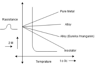
Effect of temperature on resistance of different material
|
1] (Positive temperature coefficient)
->Metals(pure)metals have positive temperature coefficient of resistance as resistance of metal increases with increases in temperature
->as temperature increases the metal low gain energy and they vibrate higher velocity blocking the path of flow of electrons
->thus the conductance decreases and resistance increases (eg Copper, Aluminum)
2](Negative temp coefficient)
Insulator the resistance of insulator decreases linearly with increases in temp.
->when the temp increases some electrons gain thermal energy and become fiers for conduction. Hence resistance decreases as temp increases. e g Rubber
3] Alloys (combination of 2 metals)
The resistance of alloys increases with increases in temp but rate of change of resistance is less than that of metals. e.g. bronze, steel
4](Constant temp coefficient)
Special Alloys: Alloys like eureka, manganin constantan have constant temp. Coefficient that is no change of resistance for change in temperature.
5]Semiconductors: semiconductors are the materials having conductivity between that of metals and insulators i.e. for a specific temperature the resistance increases and after a specific temperature resistance decreases eg. Silicon, Germanium.
Temperature coefficient of resistance-(α)
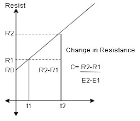
Definition of RTC: The resistance temp coefficient at 0^0c is the ratio of change in resistance per 0c to the resistance at 0^0c i.e. Ro
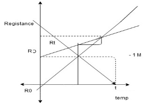
Derivation: the change in resistance of a material with rise in temp can be empresses by means of the temp coefficient of resistance. consider a conductor having resistance i.e.(Rt-Ro) 1] is directly proportional to initial resistance (Ro) 2] directly proportional to the rise in temp t^0c 3]and also depends upon the nature of the material
Rt-Ro α Ro Rt-Ro α ∆t or(t-o) Rt-Ro α Ro(t-o) Rt-Ro = α Ro(t-o) |
|
Rt=Ro + αoRo(t-o) |
Rt=Ro (1+ αo(t-o))
|
Where αo is a constant and is called temp coefficient of resistance of 0^0c .value depends upon type and nature of material and temp.
Αo=Rt-Ro/Ro(t-o) or∆ t -measured in /^0c
Effect of temp on temp coefficient of resistance
*Prove that, α2=α1/1+α1[t2-t1] Or α1-α2=α1α2(t2-t1) |
-let R1 and R2 be the resistance of a conductor at t1^oc and t2^oc resp. and α1 and α2 be the corresponding temp coefficient.
-Suppose the conductor is heated from one initial temp t1^oc to a final temp t2^oc.
R2=R1[1+α1(t2-t1)] -1 The same conductor is now coated from t2^oc to t1^oc R1=R2[1+α2(t1-t2)] -2 |
Substitute equations 2 in equation 1 ⸫α2=R2[1+α2(t1-t2)] [1+α1(t2-t1)] 1= [1+α2(t1-t2)] [1+α1(t2-t1)] 1/1+α1(t2-t1) =1+α2(t1-t2) 1/1+α1(t2-t1)-1=α2(t1-t2) 1-1-α1(t2-t1)/1+α1(t2-t1) =α2(t1-t2) Now -α1(t2-t1) can be written as α1(t1-t2)
⸫α1(t1-t2)/ 1+α1(t2-t1)= α2(t1-t2)
⸫α2=α1/1+α1(t2-t1)
If temp changes from 0^oc to t^oc ⸫ replace α2 by αt and α1 by αo αt=αo/1+αo(t-o) =αo/1+αo(t) nowα2=α1/1+α1(t2-t1) α2(1+α1(t2-t1))=α1 α2+α1 α2 (t2-t1))=α1 ⸫α1-α2=α1 α2 (t2-t1) -Hence proved |
Effect of Temperature on Resistivity
Resistivity of material increases linearly with the increases in temp
If temp changes from 0^oc to t^oc
|
Definition: Insulation resistance may be defined as the resistance offered by the insulating material to the flow of leakage current through it.
Insulation resistance= Ri=V/Il |
It is measured in MΩ
- Insulation resistance of a cable
|
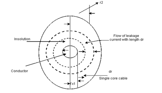
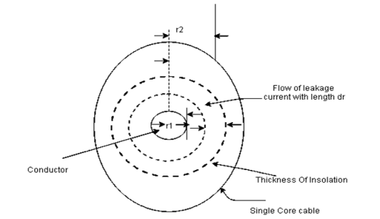
Fig shows a single case cable in which conductor [small circle] is completely covered by layers of insulating material [region between inner and outer circle].
- Consider a leakage current flowing in radially outward direction [dotted circles] from the conductor.
- Consider the thickness of leakage current be dr as shown in fig,
- It is the length of cable in l. then the cross sectional area perpendicular to the flow of current in the surface area i.e 2πrl⸫li=dr and a=2πrl
⸫small resistance of section of insulator
dRi= = The total insulator resistance Ri can be obtained by integrating dRi from inner radius r1 to the outer radius r2 Ri= = = = = Where r1=radius of conductor and r2=radius of cable including conductor and insulator. Thickness of insulator = r2-r1 |
|
Effect of temp and moisture on insulation resistance:
The insulation resistance decreases with increases in temp when then temp. of the material increases some of the valence electrons jump in the conduction band and become free for conduction. Hence conductivity increases and insulation resistance decreases with increase in temp.
When insulating material absorbs some moisture it provides a path for leakage current to flow. Hence the insulation resistance decreases.
Work power and energy in an electrical system
- Work: electrical work is said to done when a charge is transferred from one point to the other point through a potential diff.
Work done =change *potential diff
W=Q*V. =It*V =I2Rt V^2/R *t -SI unit is joule |
- Power: Power is defined as product of voltage and current
⸫ P=VI =I^2R =V^2/R -walts
⸫ Energy =power * time E=p*t =V*I*t -walt sec or joule
Now1kwH =1000 walt hour = 1000*3600 |
1kwH=36*10^5 walt-sec/J
Work, Power and energy in a mechanical system
-> Work: work is said to be done on a body when a force acts on it and the body moves through the same distance.
W=F*d - Joule ->Power: It is the rank of doing work ⸫ p=work done/t -J/sec ->Energy: It is capacity to do work K.E= ½ m*v^2 P.E= m*g*h where g=9.81m/s^2 |
-unit is joule
Heat and Energy in a thermal system
The amount of heat gained or lost by a body is diff in diff condition and its depends on the following factors
i]The amount of heat gained or lost by a body is directly proportional to its mass(m)
ii] The amount of heat gained or lost by a body depends upon change in temp (t2-t1)
iii] The amount of heat gained or lost depends upon the nature of material of body ⸫amount of heat in J=m(t2-t1) materials
The unit of heat is calorie or kcal.
1kcal=1000 calories 1 cal=4.186 joule 1kcal=4186 joule 1 joule=1/4.186=0.2389cal 1kwlt=36*10^5 joule =36*10^5*0.2389cal =860 k cal |
Specific heat capacity:
The amount of heat required to change the temp of unit mass of a material by 1^0c is called its specific heat capacity.it is denoted by C
C=amount of heat required by body/mass of body*change in temp
C=Q/m(t2-t1) -J/kg^ok Or Q1= mC(t2-t1)-joule……………(1)
|
Now specific heat capacity of water is 4186 J/kg^oci.e 4186J of heat is required to change the temp of 1kg of water bye 1^oc
Specific latent heat: [L]
The heat required by a body to convert
1]-> from solid to liquid state at constant temp-sp.latent heat of fusion
2]->from liquid to gaseous state at constant temp-sp.latent heat of rapourisation
Now sp.latent heat of fusion of material is 720 J/kg
Means 720 joules of heat is required to change the state of 1kg of material from solid to liquid at constant temp.
i.e its melting point.
⸫ L=Q/m ⸫J/kg Q2=m*L…….(2) Where L=sp.latent heat of material -unit is J/kg ⸫ Total heat from (1) and (2) =Q1+Q2 =mc(t2-t1)+mL |
conversion of Energy from one form to another
when conversion take place some energy is lost in form of heat.
1] Electric to mechanical->motors, cranes, pumps, lifts, locomotion etc.
2] Electric to thermal water heaters
3] Mechanical to electric: electric generator
4] Thermal to mechanical: A diesel engine

*Input e1 energy---Device los--output e0 energy
e1 e0
⸫ Output energy=Input-losses
Or Input= Output + Losses
⸫ Efficiency of any system is defined as ratio of output energy to the input energy N=e0/e1 |
- Cell: A device which is used as a source of emf and which works on the principle of conversion of chemical energy into electrical energy is called cell.
- Battery: The combination of various cells to obtain desired voltage level is called as a battery.
- Electrolyte: Which undergo decomposition due to the flow of electrons. Basic electrical energy generation in cell.
->In any cell 2 different conducting materials are immersed in an electrolyte. The chemical reaction results in separating charges.
The charges accumulate on the conductor. Such charged conductors are called as electrodes.
+ve charged electrodes-> anode
-ve charged electrodes-> cathode.
->Thus charged accumulated on electrodes creates potential difference between 2 conductors.
->the conductor ends are marked as +ve and –ve and connected to load. Thus chemical energy is converted into electrical energy. Hence cell is an electrochemical device.
Types of cells
1) Primary 2) secondary
 Primary Secondary

1) Electrical energy indirectly obtained 1) Electrical energy is already present
from chemical energy in the cell in formed chemical
energy and then converted to
electrical energy
2) Chemical actions are irreversible 2) Chemical actions are reversible
(Can’t be recharged)
3) cell is replaced when it goes down 3) cell is recharged back
4) Polarization is present 4) Polarization is Absent
5) Low Efficiency 5) High Efficiency
6) Capacity is low 6) Capacity is high
7) Less cost 7) High initial cost
8) No maintenance is required 8) frequent charging required.
1) positive electrode i.e Anode
2) negative electrode i.e cathode
3) Electrolyte
4) Separator.
Lead acid battery
- construction
|
1) Positive plate or anode: It is lead peroxide (fbo2) plate of chocolate dark brown color
2) Negative plate or cathode: It is made up of pure lead(pb)which is grey in color
3) Electrolyte: for necessary chemical action solution of sulphuric acid
(H2So4) is used as electrolyte.
4) Separators: the positive and negative plates are arranged in groups and are placed alternately. The separators are used to prevent them from coming in contact with each other resulting in short circuit of cell.
5) Plate connector: The number of –ve and +ve plates are assembled alternately. To connect the positive plates together separate connectors are used which are called plate connectors. The upward connections of the plate connectors are nothing but the terminals of cell.
6)Vent plug: These are made up of rubber and screwed to the cover of cell. It functions to allow the escape of gases and prevent escape of electrolyte.
Charging and discharging of lead acid battery.
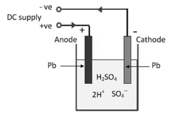
1] When the current is passed for the first time through electrolyte, the H2o in the electrolyte is electrolyzed as
H2o->2 H+o-
- Hydrogen ion is positively charged get attracted towards one electrode which acts as cathode. The hydrogen does not react with lead electrode hence retains its original state and color
- The oxygen ion as negatively charged gets attracted towards other lead plate which acts as anode oxygen combines with lead and form lead peroxide(pbo2) this results in dark brown in color.
- Hence there exists a potential difference between (+ve) anode and (-ve) cathode which is used to drive external circuit.
Discharging
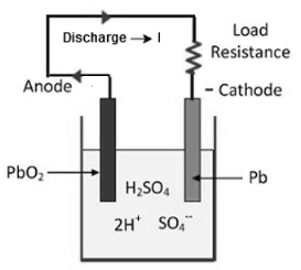
When external supply is disconnected and a resistance is connected across the anode and cathode then current flows through the resistance, drawing an electrical energy from the battery this is discharging.
|
Recharging:
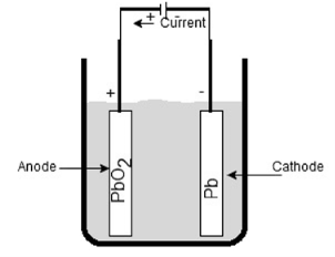
The cell provides the discharge current for limited time and it is necessary to recharge it after regular time interval. Again an emf is injected through cell terminal with help of external supply.
|
Rating of lead acid Battery.
1) The capacity is about 100 to 300 ampere hours.
2) The voltage is 2.2v for fully charged condition.
3) The cost is low.
4) The internal resistance is very low.
5) The current rating is high.
6) The ampere hour efficiency is about 90 to 95% with 10-hour rate.
Maintenance and precautions to be taken for lead acid Battery.
1) The battery must be recharged immediately when it discharges.
2) The level of electrolyte must be kept above top of plates.
3) The rate of charge and discharge should not exceed as specified by manufacture.
4) Maintain specific gravity of electrolyte between 1.28 to 1.18.
5) The loss of water due to evaporation and gasing must be made up using only distilled water.
6) The connecting plugs should be kept clean and properly heightened.
7) It should not be discharged till its voltages falls below 1.8V
8) It should not be kept long in discharged condition.
9) The temp of battery should not exceed 45^oc otherwise plates get deteriorate rapidly.
10) The battery terminals should not be shorted to check whether battery is charged or not.
Applications
1. In emergency lighting systems.
2. In automobiles for starting.
3. UPS systems
4. Railway signaling
5. Electrical substations and power stations.
6. For compensating feeder drop in case of heavy loads.
7. For energizing trip coils in relays and switch gears.
Lithium Ion Battery:
The lithium Ion battery works on the principle of movement of lithium ions from electrodes.
Construction
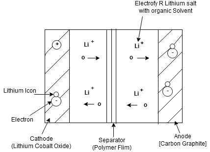
- The lithium ion battery is made up of an anode, cathode, separators, electrolyte and 2 current collectors (+ve and -ve)
- Anode->lithium ion uses carbon electrode as its anode with a current collector of thin copper fail.
- Cathode->It uses lithium cobalt oxide commonly used for cathode with the current Collector made up of thin aluminum fail.
- Separator-> A separator is a fine porous polymer film.
- Electrolyte-> It is the solution based on a lithium salt in an organic solvent
Bothe the electrodes are made up of materials which can “intercalate” or “absorb” the lithium ions
|
Working:
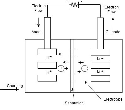
Lithium ions are inserted in cathode
- for charging the battery is connected to an external power supply.
- due to this oxidation occurs at the cathode and it loses electrons which are negatively charged
To maintain the charge balance in the cathode equal no of lithium ions are already dissolved in electrolyte solution.
- The lithium ions travel through electrolyte and reach to anode
- the separator used does not allow the electrons to flow through an electrolyte. The electrons travel through the external wire and reach to anode from cathode.
At anode, the electrons get tied with lithium ions
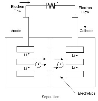
- At time of discharging, the opposite reaction occurs
- Anode releases electrons and ions
- ions get dissolved in electrolyte and electrons travel from cathode to anode through external circuit.
- due to flow of electrons from the external circuit the current is established and device connected to battery is operated.
- when the cathode is full of lithium ions the discharging stops and battery needs to be recharged again.
|
|
Advantages
1) Cell voltage is high which is about 3.6 v less no of cells is required if high voltage is required.
2) The battery is light in weight and compact in size
3)It holds charge for longer period.it only loses 5% of its charge/month
4) It is not required to discharged it completely before charging
5) It has built in protection to prevent overheating.
6) It is rechargeable battery
Disadvantage
1) Its performance is affected due to high temp.
2) Not possible to recharge if it is complete discharged.
3) It is costly
4) It can burst into flames if separators get damaged.
5)It requires protection circuit to maintain voltage and current within safe limits.
Applications
1) Used in cameras and calculators
2) Used in mobile phones, radios and laptops.
3) Used in aerospace applications
4) Used in electric vehicles and mine detectors
5) Used in toys and rechargeable flash lights
Battery efficiency
It is defined as ratio of output during discharging to the input required during charging
1] Ampere hour efficiency or Quantity n
It is defined as ratio of output in ampere hours during discharging to input in ampere hours during charging It is denoted as nAH
nAH=Amp Hr on discharge/ Amp Hr on charge
%nAH= [current* Time on discharge/current* Time on charge] * 100
2] Watt-hour efficiency
It is defined as the ratio of o/p in watt hours during discharging to the i/p in watt hours during charging denoted by nWH
nWH= watt hours on discharge/watt hours on charge
%Nwh= [voltage during discharge] *[current*time at discharge]/
Voltage during charge *[current *time at charge*100]
= nAH *Average voltage during discharge/Average voltage during charge
Concept of Depth of discharging:
-> The depth of discharging is a key factor for any battery. It is denoted by DoD
-> It indicated the degree to which the battery can be discharged to certain minimum voltage from its full state of charge.
->The depth of discharge gives the indication that up to which level of discharge, the battery capacity can be used safely.
-> DoD is defined as the capacity in Ampere Hours(Ah)that is discharged from a fully charged battery, divided by battery nominal capacity.
-> DoD is normally represented in %
-> For example if a 200Ah battery is discharged at 90A for 30 minutes then its depth of discharge is
DoD= (30/60*90*1/200) *100
= 22.5%
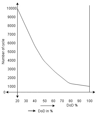
->The depth of discharge is important because the life span of many batteries such as lead acid battery and lithium ion battery depends heavily upon the number of charge and discharge cycles.
-> If the DoD is high then life span of battery gets shortened
For Example, a battery may have 5000 cycles at 20% DoD but only 1500 cycles at 80% of DoD as shown in below graph
|
- Grouping of batteries
1] A single battery is not sufficient to provide the necessary voltage in many causes. Thus numbers of batteries are connected in to obtain desired voltage and current
1) Series grouping of batteries
2) Parallel grouping of batteries
3) Series parallel grouping f”
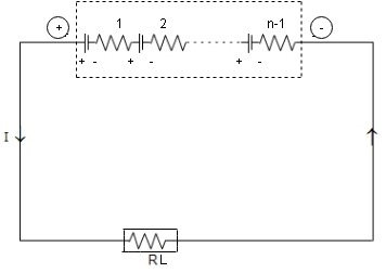
- Series Grouping
|
I= Total voltage/ Total resistance = V/R1=nE/RL+nr -Ampere
E= EMF of each batteries r= Internal resistance of each battery V= Total voltage =n*E volts RT=Total resistance =Load+ Batteries =RL+ n*r |
In series circuit current remains same. So this method does not improve current capacity. The current capacity is same as that of each battery. Connected in series. But voltage can be increased by increasing number of batteries n
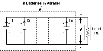
- Parallel Grouping
|
- In this method positive terminal of batteries are connected together and negative terminals are connected together as shown above.
- The terminal of each battery must be same as E
V= Battery voltage= E= emf
R= Internal resistance of each battery
In=current through n^th branch
I= Total current
I= I1+I2+……+In
*In parallel grouping the voltage remains the same but by increasing no batteries
The current capacity can be increased.
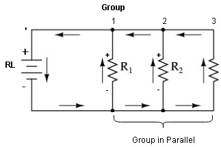
- Series Parallel Grouping
|
*Each group is a series combination of batteries as shown in above fig. and various groups are connected in parallel.
->This is used to satisfy both, voltage and current requirement of load.
- Safety precautions in Battery maintenance (Lithium Ions)
1) Person doing the maintenance must be authorized person.
2) Must have protecting equipment’s such as goggles, chemical resistance gloves, apron and shoes.
3) Before entering battery room ensures that the ventilation system is operable and in service.
4) Verify that the UPS is off and power cord is disconnected from source.
5) Verify circuit polarities before making the connection.
6) Ensure that sufficient water facilities are available nearby.
7) Never connect cell in series a parallel. they do not have identical o/p voltage
8) Use protective devices while charging or discharging
9) Use temp sensors while charging or discharging
Reference Books:
- H Cotton, Electrical technology, CBS Publications
- L. S. Bobrow, ―Fundamentals of Electrical Engineering‖, Oxford University Press, 2011.
- E. Hughes, ―Electrical and Electronics Technology‖, Pearson, 2010.
- D. C. Kulshreshtha, ―Basic Electrical Engineering‖, McGraw Hill, 2009.
