Unit - 4
Electronics Instrumentation
Digital Multimeter :
- A Multi meter the most common measuring instrument. The name comes from multiple meter. There are two common types of Multi meter.
- The multimeter (DMMs) are the most common Measurement readings are displayed as numerical values on the LCD display. The display also alerts you to any pertinent symbols and warning.
- Digital meters on the other hand offer high accuracy have a high i/p impedance and are smaller in site.
|
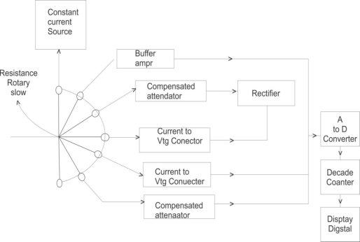
An instrument which is capable of measuring a.c. and d.c voltages a.c and d.c. current and resistances over several range is called digital multimeter.The various measurement possible by DMM are resistance a.c voltage and current d.c voltage and current.The selection of the parameter is possible with the help of rotary switch connected to i/p probes of DMM.
- Resistance Measurement : The rotary switch is in position 1 and resistance is connected to input probes. The constant current source Drives a current through unknown resistance. This produces Vtg across resistance which is directly proportional to the resistance. It is given to the buffer amplify and then to analog to digital converter.The ADC converts it to equivalent digital signal and it is displayed with the help of digital display a.c voltage measurement : The rotary switch is in position 2 and i/p a.cvtg is applied to probes if it is above the selected range it is attenuated with the help of compensated attenuator It is rectified to produce proportional d.c vtg then it is given to ADC which display it in volts
- A.c current measurement : the rotary switch is in position 3 and unknown current is applied across i/p probes it is converted to proportional vtg using current to vtg convertors
|
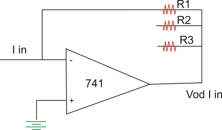
This I V converter is op-amp circuit as shown above. The op-amp/p current is zero hence I in flows through R1 and drop across R1osVo hence vtg o/p  the resistance R1 R2 and R3 are used for the proper range selection. This vtg is rectified and then given to ADC which sisplays the current in amperes.
3. D.c current measurement : The rotary switch is in position 4 and unknown d.c current is applied across i/p probes this vtg is given to ADC without rectification as this is proportional to d.c current ADC display it in amperes on digital display.
4. D.C voltage measurement : The rotary switch is in position 5 and unknown vtg is applied across i/p probes it is attenuated and directly given to ADC display it in volts.
Specifications of Digital Multimeter :
- D.C Voltage : this includes various d.c vtg ranges available along with the resolution and accuracy
- A.c Voltage : this includes various a.c vtg ranges available along with the resolution and accuracy.
- A.C current : this includes various a.c current ranges available along with the resolution and accuracy.
- Resistance : this includes the available resistance range typical six range are available from 200Ω to 20 MΩ the accuracy is
 0.1% of reading + two digits + 0.002Ω on the lowest range.
 - Input Impedance : The i/p Impedance is about 10 MΩ on all the range
- Normal mode noise rejection : this indicates the ability of the meter
It is greater than 60 dB at 50 HZ while the common mode noise rejection is greater than 90 dB at 50 HZ and greater than 120 dB at d.c
7. Overload protection : The overload protection of 1000 V d.c and 75 0ɤ.m.s. a.c is provided.
8. Diode test : The vtg drop across the diode can be measured for which 1 mA + 10% of constant current source is used.
9. Conductance : It can display Conductance in siemens
10. Relative Reference : when RF1 button is pressed the displayed reading is stored as a reference and then subtracted from the subsequent readings to indicate only amount of deviation from the reference.
11. Frequency : The frequency ranges is 200HZ to 200 kHZ auto selection.
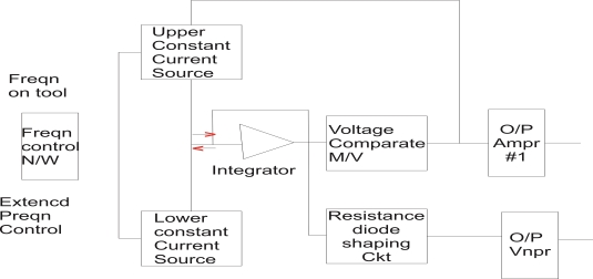
The function generator is an instrument which generates different types of wave formThe most required common wave forms are sine wave, saw tooth wave, triangle wave, square wave and these various outputs of the generator are available simultaneously. The purpose of providing simultaneously waves is fulfilled by the function generator In function generator the o/p waveform can be generated at a desired freqn in range from few hertz to several kilohertz. In the function generator the freqn is controlled which drives the integrator .The freqn controlled vtg is used to regulate two current source namely upper current source and lower current source.The upper current source supplies constant current to an integrator. The o/p vtg of integrator then increases linearly with time.If the current charging the capacitor increases or decreases the slope of o/p vtg increases or decreases respectively. Hence this controls freqn.
|
Block diagram of function generator
- The voltage comparator multi vibrator circuit changes the state of the n/w when the o/p vtg of integrator equals the maximum predetermined upper level.
- Because of this change in state the upper current source is removes and the lower current source is switched on
- This lower current source supplies opposite current to the integrator or ckt. The o/p of integrator decreases linearly with time when this o/p vtg equals maximum predetermine upper level on –ve side the comparator multi vibrator again changes the condition of the n/w by switching off the lower current source and switching on the upper current source
- The o/p vtg of the integrator has triangular wave form
- The freqn of this triangular wave form is determined by the upper current source and lower current source
- To get square wave the o/p of the integrator is passed through comparator.
- The vtg comparator delivers square wave o/p vtg of same freqn as that of i/p triangular wave form
- The sine wave is derived from triangular wave. The triangular wave is synthesised in to sine wave using diode resistance n/w in this shaper ckt , the slope of triangular wave is changed as it amplitude changes. This result in a sine wave with less than 1% distortion
- The two o/p amplifiers provide two simultaneous individually selected o/p of any of the wave form functions.
Application :
- it is used to generate different types of wave form simultaneous such as sine wave, square wave, triangular wave & saw tooth wave at a desired freqn from few hertz to several kilohertz.
- it is used to test bandwidth of audio freqnampɤ using square wave testing method
- it can be used in trouble shooting of various Analogas well as digital instruments.
- it is most extensively used as signal source for radio receiver alignment procedure.
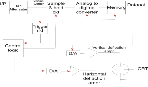
The digital storage oscilloscope replace the unreliable storage method used in Analogstorage scopes with the digital storage with the help of memory.The memory can store data as long as required without degradation. It also allows the complex processing of the signal by the high speed digital signal processing ckts.In this digital storage oscilloscope the wave form to be stored is digitised and then stored in a digital memory.The conventional cathode ray tube is used in this oscilloscope hence the cost is less the power to be applied to memory is small and can be supplied by small battery due to this the stored image can be display indefinitely as long as power is supplied to memory. Once the wave form digitised the it can be further loaded in to analysed in detail.
|
Block diagram
As done in all the oscilloscope the i/p signal is applied to the ampɤ and attenuator section the oscilloscope uses same type of ampɤ and attenuator cktry as used in the conventional oscilloscopeThe attenuator signal is then applied to the vertical ampɤ .The vertical i/p after + passing through the vertical ampɤ is digitised by an Analogto digital converter (A/D convertor) to create a data set that is stored in the memory .The data set is processed by the microprocessor and then send to the display. The main requirement of A/D convertor in the also is it speed. The digitising the Analogi/p signal means taking samples at periodic intervals of the i/p signal. The rate of sampling should be at least twice as fast as the highest freqn present in the i/p signal according to sampling theorem. The total digital memory storage capacity is 4096 for a signal channel 2048 for two channel each and 1024 for four channels each the sampling rate and memory size are selected depending upon the duration and the w/f to be recorded.Once the i/p signal is samples the A/D converter digitise it the signal is then captured in the memory.Once it is stored in the memory many manipulation are possible as memory can be read out without being erased
Advantages :
- It is easier to operate and has more capability
- The storage time is 0
- The display flexibility is available. The number of traces that can be stored and recalled depends an the site of the memory
- The cursor measurement is possible
- The characters can be displayed on screen along with the wave form which can indicate wave form information such as minimum, maximum, freqn , amplitude etc.
- The X-Y plots, B-H curve, p-v diagrams can be displayed
- Keeping the records is possible by transmitting the data to computer system where the further processing is possible
- Signal processing is possible which includes translating the raw data into finished information computing parameters of a captured signal like ɤ.m.s. value, energy stored etc.
- Brighter and bigger display with colour to distinguish multiple traces.
- The built in interfaces such as Rs 232 serial port, cento nix parallel , IEEE 488 bas are available
Application :
- Measurement of various a.c and d.c parameters such as current , vtgetc
- Measurement of various parameters of alternating signal such as ɤ.m.s., average, crest factor duty cycle etc.
- Measurement of freqn, time period, phase, phase difference for periodic and nonperiodic wave forms
- The transient parameters of fast changing waveform such as overshoot, rise time, fall time etc, can be measured
- Mathematical operations such as addition, subtraction integration etc. of various waveform can be obtained
- Used to measure slow moving parameters such as temperature of the day
- The operation such as FFT, DPT, IFT etc. can be performed
- The parameters like inductance, capacitance, impedance etc. also can be measured
- The characteristics various components such as V-I characteristics of diodes, transistor etc. can be obtained.
- For component testing and troubleshooting as the transients can be captured and stored
|
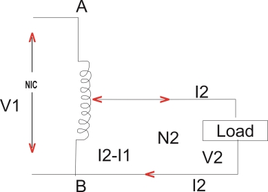
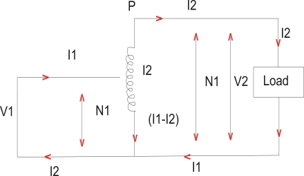
- An Autotransformer is a special type of transformer such that a part of the winding is common to both primary as well as secondary
- It has only winding wound on a laminated magnetic care. With the help of Autotransformer the voltage can be stepped down or can be stepped up also to any desired value
|
Fig A
Step down
|
Fig B
Step Up
- Fig A shows the step down transformer. AB acts as a primary winding while part of the primary winding BC acts as a secondary winding. The position of C called as % tapping point can be selected as per the requirement of the secondary vtg
- Fig B shows the step up a autotransformer where QS acts as a secondary winding
- The operating principle of the autotransformer is same as that of two winding transformer
- The current in the portion CB ie secondary in case of step down autotransformer is the vector difference Df
 2&
2& 1 while the current in the portion QS ie primary in case of step up autotransformer is the vector difference of
  2&
2& 1
1 - Neglecting the losses, the leakage reactance and the magnetising current we can write the transformation ratio of the autotransformer as
 =
=  =
= 
- Due to the use of single winding compared to normal teo winding transformer for the same capacity and vtg ratio there is substantial saving in copper in autotransformer.
- Copper required is very less
- The efficiency is higher compared to two winding transformer
- The size and hence cost is less compared to two winding transformer
- The copper losses
 2R are less
Limitation :
- Law impedance hence high short ckt current for short ckt on secondary side
- If a section of winding common to primary and secondary is opened, full primary and secondary which is risky in case of high vtg levels
Applications :
- For interconnecting systems which are operating roughly at same vtg
- For starting rotating machines like induction motors, synchronous motors
- To give a small boost to a distribution cable to current for the vtg drop
- As a furnace transformer for getting required supply vtg
- As a various to very thevtg to the load smoothly from zero to the rated value. Such various are commonly used for dimming the lights in cinema halls hence the various are also called dimmerstats
The D’ Arsonval Movement is basically a monoring action used as a basic principle of operation of various analog instruments such as voltmeters a m meters and ohm meters.In this movement there is a coil carrying current to be measure which is suspended between the poles of a permanent magnet A coil is moving coil whose movement is restrained by the springs.The flux produced by current carrying coil interacts with the flux of the permanent magnet and experiences a torque proportional to the current through the coil. When the current is interrupted the magnetic field produced by the coil collapses and coil returns to zero position due to the restraining springs. This movement of the coil is called D’ Arsonval movement. It is also called permanent magnet moving coil (PMMC) galvanometer. The basic D’ Arsonval movement has two important specifications
Im : full scale deflection current of the movement
Rm : Internal resistance of the coil………………………in the movement
Analog Ammeter :
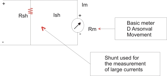
The coil used in the basic D’ Arsonval movement is very small and light due to which it can carry ver small currents for the measurement of large currents the major part of the current is bypassed using a resistance called in the basic movement. The shunt is commented in parallels with the basic meter.
Analog Motor
Multirangs Analog Ammeter :
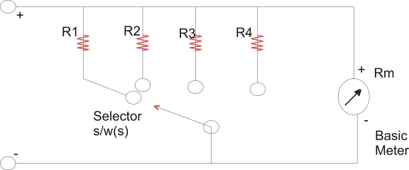
The range of the basic d.c ammeter can be extended by using number of shunts and a selector switch such a meter is called multirange ammeter
|
Multirange ammeter
The range of the basic d.c ammeter can be extended by using number of shunts R selected switch.R1,R2,R3 and R4 are four shunts when connected in parallel with the meter they can give four different ranges  1,
1, 2,
2, 3 and
3 and 4.The selector switch ‘S’ is multi position switch having low contact resistance and high current carrying capacity the high current break type switch is used for the range changing
|
Requirement of shunt :
- The temperature coefficient of shunt and the meter should be low and should be as equal as possible
- The shunt resistance should be stable and constant with time
- The shunt resistance should not carry currents which will cause excessive temperature rise
- Due to the soldering the values of resistance should not be changed
- The resistance should have low thermal electromotive force with copper
Precautions to be taken while using an ammeter :
- As the ammeter resistance is very low it should never be connected across any source of e.mf. always connect an ammeter in series with the load
- The polarities must be observed correctly the opposite polarities deflect the pointer in opposite direction against the mechanical stop and this may damage the pointer
- While using multirange ammeter first use the highest current range and there decrease the current rang until sufficient deflection is obtained so to increase the accuracy finally select the range which will give the reading near fail scale deflection
Analog Voltmeter
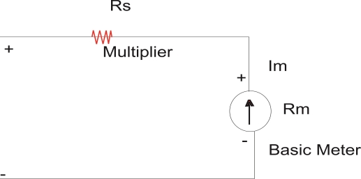
The basic d.c voltmeter is nothing but a PMMC D’ Arsonoval galvanometer .The resistance is required to be connected in series with the basic meter to use it as a voltmeter this series resistance is called a multiplier. The main function of the multiplier is to limit the current through the basic meter so that the meter current does not exceed the full scale deflection value The voltmeter measures the vtg across the two points of a circuit or a vtg across a ckt component. The voltmeter must be connected across the two point or a component to measure the potential difference with the proper polarity
|
Basic D.C Voltmeters
Multirange Voltmeter :
|
- The range of the basic d.c voltmeter can be extended by using number of multipliers and a selector switch such a meter is called multirange voltmeters
- The R1,R2,R3, R4 are the four series multipliers
- The multipliers are connected in a series string. The connections are brought out from the unction of the resistance. The selector switch is used to select the required vtg range
- Their resistance should not change with time
- The change in their resistance with temperature should be small
- They should be non inductively wound for a.c meters
Precautions to be taken while using a voltmeter :
- The voltmeter resistance is very high and it shoud always be connected across the circuit or component whose vtg is to be measured
- The polarity must be observed correctly. The wrong polarities deflect the pointer in the opposite direction again the mechanical stop & thismay damage the pointer
- Whileusing the multirange voltmeter first use the highest range them decrease the vtg range until the sufficient deflection is obtained
- Take care of the loading effect
Power Scope :
- The power scope has almost unlimited range of application in the power control field and other high vtg areas its features are wide range of measurement capability compact design light weight and high degrees of operator and equipment safety
- The i/p signal is attenuated by a factor of 20 by the i/p attenuator. The basic amplifier attenuator provides a sensitivity of50 mv/cm it is chanedto 100 mv/cm& 200 mv/cm by the gain switching further reduction in sensitivity is provided by the differential compensated attenuators.
Reference
1. “Digital Fundamentals” by Thomas. L. Floyd, 11th Edition, Pearson
2. “Mobile Communication” by J. Schiller, 2nd Edition, Pearson
3. “Sensors Handbook”, by S. Soloman, 2nd Edition.
