Unit 5
Sensors
Definition of a sensor
A sensor is a device which detects one form of energy and produces corresponding electrical signal.
Definition of a transducer
A transducer is a device that converts one form of energy into another form of energy.
Thus sensor is a type of transducer.
The sensors are classified based upon various aspects as follows,
A] Based upon transduction Principle –
1. Resistive sensors–
The output of resistive sensors is change in resistance corresponding to change in measurand.
Examples–strain gauge, resistance temperature detector ( RTD ), Thermistor
2. Capacitive sensors–The output of capacitive sensor is change in capacitance corresponding to change in measurand.
3. Inductive sensors–The output of inductive sensor is change in inductance corresponding to change in measurand.
Examples–Linear variable differential transformer ( L.V.D.T. )
4. Piezoelectric sensor –
It converts pressure signal into electrical signal.
5. Thermoelectric sensor –
It converts thermal energy into voltage signal.
Examples– Thermocouple
6. Photovoltaic sensor / Photoelectric sensor –
It has change in electrical properties due to incident light.
Examples – solar cell, LDR, photo diode
1. Active sensor
Active sensor is a sensor which does not require any external energy to generate voltage / current output upon applying input measurand.
Examples – Thermocouple, Piezo electric sensor, solar cell, tachogeneras.
2. Passive sensor
Passive sensor is a sensor which requires external energy ( auxillary power supply ) to generate voltage / current output upon applying input measurand.
Examples -R.T.D, strain gauge, L.V.D.T., L.D.R.
1. Primary sensor
The sensor which accepts measurand as input and converts it into another quantity corresponding to input is called as primary sensor.
Examples – LVDT for displacement measurement, strain gauge for pressure measurement
2. Secondary sensor
The sensor which accepts output of primary sensor as input and converts it into another quantity is called as secondary sensor.
Example – LVDT for pressure measurement.
Based on the form of output –
1. Analog sensors
The output of analog sensors is analog in form.
Examples – LVDT, strain gauge, thermocouple
2. Digital sensors
The output of digital sensors is digital code form.
Examples – Rotary and absolute encoders, stroboscope, proximity switches.
Motion sensors are used to sense / measure the motion related parameters like displacement, velocity, acceleration sensors are available for linear as well as rotary motion
Linear variable differential transformer ( LVDT ) –
LVDT is widely used sensor for the measurement of linear displacement. It is a transformer with one primary winding and two secondary windings. It works on the principle of voltage transformer ( mutual induction ).
Construction of LVDT :
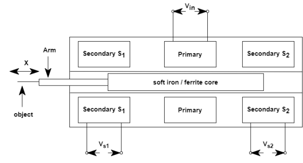
The figure below shows construction of LVDT.
|
LVDT has a primary and two secondary windings S1 and S2 wound on cylindrical forms. Both secondary windings have equal turns and they are identically placed on the either sides of primary. The soft iron / ferrite core is placed inside inside the former. The primary winding is fed through a.c excitation source with 1-3 KHz frequency. The object whose displacement is to be measured is connected to core through arm. The entire assembly is enclosed in a stainless steel body with electromagnetic shielding.
Working of LVDT :
The two secondaries of LVDT are connected in series opposition as shown in Figure below.
|
The primary of LVDT is fed by a.c excitation. Then voltage is transformed to secondaries due to mutual inductance between primary and secondary windings. The voltages induced in S1 and S2 are,
S1 = M1 di / dt
S2 = M2 di / dt
The mutual inductances M1 and M2 depend on core position. As the two secondaries are connected in series opposition, the output voltage is,
Vo = VS1 – VS2 = ( M1 – M2 ) di / dt
Vo α( M1– M2 )
The net mutual inductance M1 – M2 changes with core position. When the core is at centre, M1 = M2 and net voltage is zero. This is referred as null position. Now as core moves towards S1, es1 becomes greater than es2 and net voltage is positive. Similarly when core moves towards S2, es2 becomes greater than es1 and net voltage is negative ( with 180o phase shift ). Thus as the object moves, corresponding voltage with polarity is available at the output.
The input – output characteristic curve of LVDT is shown below.
|
The actual characteristics differ from ideal characteristics due to harmonics in input excitation, stray capacitance coupling between primary and secondaries, magnetic saturation. Due to these reasons we get residual ( null ) voltage and limited linear range.
Accelerometer
It is a sensor used for measurement of acceleration. It is also used for measurement of vibration, shock. The basic accelerometer sensor is mechanical system with mass, damper and spring. Such arrangement is known as selsmic instrument.
Construction :
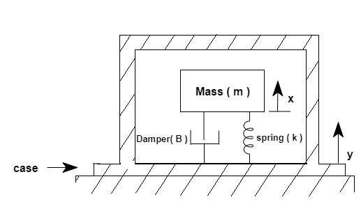
The construction of accelerometer is as shown below.
|
The accelerometer consists of a mass, damper and spring as shown figure. The mass is suspended freely and is connected to casing through damper and spring. The mass – damper – spring assembly is enclosed by a casing.
Working
Due to application of force the acceleration takes place. Hence mass – damper – spring experiences a displacement x and the casing experiences a displacement y. Then the relative displacement ( absolute displacement ) is x – y. The acceleration is directly proportional to the displacement with following relation.
X / y = 1 / Wn2 ejφ / ( 1–β2 )2 + ( 2ξβ )2
Where Wn = k / m k - > spring stiffness constant
M - > Mass
ξ = β / 2km β - > Damper constant
β = W / Wn W - > Frequency of force
φ = - tan-1 2ξβ / ( 1–β2 )
Thus by measuring x with displacement sensor attached to mass and knowing all constants ( K, M , B ) the acceleration can be measured.
The sensors that change their output with change in temperature are temperature sensors.
Examples – Thermocouple, RTD, thermistor, pyrometers.
Thermocouple
It is the active temperature sensor which generates voltage proportional to applied temperature.
Principle
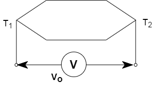
If two dissimilar pure metals are joined together at each end to form a loop with two junctions and a temperature difference exists between two junctions then a thermo – e.m.f( voltage ) proportional to temperature difference is generated.
|
Vo ∝( T2– T1 )
Vo = c [ T2 – T1 ]
Where C is sensitivity of thermocouple in mV / oC or µV / oC
The above principle is known as seeback effect.
Thus by measuring output voltage across the junction the temperature can be determined.
Construction
The two dissimilar metals are joined together to form two junctions. The thermocouple junctions are placed in protective casing of stainless steel and output terminals are made for voltage measurement.
Working
One of the thermocouple junction is kept as reference junction ( J1 ) and other is considered as measuring junction ( J2 ). The reference junction is kept at ambient temperature T1 and the measuring junction is exposed to chamber whose temperature is to be measured. Then due to temperature difference the thermo e.m.f. Vo is generated.
We have,
Vo = C [ T2 – T1 ]
T2 = Vo / C + T1
For better accuracy, the reference junction is kept in ice bath to have T1 = 0. Then
T2 = Vo / C
This eliminates error due to fluctuation in ambient temperature.
The commonly used material for thermocouple are
Type Wire Material Range Sensitivity
+ve - ve( oC ) ( µV / oC )
S Platinum 90% Platinum 0 – 1450 oC 5 - 12
10% Rhodium
R Platinum87% Platinum 0 – 1482 oC 5 – 12
13% Rhodium
T Copper Constantan - 253 to 371oC 15 – 60
J Iron Constantan - 116 to 760 oC 45 – 57
K ChromelAlumel - 200 to 1200 oC 40 – 55
E Chromel Constantan - 150 to 1260 oC 40 – 50
K type T / C is widely used due to linear characteristics and higher sensitivity.
Thermistors
Thermistors are temperature sensitive resistors. Thermistors are manufactured using semiconductors.
Principle
The resistance of the thermistor’schanges with the change in temperature.
The relation between resistance of thermistor and temperature is,
β( 1 / T – 1 / To )
RT = Roe
Where, RT - > Resistance at T oC
Ro - > Resistance at TooC
β - > Material constant
Thermistors are available in two types as
1>. Negative temperature coefficient ( NTC ) thermistors
2>. Positive temperature coefficient ( PTC ) thermistors
The resistance of NTC thermistors decrease with increase in temperature while resistance of PTC thermistor increase with increase in temperature.
The characteristic curves of PTC and NTC thermistors are as follows,
|
Due nonlinear characteristics PTC thermistors are less preferred over NTC thermistors.
Resistance Temperature Detector ( RTD ) –
Principle –
The electrical resistance of metals vary with change in temperature. The relation is given by,
RT = Ro ( 1 + αoΔT )
Where, RT - > Resistance at T oC
Ro - > Resistance at 0 oC
αo - > Resistance temperature coefficient at 0 oc
ΔT - > Temperature Difference ( T– O = T )
Construction –
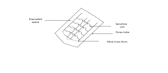
The figure below shows typical wire wound RTD arrangement.
|
The temperature sensitive coil is wound around the mica cross framework. The coil should be strain free. This assembly is placed in evacuated pyrex tube. The terminals are made available for resistance measurement.
Working –
The RTD is placed inside the chamber whose temp is to be measured. Due to change in temperature, the resistance of coil gets changed by measuring the resistance, temp can be defined.
We have,
RT = Ro ( 1 + αo T ) = Ro + αo Ro T
T = RT – Ro / αo Ro
Generallu, RTD PT 100 is used. It is made up of platinum with
αo = 0.00392 Ω / Ω / oC
and has Ro = 100 Ω.
The input – output characteristics are as follows
|
Measurement System
In temperature measurement system with RTD, instead of measuring resistance, the bridge arrangement is used to get proportionate voltage signal at output. The bridge arrangement is as shown below,
In this arrangement change in resistance of RTD causes voltage at output which is proportional to temperature.
|
RTD is used for temperature range – 2000C to 650 0C.
Semiconductors have been used for sensors since the middle of the 20th century and have been involved in some of the most advanced physical experiments and discoveries. They have helped to uncover the mechanism of radiation-induced damage as well as identifying many nuclear physics principles.
Miniaturized smart sensors based on semiconductors make use of novel materials and new processes to replace the cumbersome and costly conventional sensors. These are used for several applications, including navigation systems, optical devices, and motion sensors, as well as health monitors.
Many types of semiconductor temperature sensors are available, and are classified into five categories:
- Voltage output - linear output, low output impedance.
- Current output - constant current regulator displaying high impedance.
- Digital output - both sensor and analog-to-digital converter integrated on one chip, typically specific to microprocessor chips rather than measuring devices.
- Resistance output - exploits temperature vs. bulk resistance properties of semiconductors to provide more stable sensors, but may heat up which can be hazardous.
- Simple diodes - the least expensive, but require two-point calibration and stable current input for good results
Use: Semiconductor Detectors
Micro strips of silicon are used extensively in particle physics experiments, because of the high resolution and efficiency they offer. They are durable and inexpensive, with small magnetic effects. The detector material which is present between a pair of electrodes is affected by the radiation, setting free a variable number of charge carriers. This helps measure the ionizing radiation incident on the strip.
Advanced detectors will help analyze the type of radiation, by their alpha, beta and gamma nature, as well as by activation analysis.
The optical sensors are sensitive to light. The electrical properties of these sensors change with the intensity of light falling on them. The following optical sensors are commonly used.

 1. Photo diode
2. Photo transistor
3. Photo voltaic cell
4. Photo multiplier tube
5. Light dependent resistor ( LDR )
Light dependent resistor ( LDR )
It is a device whose resistance depends on the intensity of light falling on it. It is also called as photo resistor.
Principle
The resistivity of LDR decreases with increase in light intensity.
LDR is represented by a symbol
|
Construction
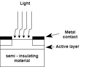
The constructional details of LDR are as shown in figure below.
|
The LDR has a lightly doped active semiconductor region deposited insulating material. The metal contact is placed on the active layer. To have relatively large area that is exposed to light, the pattern is cut in the metallisation on the surface of the active area which allows light to pass through.
Working
LDR is made up of semiconductor material with high resistance. It has high resistance because there are very less free electrons and majority of electrons are locked into the crystal lattice structure. When the light falls on the LDR, the photons are absorbed by the active layer region. The energy of absoebed photons is transferred to electrons locked into the crystal lattice. This energy makes the electrons free to move which allows conduction of electricity. Due to this action, the resistivity of LDR falls. The typical characteristics of LDR are as shown below.
|
The resistance of LDR when no light falls on it is called as dark resistance. The typical value of dark resistance is in MΩ. In day light the resistance of LDR falls in KΩ.
Typical values can be in the range,
Dark resistance – 20 MΩ.
Day light resistance – 5 KΩ.
Strain gauge
Strain gauge is an elastic resistive transducer which converts mechanical elongation and compression ( strain ) into change in resistance. Strain gauge is widely used for the measurement of strain, pressure, force and weight.
Principle
Resistance of any conductor depends on its resistivity, length and cross sectional area. Hence if there is change in length or cross sectional area due to compression or elongation, resistance gets changed. Also, in elastic material, upon application of stress ( pressure ), proportionate strain takes place in material and resistance gets changed.
The resistance is given by,
R = ϱl / A
ϱ - > resistivity
l - > length
A - > cross sectional area
Now when strain gauge undergoes tension or compression its dimensions are changed as shown below.
These changes in l and D causes change in resistance as, R = ϱl / A
= A (ϱ d l ) + A l d ϱ – ϱldA / A2 = A (ϱ d l + l d ϱ ) – ϱldA / A2 dR / R = [ A ϱ d l + A l d ϱ – ϱldA / A2 ] / [ϱl / A ] dR / R = A2 ϱ dl + A2 l d ϱ - A ϱ l dA / A2 ϱl = dl / l + d ϱ / ϱ – dA / A Let the conductor has circular cross section. Then, A = ∏D2 / 4 dA = 2∏DdD / 4 = ∏DdD / 2 dA / A = ∏DdD / 2 / ∏D2 / 4 = 2dD / D dR / R = dl / l + dϱ / ϱ – 2dD / D Now axial strain, ξa = dl / l Lateral strain, ξL = - dD / D dR / R = d ϱ / ϱ + ξa + 2ξL
The Poisson’s ratio is defined as, V = ξL / ξa dR / R = d ϱ / ϱ + ξa ( 1 + 2V ) dϱ / ϱ ≈ 0 dR / R = ξa ( 1 + 2V ) The sensitivity ( gauge factor ) is defined as, S = dR/R / dl/l = ξa( 1 + 2V ) / ξa = 1 + 2V = G.F. And dR / R = ξa( G.F. ) or ξa = 1 / G.F. dR / R Thus if change in resistance is measured, strain can be determined. Strain gauge can be used for pressure measurement as well. The pressure applied to elastic material is directly proportional to strain and hence change in resistance is related to applied pressure as, P ≡ K / G.F. dR / R Where k is constant of proportionality between pressure and strain. In general, the pressure measuring system using strain gauge uses bridge for converting change in resistance into corresponding voltage. The bridge arrangement is as shown below.
|
Load Cell
Load cell is a sensor used for free and weight measurement. It uses strain gauge as sensing element. Strain gauge produces change in resistance proportional to applied pressure. The relation between force and pressure is,
P = F / A
P ∝F
Hence strain gauge produces change in resistance proportional to applied force.
The load cell is generally used in two configurations given below
1. Column type load cell configuration
2. Cantiliver beam cell configuration
Mechanical Pressure Sensors
The mechanical pressure sensors are formed of elastic elements. The different elastic pressure sensors are
1. Bourdon tube
2. Bellows
3. Diaphragm
Bourdon tube
The Bourdon tube is the most commonly used elastic pressure sensor in mechanical dial gauges. The bourdon tubes are available in C – shape, spiral shape, twisted tube configuration and helical shape.
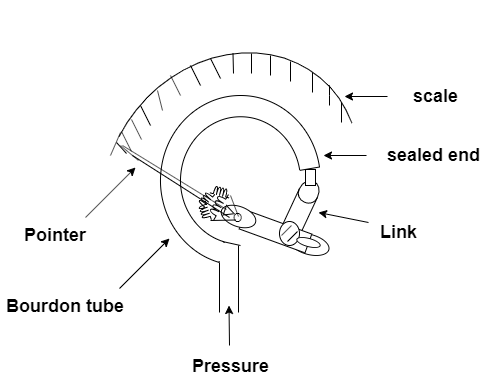
C – shaped tube is used in dial gauges. The C – shaped bourdon tubes are made out of an elliptically flattened tube bent in such a way that produces C shape. One end of tube is sealed and the other end is exposed to pressure. The figure below shows is construction of pressure gauge with bourdon tube.
|
Working
When the pressure is applied at open end of bourdon tube, the tube bends to straighten. This causes movement of sealed end of tube. This movement is connected to pointer through the mechanical linkage. Thus pointer moves and shows pressure on calibrated scale.
Bellows
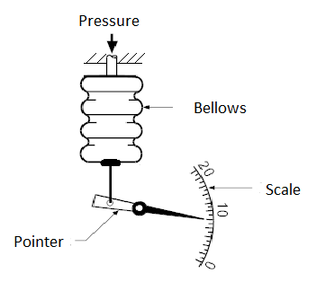
A metallic bellow is formed from a series of circular parts resembled in folds. These circular parts are joined in such a way that they are expanded or contracted axially by change in applied pressure. The figure below shows construction of pressure gauge using bellows.
|
Working –
- When pressure is applied to bellows it expands and this movement is used to move the pointer on calibrated scale.
- The bellows are also used in differential mode to measure differential pressure. In this case both sides of bellows have open ends for applying the pressure.
Diaphragms –
Diaphragms are flexible circular disks either flat or corrugated. The figure below explains working principle of diaphragm.
|
Example – RTD inserted in an oven has resistance 160 Ω. Its resistance at 0 oC is 100 Ω and its resistance temperature coefficient is 0.00392 Ω/ oC.
Soln – Given data,
RT = 160 Ω
Ro = 100 Ω
α = 0.00392 Ω/ oC
We have,
RT = Ro ( 1 + αo T )
160 = 100 ( 1 + 0.00392 T )
1.6 = 1 + 0.00392
T = 0.6 / 0.00392 = 153.0612 oC
Thermistor –
RT = Ro e β( 1 / T –1 / To )
Where, RT = Resistance of thermistor at T oC
Ro = Resistance at To oC
β = Material constant
Example– Thermistor with material constant 100 is placed in an oven, has resistance 5 KΩ. Its resistance at 25 oC is 10000 Ω. Determine temperature of oven.
Soln – Given data,
RT = 5000 Ω
Ro = 10000 Ω
To = 25 oC, β = 100
We have,
RT = Ro e β( 1 / T – 1 / To )
5000 = 10000 e100( 1/T – 1 / 25 )
0.5 = e100 / T – 4
Ln 0.5 = 100/T – 4
100 / T = 4 – 0.6931
T = 100 / 3.3069 = 30.29 oC
Strain Gauge –
dR / R = ( 1 + 2V ) ξa = G.F. ( ξa ) = ( G.F. ) dl / l
where, dR = change in resistance
R = Resistance when no stress is applied
ξa = Axial strain = dl / l
V = Possion’s ratio
G.F. = Gauge factor = 1 + 2 V
Example – A strain gauge with gauge factor of 4 has resistance of 120 Ω when unstrained. If strain gauge undergoes change in length from 0.25 mm to 0.255 mm. Determine new resistance.
Soln Given data,
G.F. = 4, R = 120 Ω, l = 0.25 mm, dl = 0.255 – 0.25 = 0.005 mm
We have,
dR / R = ( G.F. )Dl / l
dR / 120 = 4( 0.005 / 0.25 )
dR = 120 ( 4 )( 0.002 ) = 9.6 Ω
Rnew = 120 + 9.6 = 129.6 Ω
Biosensors are analytical devices that convert a biological response into an electrical signal. Quintessentially biosensors must be highly specific, independent of physical parameters such as pH and temperature and should be reusable.
Fabrication of biosensors, its materials, transducing devices, and immobilization methods requires multidisciplinary research in chemistry, biology, and engineering. The materials used in biosensors are categorized into three groups based on their mechanisms: biocatalytic group comprising enzymes, bioaffinity group including antibodies and nucleic acids, and microbe based containing microorganisms.
TYPES:
- enzyme-based,
- tissue-based,
- immune sensors,
- DNA biosensors,
- thermal and
- piezo electric biosensors.
Immuno sensors were established on the fact that antibodies have high affinity towards their respective antigens, i.e. the antibodies specifically bind to pathogens or toxins, or interact with components of the host's immune system.
The DNA biosensors were devised on the property that single-strand nucleic acid molecule is able to recognize and bind to its complementary strand in a sample. The interaction is due to the formation of stable hydrogen bonds between the two nucleic acid strands.
Magnetic biosensors: miniaturized biosensors detecting magnetic micro- and nano particles in micro fluidic channels using the magneto resistance effect have great potential in terms of sensitivity and size
Thermal biosensors or calorimetric biosensors are developed by assimilating biosensor materials as mentioned before into a physical transducer.
Piezoelectric biosensors are of two types: the quartz crystal microbalance and the surface acoustic wave device. They are based on the measurement of changes in resonance frequency of a piezoelectric crystal due to mass changes on the crystal structure.
Optical biosensors consist of a light source, as well as numerous optical components to generate a light beam with specific characteristics and to beeline this light to a modulating agent, a modified sensing head along with a photo detector.
References:
1. “Electronics Devices” by Thomas. L. Floyd, 9th Edition, Pearson (Unit I, II)
2. “Modern Digital Electronics” by R.P. Jain, 4th Edition, Tata McGraw Hill (Unit III)
3. “Electronic Instrumentation” by H.S. Kalsi, 3rd Edition, Tata McGraw Hill (Unit IV)
4. “Sensors and Transducers” by D. Patrnabis, 2nd Edition, PHI (Unit V)
