Unit – 6
Communication Systems
Introduction to Electronic Communications
The telegraph was invented in 1844. [ Morse Patent ]
The telephone was invented in 1876. [ Bell Patent ]
In 1887 radio was invented [ Hertz invent ]
In 1895 Marconi demonstrates wireless telegraphy.
1923 : Television is invented.
1948 : Transistor is invented.
1954 :Color television broadcasting begins
1969 : The internet is invented.
1983 : First cellular telephone system becomes operational.
1989 : GPS is used for commercial and personal applications.
1989 : www is invented.
1998 : The first commercial use of digital / high definition television takes place.
Simplex is one way communication.
Duplex is two way communication.
Telegraph used Morse code whereas radio telegraphy used an international code of dots and dashes.
The most commonly used digital code in communications is the American Standard code for information interchange [ ASCII ].
Putting the original voice, video or digital signals directly into the medium is referred to as baseband transmission.
Eg : telephone and intercom communications systems. In some computer network ie digital signals are applied directly to coaxial cables for transmission to another computer.
To transmit baseband signals by radio, modulation techniques must be used. Techniques using modulation are referred to as broadband.
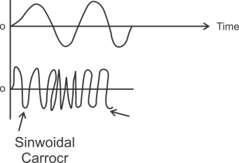
Modulation is the process of having a baseband voice, video or digital signal modify another higher freqn signal called the carrier.
In AM, the baseband signal varies the amplitude of the higher freqn carrier signal.

In FM the basband signal varies the freqn of the carrier.
|
Shifting the phase of the carrier in accordance with the i/p modulating signal produces phase modulation ( PM ). Phase modulation produces FM so a PM signal looks like the FM.
Electromagnetic signals are also referred to as radio freqn( Rf ) waves.
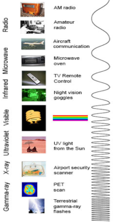
The electromagnetic spectrum used in electronic communication
The ionosphere refracts radio waves making long distance communication possible for some frequencies at certain times.
The visible range is approximately 8000 Ao( red ) to 4000 Ao ( violet ).
Light wavelengths are usually expressed interms of angstroms ( Ao ).
An angstrom is one ten thousandth of a micron.
Light is widely used for various kinds of communications. The great advantage of light wave signals is that their very high frequency gives them the ability to handle a tremendous amount of information. That is the bandwidth of the baseband signals may be very wide.
Audio signals are not transmitted by electromagnetic waves because
1>. Antennas would be too long.
2>. Simultaneous transmission would interfere.
HF signals are also called sharewaves.
Freqn above 1 GHz are called microwave.
Any broadcasting audio signalsupto 5 KHz may be transmitted.
Government also established the Federal communication’s Commission [ FCC ] which is a regulatory body whose sole purpose is allocating spectrum space, issuing licences, setting standards & policing the airwaves.
The FCC controls all telephone & radio communications in this country & in general regulates all electromagnetic emissions.
The national telecommunications and information administration [ NTIA ] performs a similar function for government & military services.
|
Fig. 1 Block diagram of elements of communication (ref 3)
- Information Source
It produces a message that is analog in nature, i.e., the output of the information source is a continuous signal.
- Analog carrier source
Sine wave is used as a carrier signal which will help in analog modulation.
- Analog modulation
The carrier signal is superimposed with the message signal and then the modulated signal is obtained which is also analog in nature.
- Communication channel
The analog modulated signal is transmitted via the communication channel towards the receiver end after addition of the requisite power levels.
- Analog demodulation
At the receiver end, the incoming modulated signal is passed through an analog demodulation process which extracts the analog message signal. The analog message is then passed onto the final destination.
- Destination
The nature of signal starting from the information source till the final destination is analog.
1. Amplitude Modulation ( AM ) :- Amplitude ( A ) of the carrier signal is varied keeping it’s freqn& phase ( φ ) constant.
2. Frequency Modn( FM ) :-Freqn ( F ) of the carrier signal is varied keeping its amplitude ( A ) & Phase (φ ) constant.
3. Phase Modulation ( PM ) :- Phase (φ ) of the carrier signal is varied keeping its freqn ( F ) and amplitude ( A ) constant.
Necessity of Modulation :-
1. Antenna height reduces
2. Avoids mixing of signal
3. Increases the range of communication [ InKilometers]
4. Multiplexing of signals is possible
5. Improves quality of reception of signal.
|
Receiver :-The received signal is processed by the various ckts like preamplifier, mixer, oscillator, detector, demodulator, driver ampr and power ampr.
In telephone baseband communication :- Analog information transmitted through parallel two wires.
The bandwidth of 300Hz to 3400Hz is adequate for a telephone voice conversation, 15Hz to 20Hz for music and 5Hz bandwidth for a typical video signal.
Transmission Media :-
1. Guided :-Signals are transmitted via a physical and tangible guide betn the communicating points. These parallel wire, coaxial cable, wave guides and optical fiber.
2. Unguided :- Physically there is no direct physical connection betn points such as microwave & satellite links. Mobile phone also uses unguided transmission media.
|
Radio: Your radio captures radio waves emitted by radio stations, bringing your favorite tunes. Radio waves are also emitted by stars and gases in space.
Microwave: Microwave radiation will cook your popcorn in just a few minutes, but is also used by astronomers to learn about the structure of nearby galaxies.
Infrared: Night vision goggles pick up the infrared light emitted by our skin and objects with heat. In space, infrared light helps us map the dust between stars.
Visible: Our eyes detect visible light. Fireflies, light bulbs, and stars all emit visible light.
Ultraviolet: Ultraviolet radiation is emitted by the Sun and are the reason skin tans and burns. "Hot" objects in space emit UV radiation as well.
X-ray: A dentist uses X-rays to image your teeth, and airport security uses them to see through your bag. Hot gases in the Universe also emit X-rays.
Gamma ray: Doctors use gamma-ray imaging to see inside your body. The biggest gamma-ray generator of all is the Universe.
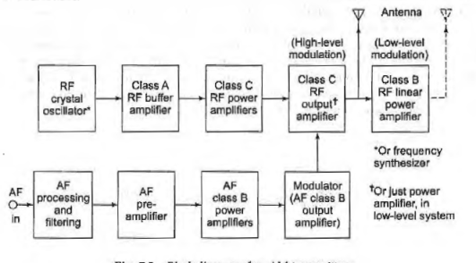
AM TRANSMITTER
- AM transmitter generates high power and its primary requirement is efficiency.
- Here, AM is produced is of very low power.
- Although the methods of generating AM described here relate to both applications and emphasis will be put on methods of generating high powers.
- In an AM transmitter, amplitude modulation can be generated at any point after the radio frequency source.
- Actually, even a crystal oscillator could be amplitude modulated, except that this would be an unnecessary interference with its frequency stability.
- lf the output stage in a transmitter is collector modulated in a low power transmitter, the system is called high level modulation.
- lf modulation is applied at any other point, including some other electrode of the output amplifier, then so called low level modulation is produced.
- Naturally, the end product of both systems is the same, but the transmitter circuit arrangements are different .
- The higher the level of modulation, the larger the audio power required to produce modulation.
- The higher-level system is a disadvantage in this regard.
- On the other hand, the output stage is modulated, each following stage must handle a sideband power as well as the carrier.
- All these subsequent amplifiers must have sufficient bandwidth for the sideband frequencies.
- Each of the systems have one great advantage i.e. low modulating power requirements in one case, and much more efficient RF amplification with simpler circuit design in the other.
- lt is found that a collector~modulated class C amplifier tends to have better efficiency, lower distortion and much better power-handling capabilities than a base-modulated amplifier. Because of these considerations, broadcast AM transmitters today almost invariably use high-level modulation.
|
Fig. AM Transmitter (ref 3)
AM Receiver :-
|
Fig. Superheterodyne AM receivers (ref 3)
- The signal is received by the RF amplifier which is a wideband class A amplifier whose resonant frequency response curve can be tuned from 540 kHz to 1650 kHz .
- The modulated signal is amplified and fed to the mixer stage which is a class C circuit capable of producing the sum, difference, and original frequencies, and which receives signals from two sources namely the RF amplifier and the local oscillator.
- The unmodulated signal from the local oscillator is further fed to the mixer where simultaneously it is mixed with the modulated signal received from the RF amplifier.
- The local oscillator (LO) is a tunable circuit with a tuning range that extends from 995 kHz to 2105 kHz.
- The output from the mixer circuit is then connected to the intermediate frequency amplifier (IF amp) which amplifies a narrow band of select frequencies (455 kHz± 3 kHz).
- In some receivers this class A circuit acts not only as an amplifier but also as a filter for unwanted frequencies which would interfere with the selected one.
- This new frequency contains the same modulated information as that transmitted from the source but at a frequency range lower than the standard broadcast band.
- This process helps to reduce the unwanted interference from outside sources.
- The signal is further rectified and filtered to eliminate one sideband and is finally amplified for listening.
F.M. Transmission :-
A signal is described by its amplitude freqn and phase. Frequency and phase constitute the angle.
In angle modulation the freqn or phase of carrier is varied according to the message / modulating signal.
The method of angle modulation in which freqn of carrier is varied is called freqn modulation ( FM ).
The method of angle modulation in which phase of carrier is varied is called phase modulation ( PM ).
FM is more popular than AM and is useful for high fidelity broadcasting of audio & other applications.
The Advantages of FM are :
1. It has better noise immunity
2. The performance of FM is better at low power
3. Transmission bandwidth is not affected by msg signal bandwidth.
The Disadvantages of FM are :
P.M. & F.M. are nonlinear modulation techniques. Hence the analysis of angle modulation is complex and we have to rely on approximate analysis.
Angle modulated signal theoretically has infinite bandwidth even for band limited signals. Hence we have talk about effective bandwidth. This effective bandwidth is much higher than that required in AM.
F.M. Reception :-
The FM receiver is also a super heterodyne receiver like AM. But following considerations are required for an FM receiver.
1. The operating frequency of FM is higher compared to AM.
2. Different detection or demodulation technique will be required for FM.
3. There will be need for amplitude limiting & de-emphasis in FM.
4. Different method of obtaining AGC is required.
Mixer Uses colpits &clapp oscillator for VHF range.
If ampr If = 10.7 MHz with BW 200 KHz gain low use two If stages to improve gain.
References
1. “Electronics Devices” by Thomas. L. Floyd, 9th Edition, Pearson (Unit I, II)
2. “Modern Digital Electronics” by R.P. Jain, 4th Edition, Tata McGraw Hill (Unit III)
3. “Electronic Instrumentation” by H.S. Kalsi, 3rd Edition, Tata McGraw Hill (Unit IV)
4. “Sensors and Transducers” by D. Patrnabis, 2nd Edition, PHI (Unit V)


