Unit – 1
Fundamental of engineering drawing
Engineering drawing is a two-dimensional representation of three dimensional objects. In general, it provides necessary information about the shape, size, surface quality, material, manufacturing process, etc., of the object. It is the graphic language from which a trained person can visualize objects.
Drawings prepared in one country may be utilised in any other country irrespective of the language spoken. Hence, engineering drawing is called the universal language of engineers. Any language to be communicative, should follow certain rules so that it conveys the same meaning to everyone. Similarly, drawing practice must follow certain rules, if it is to serve as a means of communication. For this purpose, Bureau of Indian Standards (BIS) adapted the International Standards on code of practice for drawing. The other foreign standards are: DIN of Germany, BS of Britain and ANSI of America.
Role of Engineering Drawing
The ability to read drawing is the most important requirement of all technical people in any profession.As compared to verbal or written description, this method is brief and clearer. Some of theapplications are: building drawing for civil engineers, machine drawing for mechanical engineers,circuit diagrams for electrical and electronics engineers, computer graphics for one and all.
The subject in general is designed to impart the following skills.
1. Ability to read and prepare engineering drawings.
2. Ability to make free - hand sketching of objects.
3. Power to imagine, analyze and communicate, and
4. Capacity to understand other subjects.
Introduction
Engineering drawings are prepared on standard size drawing sheets. The correct shape and sizeof the object can be visualized from the understanding of not only its views but also from thevarious types of lines used, dimensions, notes, scale etc. For uniformity, the drawings must bedrawn as per certain standard practice.
Drawing Sheet
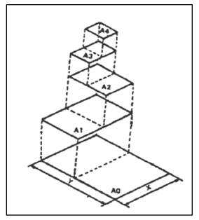
The standard drawing sheet sizes are arrived at on the basic Principal ofx: y = 1: and xy = 1 where x and yare the sides of the sheet. For example, A0, having a surfacearea of 1 Sq. m; x = 841 mm and y = 1189 mm. The successive sizes are obtained by either byhalving along the length ordoubling the width, the area being in the ratio 1: 2. Designation of sizesis given in Fig.l and their sizes are given in Table 1. For class work use of A2 size drawingsheet is preferred.
Table 1
Designation | Dimension, mm (Trimmed size) |
A0 | 841 × 1189 |
A1 | 594 × 841 |
A2 | 420 × 594 |
A3 | 297 × 420 |
A4 | 210 × 297 |
|
Figure 1
Title block
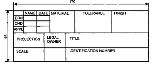
The title block should lie within the drawing space at the bottom right hand comer of the sheet.The title block can have a maximum length of 170 mm providing the following information.
1. Title of the drawing.
2. Drawing number.
3. Scale.
4. Symbol denoting the method of projection.
5. Name of the firm, and
6. Initials of staff who have designed, checked and approved.
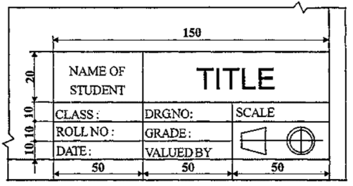
The title block used on shop floor and one suggested for student’s class work are shown inFig.2& Fig. 3.
|
Figure 2 Shop floor drawing sheet layout
|
Figure 3 Students class work
Drawing sheet layout
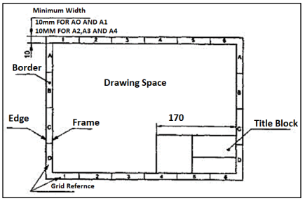
The layout of a drawing sheet used on the shop floor is shown in Fig.2.3a. The layout suggested tostudents is shown in Fig.2.3b.
|
Figure 4 General features of a drawing sheet
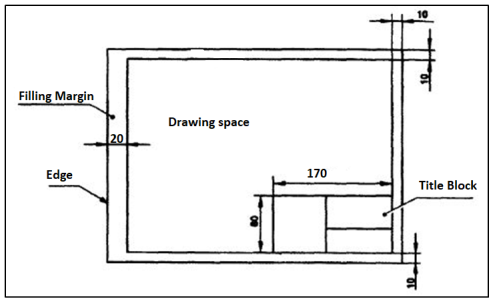
Figure 5 Layout of sheet for a class work
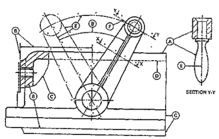
Just as in English textbook the correct words are used for making correct sentences; in EngineeringGraphics, the details of various objects are drawn by different types of lines. Each line has adefinite meaning and sense toconvey.
IS 10714 (Pint 20): 2001 (General principles of presentation on technical drawings) and SP 46:2003specify the following types oflines and their applications:
1. Visible Outlines, Visible Edges: (Continuous wide lines) The lines drawnto represent the visible outlines/ visible edges / surface boundary lines of objects should beoutstanding in appearance.
2. Dimension Lines: (Continuous narrow Lines) Dimension Lines are drawnto mark dimension.
3. Extension Lines: (Continuous narrow Lines)There are extended slightly beyond therespective dimension lines.
4. Construction Lines: (Continuous narrow Lines)Construction Lines are drawn forconstructing drawings and should not be erased aftercompletion of the drawing.
5. Hatching / Section Lines: (Continuous Narrow Lines)
Hatching Lines are drawn for the sectioned portion of an object. These are drawn inclinedat an angle of 45° to the axis or to the main outline of the section.
6. Guide Lines: (Continuous Narrow Lines)
Guide Lines are drawn for lettering and should not be erased after lettering.
7. Break Lines: (Continuous Narrow Freehand Lines)
Wavy continuous narrow line drawn freehand is used to represent break of an object.
8. Break Lines: (Continuous Narrow Lines with Zigzags)
Straight continuous arrow line with zigzags is used to represent break of an object.
9. Dashed Narrow Lines: (Dashed Narrow Lines)
Hidden edges / Hidden outlines of objects are shown by dashed lines of short dashes ofequal lengths of about 3 mm, spaced at equal distances of about 1 mm. the points of intersectionof these lines with the outlines / another hidden line should be clearly shown.
10. Center Lines: (Long-Dashed Dotted Narrow Lines)
Center Lines are drawn at the center of the drawings symmetrical about an axis or both theaxes. These are extended by a short distance beyond the outline of the drawing.
11. Cutting Plane Lines:
Cutting Plane Line is drawn to show the location of a cutting plane. It is long-dashed dottednarrow line, made wide at the ends, bends and change of direction. The direction of viewingis shown by means of arrows resting on the cutting plane line.
12. Border Lines
Border Lines are continuous wide lines of minimum thickness 0.7 mm.
|
Figure 6 Types of lines
Table 2 Types of lines and their applications
Line | Description | General application |
| Continuous thick or continuous wide | Visible outlines, visible edges, main representation in diagrams, maps; system lines |
| Continuous thin (narrow) (straight or curved) | Imaginary lines of intersection; grid, dimension. extension, projection, reference lines and hatching. |
| Continuous thin (narrow) freehand. | Limits of partial or interrupted views and sections, if the limit is not a chain thin line. |
| Continuous thin (narrow) with zigzags (straight) | Long break line |
| Dashed thick (wide) | Line showing permissible of surface treatment. |
| Dashed thin (narrow) | Hidden outline; hidden edges |
| Chain thin Long-dashed dotted (narrow) | Centre line; lines of symmetry; trajectories; pitch circle of gears, pitch circle of holes. |
| Chain thick or long - dashed (dotted) wide | Indication of lines or surfaces to which a special requirement applies. |
Line widths:
Line width means line thickness
Choose line widths according to the size of the drawing from the following range: 0.13,0.18,0.25, 0.35, 0.5, 0.7 and 1 mm.
Precedence of Lines
1. When a Visible Line coincide with a Hidden Line or Center Line, draw the Visible Line.Also, extend the Center Line beyond the outlines of the view.
2. When a Hidden Line coincides with a Center Line, draw the Hidden Line.
3. When a Visible Line coincides with a Cutting Plane, draw the Visible Line.
4. When a Center line coincides with a Cutting Plane, draw the Center Line and show the
Cutting Plane line outside the outlines of the view at the ends of the Center Line by thickdashes.
Dimensioning:
Drawing of a component, in addition to providing complete shape description, must also furnish information regarding the size description. These are provided through the distances between the surfaces, location of holes, nature of surface finish, type of material, etc. The expression of these features on a drawing, using lines, symbols, figures and notes is called dimensioning.
Principles of Dimensioning
Some of the basic principles of dimensioning are given below.
1. All dimensional information necessary to describe a component clearly and completely shallbe written directly on a drawing.
2. Each feature shall be dimensioned once only on a drawing, i.e., dimension marked in oneview need not be repeated in another view.
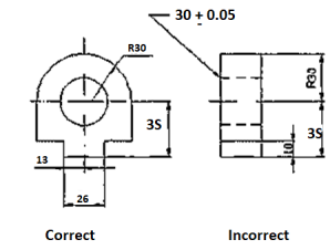
3. Dimension should be placed on the view where the shape is best seen (Fig.7)
4. As far as possible, dimensions should be expressed in one unit only preferably in millimeters,without showing the unit symbol (mm).
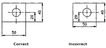
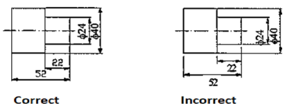
5. As far as possible dimensions should be placed outside the view (Fig. 8).
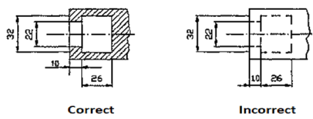
6. Dimensions should be taken from visible outlines rather than from hidden lines (Fig. 9).
|
Figure 7
|
Figure 8
|
Figure 9
7. No gap should be left between the feature and the start of the extension line (Fig.10).
|
Figure 10 Marking of Extension lines
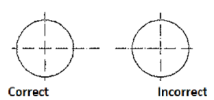
8. Crossing of center lines should be done by a long dash and not a short dash (Fig.11).
|
Figure 11 Crossing of Centre lines
Execution of dimensions:
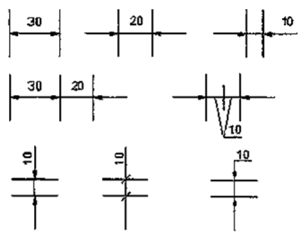
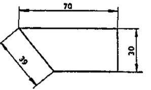
1. Projection and dimension lines should be drawn as thin continuous lines. Projection linesshould extend slightly beyond the respective dimension line.Projection lines should be drawnperpendicular to the feature being dimensioned. If the space for dimensioning is insufficient,the arrow heads may be reversed, and the adjacent arrow heads may be replaced by a dot(Fig.12). However, they may be drawn obliquely, but parallel to each other in special cases,such as on tapered feature (Fig.13).
|
Figure 12 Dimensioning in narrow spaces
|
Figure 13 Dimensioning a tapered feature
2. A leader line is a line referring to a feature (object, outline, dimension). Leader lines shouldbe inclined to the horizontal at an angle greater than 30°. Leader line should terminate,
(a) with a dot, if they end within the outline ofan object (Fig.2.21a).
(b) with an arrow head, if they end on outside of the object (Fig.2.21b).
(c) without a dot or arrow head, if they end on dimension line (Fig.2.21c).
|
Figure 14 Termination of leader lines
Dimension Termination and Origin Indication
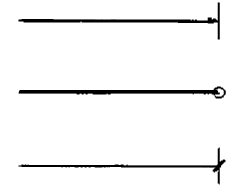
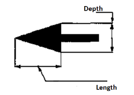
Dimension lines should show distinct termination in the form of arrow heads or oblique strokes orwhere applicable an origin indication (Fig.15). The arrow head included angle is 15°. The originindication is drawn as a small open circle of approximately 3 mm in diameter. The proportion length to depth 3: 1 of arrow head is shown in Fig.16.
|
Figure 15 Termination of dimension lines
|
Figure 16 Proportions of an arrow head
Methods of Indicating Dimensions
The dimensions are indicated on the drawings according to one of the following two methods.
Method I (Aligned method)
Dimensions should be placed parallel to and above their dimension lines and preferably at themiddle, and clear of the line. (Fig. 17).
|
Figure 17
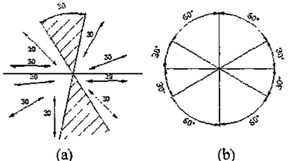
Dimensions may be written so that they can be read from the bottom or from the right side ofthe drawing. Dimensions on oblique dimension lines should be oriented as shown in Fig.18a andexcept where unavoidable, they shall not be placed in the 30° zone. Angular dimensions are oriented as shown in Fig.18b.
|
Figure 18 Angular dimensioning
Method 2(Uni-directional method)
Dimensions should be indicated so that they can be read from the bottom of the drawing only.Non-horizontal dimension lines are interrupted, preferably in the middle for insertion of thedimension (Fig.19a).
Angular dimensions may be oriented as in Fig.19b
|
Figure 19 Uni-directional method
Simple Geometrical constructions
Engineering drawing consists of many geometrical constructions. A few methods areillustrated here without mathematical proofs.
1. To divide a straight line into a given number of equal parts say 5.
construction (Fig. 20)
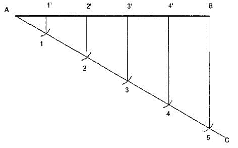
Figure 20 Dividing a line
i. Draw AC at any angle θ to AB.
ii. Construct the required number of equal parts of convenient length on AC like 1,2,3.
iii. Join the last point 5 to B
iv. Through 4, 3, 2, 1 draw lines parallel to 5B to intersect AB at 4',3',2' and 1'.
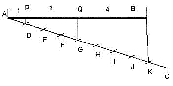
2. To divide a line in the ratio 1: 3: 4.
Construction (Fig. 21)
As the line is to be divided in the ratio 1:3:4 it must be divided into 8 equal divisions.By following the previous example divide AC into 8 equal parts and obtain P and Q to dividethe lineAB in the ratio 1:3:4.
|
Figure 21
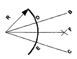
3. To bisect a given angle.
Construction (Fig. 22)
|
Figure 22
1. Draw a line AB and AC making the given angle.
2. With center A and any convenient radius R draw an arc intersecting the sides atD and E.
3. With centers D and E and radius larger than half the chord length DE, draw arcsintersecting at F.
4. JoinAF, <BAF = <PA
Reference Books
1. Madsen, D. P. and Madsen, D. A., (2016), “Engineering Drawing and design”, Delmar Publishers Inc., USA
2. Bhatt, N. D., (2018), “Machine Drawing”, Chartor Publishing house, Anand, India
3. Dhawan, R. K., (2000), “A Textbook Of Engineering Drawing”, S. Chand, New Delhi
4. Luzadder, W. J. and Duff, J. M., (1992), “The Fundamentals of Engineering Drawing: With an Introduction to Interactive Computer Graphics for Design and Production”, Peachpit Press, USA
5. Giesecke, F. E., Mitchell, A., Spencer, H. C., Hill, I. L., Loving, R. O., Dygon, J. T.,
(1990), “Principles of engineering graphics”, McMillan Publishing, USA
6. Jensen, C., Helsel, J. D., Short, D. R., (2008), “Engineering Drawing and Design”,
McGraw-Hill International, SingaporeGuidelines for Laboratory Conduction
