EG
UNIT 3ENGINEERING CURVES
3.1 Introduction to Conics section:The profile of number of objects consists of various types of curves. This chapter deals with various types of curves which are commonly used in engineering practiceas shown below:1. Conic sections 4. Evolutes2. Cycloidal curves 5. Spirals3. Involute 6. Helix.3.1.1
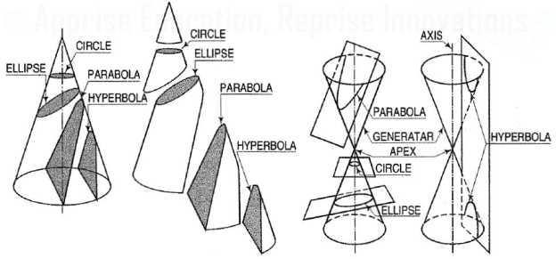
Conic sections:The profile of number of objects consists of various types of curves.1. Conic sections:The section obtained by intersection of a right circular cone by a plane in different positions relative to the axis of the cone are called conics.
Figure 1(i) When the section plane is inclined to the axis and cuts all the generators onone side of the apex, the section is an ellipse [fig. 1].(ii) When the section plane is inclined to the axis and is parallel to one of the generators, the section is a parabola [fig. 1].(iii) A hyperbola is a plane curve having two separate parts or branches, formedwhen two cones that point towards one another are intersected by a planethat is parallel to the axes of the cones.Conic sections are always "smooth". More precisely, they never contain any inflection points. This is important for many applications, such as aerodynamics, civil engineering, mechanical engineering, etc.The conic may be defined as the locus of a point in a plane, wherein the ratio of its distance from a fixed point and a fixed straight line is always constant. The fixed point is called the focus and the fixed line, the directrix.The ratio  is called eccentricity and is denoted by ‘e’. It is always less the 1 for ellipse, equal to 1 for parabola and greater than 1 for hyperbola i.e.(i) ellipse: e < 1(ii) parabola: e = 1(iii) hyperbola: e > 13.1.2
|
 is called eccentricity and is denoted by ‘e’. It is always less the 1 for ellipse, equal to 1 for parabola and greater than 1 for hyperbola i.e.(i) ellipse: e < 1(ii) parabola: e = 1(iii) hyperbola: e > 13.1.2
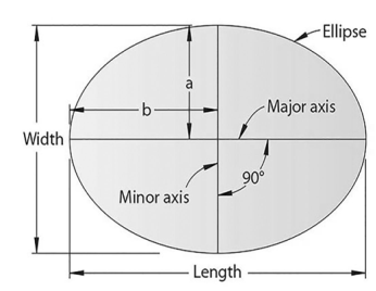
 Ellipse:Use of elliptical curves is made in arches, bridges, dams, monuments, man holes, etc. Mathematically an ellipse can be described by equation  .Here ‘a’ and ‘b’ are half the length of major and minor axes of ellipse and x and y are co-ordinates.
Figure 23.1.3
 .Here ‘a’ and ‘b’ are half the length of major and minor axes of ellipse and x and y are co-ordinates.
|
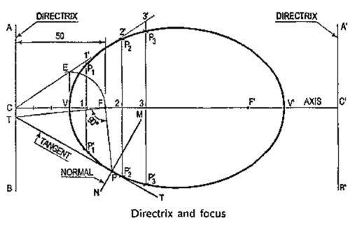
1. General methods of constructing ellipse:Problem 6-1. (fig. 6-2): To construct an ellipse when the distance of the focus from the directrix is equal to 50 mm and eccentricity is 2/3.(i) Draw any vertical line AB as directrix.(ii) At any point C on it, draw the axis perpendicular to the AB (directrix).(iii) Mark a focus F on the axis such that CF = 50 mm.(iv) Divide CF into 5 equal divisions (sum of numerator and denominator of the eccentricity.).(v) Mark the vertex V on the third division-point from C.Thus, eccentricity, e = VF/VC = 2/3.(vi) A scale may now be constructed on the axis, which will directly give the distances in the required ratio.(vii) At V, draw a perpendicular VE equal to VF. Draw a line joining C and E.(viii) Mark any point 1 on the axis and through it, draw a perpendicularto meet CE-produced at 1 '.(ix) With centre F and radius equal to 1-1 ', draw arcs to intersect the perpendicularthrough 1 at points P1 and P' 1.These are the points on the ellipse, because the distance of P1 from ABis equal to C1,P1F = 1-1’and  .Similarly, mark points 2, 3 etc. on the axis and obtain points P2 and P'2 ,P3 and P'3 etc.(x) Draw the ellipse through these points. It is a closed curve having two fociand two directrices.
Figure 33.1.4
 .Similarly, mark points 2, 3 etc. on the axis and obtain points P2 and P'2 ,P3 and P'3 etc.(x) Draw the ellipse through these points. It is a closed curve having two fociand two directrices.
|
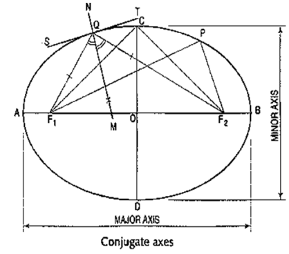
2. Construction of ellipse by other methods:Ellipse is also defined as a curve traced out by a point, moving in the sameplane as and in such a way that the sum of its distances from two fixed pointsis always the same.(i) Each of the two fixed points is called the focus.(ii) The line passing through the two foci and terminated by the curve, is calledthe major axis.(iii) The line bisecting the major axis at right angles and terminated by the curve,is called the minor axis.Conjugate axes: Those axes are called conjugate axes when they are parallel to thetangents drawn at their extremities.In fig. 4, AB is the major axis, CD the minor axis and F1 and F2 are the foci. Thefoci are equidistant from the centreO.
The points A, P, C etc. are on the curve and hence, according to the definition,(AF1 + AF2) = (PF1 + PF2) = (CF1 + CF2) etc.But (AF1 + AF2) = AB. Therefore, (PF1 + PF2) = AB, the major axis.Therefore, the sum of the distances of any point on the curve from the two foci isequal to the major axis.Again, (CF1 + CF2) = ABBut CF1 = CF2, Therefore, CF1 = CF2 = 1/2 AB.Hence, the distance of the ends of the minor axis from the foci is equal to half the equal to the major axis.
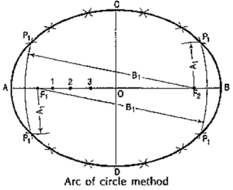
Figure 42. To construct an ellipse, given the major and minor axes. The ellipse is drawn by, first determining many points through which it is known to pass and then, drawing a smooth curve through them, either freehand or with a french curve. Larger the number of points, more accurate the curve will be.3.1.5
|
Method 1: Arcs of circles method,(i) Draw a line AB equal to themajor axis and a line CO equalto the minor axis, bisecting eachother at right angles at O.(ii) With centre C and radius equal to half AB (i.e. AO) draw arcscutting AB at F1 and F2, thefoci of the ellipse.(iii) Mark many points 1, 2,3 etc. on AB.(iv) With centres F1 and F2 andradius equal to A1, draw arcson both sides of AB.(v) With same centres and radius equal to 81, draw arcs intersecting theprevious arcs at four points marked P1.(vi) Similarly, with radii A2 and B2, A3 and B3 etc. obtain more points.(vii) Draw a smooth curve through these points. This curve is the required ellipse.
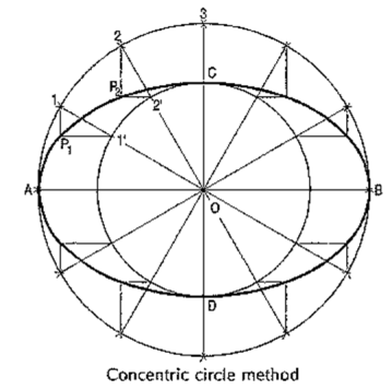
Figure 53.1.6
|
Method 2: Concentric circles method,(i) Draw the major axis AB and the minor axis CD intersecting each other at O.(ii) With centre O and diameters AB and CD respectively, draw two circles.(iii) Divide the major-axis-circle into many equal divisions, say 12 andmark points 1, 2 etc. as shown.(iv) Draw lines joining these points with the centre O and cutting the minor-axis-circleat points 1', 2' etc.(v) Through point 1 on the major-axis-circle, draw a line parallel to CD, the minor axis.(vi) Through point 1' on the minor-axis-circle, draw a line parallel to AB, the majoraxis. The point P1, where these two lines intersect is on the required ellipse.(vii) Repeat the construction through all the points. Draw the ellipse through A,P1, P2 .•• etc.
Figure 63.1.7
|
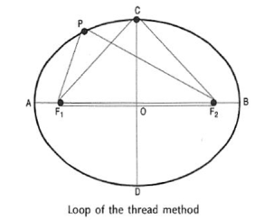
Method 3: Loop of thread method(i) Draw the two axes AB and CD intersecting at O. Locate the foci F1 and F2.(ii) Insert a pin at each focus-point and tie a piece of thread in the form of a loop around the pins, in such a way that the pencil point when placed in the loop (keeping the thread tight), is just on the end C of the minor axis.(iii) Move the pencil around the foci, maintaining an even tension in the thread throughout and obtain the ellipse.It is evident that PF1 + PF2 = CF1 + CF2 etc.
Figure 73.1.8
|
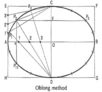
Method 4: Oblong method
Figure 8(i) Draw the two axes AB and CD intersecting each other at O.(ii) Construct the oblong EFGH having its sides equal to the two axes. (iii) Divide the semi-major-axis AO into many equal parts, say 4, and AE into the same number of equal parts, numbering them from A as shown.(iv) Draw lines joining 1 ', 2' and 3' with C.(v) From D, draw lines through 1, 2 and 3 intersecting C'1, C'2 and C'3 at points P1, P2 and P3 respectively.(vi) Draw the curve through A, P1..... C. It will be one quarter of the ellipse.(vii) Complete the curve by the same construction in each of the three remaining quadrants.As the curve is symmetrical about the two axes, points in the remaining quadrantsmay be located by drawing perpendiculars and horizontals from P1, P2 etc. andmaking each of them of equal length on both the sides of the two axes. 3.1.9
|
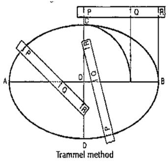
Method 5: Trammel method
Figure 9(i) Draw the two axes AB and CD intersecting each other at O. Along the edge of a strip of paper which may be used as a trammel, mark PQ equal to half the minor axis and PR equal to half the major axis.(ii) Place the trammel so that R ison the minor axis CD and Qon the major axis AB. Then Pwill be on the required ellipse.By moving the trammel to newpositions, always keeping R onCD and Q on AB, obtain otherpoints. Draw the ellipse throughthese points.
|
3.2 Parabola:Use of parabolic curves is made in arches, bridges, sound reflectors, light reflectors, etc. Mathematically it can be described by an equation  or
or  .Methods of constructing Parabola:To draw a parabola with 70 mm as base and 30 mm as the length of the axis.3.2.1
 or
or  .Methods of constructing Parabola:To draw a parabola with 70 mm as base and 30 mm as the length of the axis.3.2.1
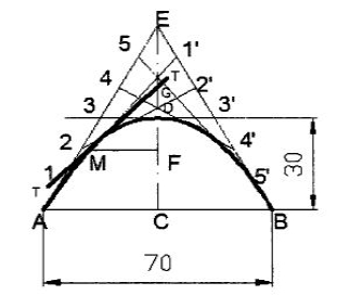
 I. Tangent method:
Figure 101. Draw the base AB and locate its mid-point C.2. Through C, draw CD perpendicular to AB forming the axis3. Produce CD to E such that DE = CD4. Join E-A and E-B. These are the tangents to the parabola at A and B.5. Divide AE and BE into the same number of equal parts and number the points as shown.6. Join 1-1' ,2- 2' ,3- 3' , etc., forming the tangents to the required parabola.7. A smooth curve passing through A, D and B and tangential to the above lines is the required parabola.3.2.2
|
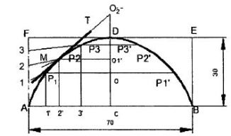
II. Rectangle method:
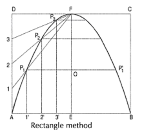
Figure 111. Draw the base AB and axis CD such that CD is perpendicular bisector to AB.2. Construct a rectangle ABEF, passing through C.3. Divide AC and AF into the same number of equal parts and number the points 'as shown.4. Join 1,2 and 3 to D.5. Through 1',2' and 3', draw lines parallel to the axis, intersecting the lines 1D, 2D and 3Dat P1 P2 and P3 respectively.6. Obtain the points P1’, P2’ and P3’, which are symmetrically placed to P1, P2 and P3 withrespect to the axis CD.7. Join the points by a smooth curve forming the required parabola.General method of construction of a parabola:To construct a parabola, when the distance of the Focus from the directrix is 50 mm.
(i) Draw the directrix AB and the axis CD.(ii) Mark focus Fon CD, 50 mm from C.(iii) Bisect CF in V the vertex (because eccentricity = 1).(iv) Mark many points 1, 2, 3 etc. on the axisand through them, draw perpendiculars to it.(v) With centre F and radius equal to C1, draw arcs cutting the perpendicular through 1 at P1 and P’1.(vi) Similarly, locate points P2 and P’2, P3 and P’3 etc. on both the sides of the axes.(vii) Draw a smooth curve through these points. This curve is the required parabola. It is an open curve.1. Rectangle method:Problem: To construct a parabola given the base and the axis.(i) Draw the base AB.(ii) At its mid-point E, draw the axis ff at right angles to AB.(iii) Construct a rectangle ABCD, making side BC equal to EF.(iv) Divide AE and AD into the same number of equal parts and name them as shown (starting from A).(v) Draw lines joining F with points 1, 2 and 3. Through 1 ', 2' and 3', draw perpendiculars to AB intersecting F1, F2 and F3 at points P1, P2 and P3 respectively.(vi) Draw a curve through A, P1, P2 etc. It will be a half parabola.Repeat the same construction in the other half of the rectangle to complete the parabola. Or, locate the points by drawing lines through the points P1, P2 etc. Parallel to the base and making each of them of equal length con both the sides of ff, e.g. P10 = OP'1. AB and EF are called the base and the axis respectively of the parabola.
Figure 12
|
|
|
Rectangular hyperbolaIt is a curve traced out by a point moving in such away that the product of its distances from two fixed lines at right angles to each other is a constant. The fixed lines are called asymptotes.This curve graphically represents the Boyle's Law, viz. P x V = a, P = pressure = volume and a is constant. It is also useful in design of water channels.General method of construction of a hyperbola:Mathematically, we can describe a hyperbola by 1. Construct a hyperbola, from the directrix is 65 mm and eccentricity is3/2.
Figure 13 (i) Draw the directrix AB and the axis CD. When the distance of the focus(ii) Mark the focus F on CD and 65 mm from C.(iii) Divide CF into 5 equal divisions and mark V the vertex, on the second division from C.Thus, eccentricity = VF/VC = 3/2.To construct the scale for the ratio 3/2, draw aline VE perpendicular to CD such that VE =VF. Join C with E.Thus, in triangle CVE, VE/VC = VF/VC = 3/2(iv) Mark any point 1 on the axis and through it, drawn perpendicular to meet CE-produced at 1'.(v) With centre F and radius equal to 1-1 ', draw arcs intersecting the perpendicular through 1at P1 and P'1·(vi) Similarly, mark a number of points 2, 3 etc. And obtain points P2 and P'2, P3 and P'3 etc.(vii) Draw the hyperbola through these points.3.3.2
 1. Construct a hyperbola, from the directrix is 65 mm and eccentricity is3/2.
|
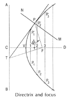
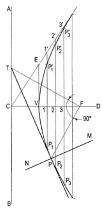
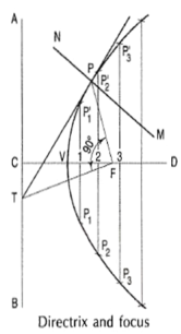
Tangents and Normal to Conic:The common rule for drawing tangents and normal:When a tangent at any point on the curve is produced to meet the directrix, the line joining the focus with this meeting point will be at right angles to the line joining the focus with the point of contact.The normal to the curve at any point is perpendicular to the tangent at that point.
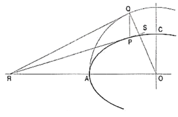
1. To draw a tangent at any point Pon the conics(i) Join P with F.(ii) From F, draw a line perpendicular to PF to meet AB at T.(iii) Draw a line through T and P. This line is the tangent to the curve.(iv) Through P, draw a line NM perpendicular to TP. NM is the normal to the curve.2. Other methods of drawing tangents to conicsMethod I: 1. To draw a tangent to an ellipse at any point P on it.(i) With O, the centre of the ellipse as centre, and one half the major axis as radius, draw a circle.(ii) From P, draw a line parallel to the minor axis, cutting the circle at a point Q.
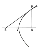
Figure 15(iii) Draw a tangent to the circle at the point Q cutting the extended major axis at a point R.From R, draw a line RS passing through P. RS is the required tangent to the ellipse. Method II: When an axis of parabola is given,To draw a tangent to a parabola at any point P on it.(i) From P, draw a perpendicular PA to the axis, intersecting it at a point A.Mark a point B on the axis such that BV = VA. Draw a line from B passing through P.Then this line is the required tangent.
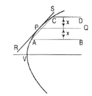
Figure 16(ii) Through P, draw a line PQ parallel to the axis (fig. 17).Draw two lines AB and CD parallel to, equidistant from and on opposite sides of PQ, and cutting the parabola at points A and C. Draw a line joining A with C.Through P, draw a line RS parallel to AC. RS is the required tangent.
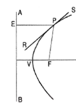
Figure 17Method 3: When the focus and the directrix are given.(i) From P draw a line PE perpendicular to the directrix AB, meeting it at a point f.(ii) Draw a line joining P with the focus F.(iii) Draw the bisector RS of angle EPF.Then RS is the required tangent.
Figure 18
|
 1. To draw a tangent to an ellipse at any point P on it.(i) With O, the centre of the ellipse as centre, and one half the major axis as radius, draw a circle.(ii) From P, draw a line parallel to the minor axis, cutting the circle at a point Q.
|
|
|
|
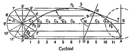
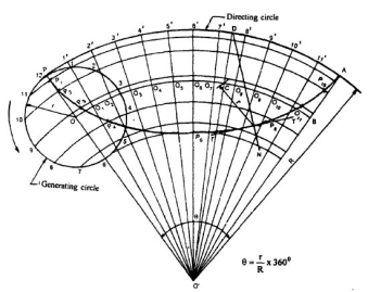
3.4 Cycloidal Curves:Cycloid is a curve generated by a point on the circumference of a circle which rolls along a straight line. It can be described by an equation,y = a (1 - cosθ) or x = a (θ - sinθ)To construct a cycloid, given the diameter of the generating circle.(i) With centre C and given radius R, draw a circle. Let P be the generating point.(ii) Draw a line PA tangential to and equal to the circumference of the circle.(iii) Divide the circle and the line PA into the same number of equal parts, say 12,and mark the division-points as shown.(iv) Through C, draw a line CB parallel and equal to PA.(v) Draw perpendiculars at points 1, 2 etc. cutting CB at points C1, C2 etc.
Figure 19Assume that the circle starts rolling to the right. When point 1' coincides with 1, centre C will move to C1. In this position of the circle, the generating point P will have moved to position P1 on the circle, at a distance equal to P'1 from point 1. It is evident that P1 lies on the horizontal line through 1' and at a distance R from C1. Similarly, P2 will lie on the horizontal line through 2' and at the distance R from C2.Construction:(vi) Through the points 1 ', 2' etc. draw lines parallel to PA.(vii) With centres C1, C2 etc. and radius equal to R, radius of generating circle, draw arcs cutting the lines through 1 ', 2' etc. at points P1, P2 etc. respectively. Draw a smooth curve through points P, P1, P2 …. A. This curve is the required cycloid.Normal and tangent to a cycloid curve: The rule for drawing a normal to all cycloidal curves:The normal at any point on a cycloidal curve will pass through the corresponding point of contact between the generating circle and the directing line or circle. The tangent at any point is perpendicular to the normal at that point.
|
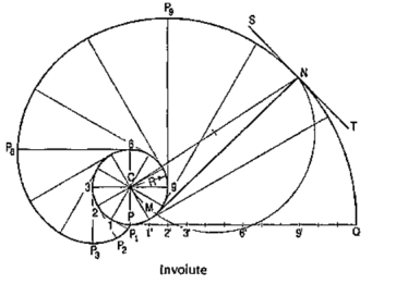
3.5 Involute:The involute is a curve traced out by an end of a piece of thread unwound from a circle or a polygon, the thread being kept tight. It may also be defined as a curve traced out by a point in a straight line which rolls without slipping along a circle or a polygon. Involute of a circle is used as teeth profile of gear wheel.Mathematically it can be described by x = rcosθ + rθsinθ, y = rsinθ - rθcosθ,where "r" is the radius of a circle.Problem: To draw an involute of a given circle.With centre C, draw the given circle. Let P be the starting point, i.e. the end of the thread.Suppose the thread to be partly unwound, say upto a point 1. P will move to aposition P1 such that 1P1 is tangent to the circle and is equal to the arc 1 P. P1 will bea point on the involute.Construction:(i) Draw a line PQ, tangent to the circle and equal to the circumference of the circle.(ii) Divide PQ and the circle into 12 equal parts.(iii) Draw tangents at points 1, 2, 3 etc. and mark on them points P1, P2, P3 etc.such that 1P1 = P1', 2P2 = P2', 3P3 = P3' etc.Draw the involute through the points P, P1, P2 .... etc.Normal and tangent to an involute:The normal to an involute of a circle is tangent to that circle.Problem:To draw a normal and a tangent to the involute of a circleat a point N on it.
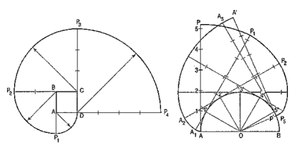
Figure 20(i) Draw a line joining C with N.(ii) With CN as diameter describe a semi-circle cutting the circle at M.(iii) Draw a line through N and M. This line is the normal. Draw a line ST, perpendicular to NM and passing through N. ST is the tangent to the involute. Problem: Trace the paths of the ends of a straight-line AP, 100 mm long, when it rolls, without slipping, on a semi-circle having its diameter AB, 75 mm long. (Assume the line AP to be tangent to the semi-circle in the starting position.)
Figure 21
|
|
(i) Draw the semi-circle and divide it into six equal parts.(ii) Draw the line AP and mark points 1, 2 etc. such that A1 = arc A1 ', A2 = arc A2' etc. The last division SP will be of a shorter length. On the semi-circle, mark a point P' such that S'P' = SP.(iii) At points 1 ', 2' etc. draw tangents and on them,mark points P1, P2 etc. suchthat 1' P1 = 1P, 2' P2 =2P .... and 5' P5 = 5' P6 =SP. Similarly, mark pointsA1, A2 etc. such that A11'= A1, A22' = A2 .... and A'p'= AP. Draw the requiredcurves through points P,P1 .... and P', and throughpoints A, A1 .... and A'.If AP is an inelastic string with the end A attached to the semicircle, the end P will trace out the same curve PP' when the string is wound round the semi-circle.
Figure 22
|
3.6 Involute:The involute is a curve traced out by an end of a piece of thread unwound from a circle or a polygon, the thread being kept tight. It may also be defined as a curve traced out by a point in a straight line which rolls without slipping along a circle or a polygon.It is used as teeth profile of gear wheel.Mathematically it can be described as by  ,
,  , where “r” is the radius of the circle.An involute is a curve traced by a point on a perfectly flexible string, while unwinding from around a circle or polygon the string being kept taut (tight). It is also a curve traced by a point on a straight-line while the line is rolling around a circle or polygon without slipping.To draw an involute of a given square.1. Draw the given square ABCD of side a.2. Taking A as the starting point, with centre B and radius BA=a, draw an arc to intersect theline CB produced at Pl.3. With Centre C and radius CP1 =2 a, draw on arc to intersect the line DC produced at P 2.4. Similarly, locate the points P3 and P4.
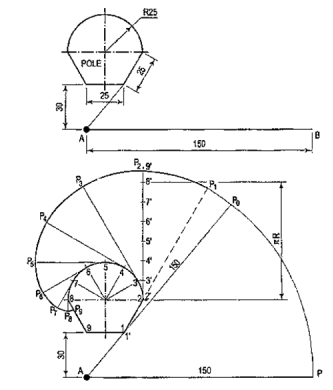
Figure 23The curve through A, P1, P2, P3 and P4 is the required involute.A P4 is equal to the perimeter of the square.AP is a rope 1.50-metre-long, tied to peg at A as shown in fig. 24. Keeping it always tight, the rope is wound round the pole. Draw the curve traced out by the end P. Use scale 1 :20.Draw given figure to the scale.(ii) From A, draw a line passing through 1. A as centre and AP as radius, draw the arc intersecting extended line A1' at P0. Extend the side 1-2, 1 as centre and 1 'Po as radius, draw the arc to intersect extended line 1-2 at P1.(iii) Divide the circumference of the semicircle into six equal parts and label it as 2, 3, 4, 5, 6, 7 and 8.(iv) Draw a tangent to semicircle from 2 such that 2'-P1 = 2'-P2 . Mark 8' on this tangent such that 2'-8' = nR. Divide 2'-8' into six equal parts.(v) Similarly draw tangents at 3, 4, 5, 6, 7 and 8 in anti-clockwise direction such that 3-P3 = 3'-9', 4-P4 = 4'-9', 5-P5 = 5'-9', 6-P6 = 6'-9', 7-P7 = 7'-9', 8-P8 = 8'-9' and 8-P9 = 8'-9' respectively.(vi) Join P1, P2, ....• , P9 with smooth curve.
Figure 24
 ,
,  , where “r” is the radius of the circle.An involute is a curve traced by a point on a perfectly flexible string, while unwinding from around a circle or polygon the string being kept taut (tight). It is also a curve traced by a point on a straight-line while the line is rolling around a circle or polygon without slipping.To draw an involute of a given square.1. Draw the given square ABCD of side a.2. Taking A as the starting point, with centre B and radius BA=a, draw an arc to intersect theline CB produced at Pl.3. With Centre C and radius CP1 =2 a, draw on arc to intersect the line DC produced at P 2.4. Similarly, locate the points P3 and P4.
|
|
3.7 Spiral:If a line rotates in a plane about one of its ends and if at the same time, a point moves along the line continuously in one direction, the curve traced out by the moving point is called a spiral. The point about which the line rotates is called a pole.The line joining any point on the curve with the pole is called the radius vector and the angle between this line and the line in its initial position is called the vectorial angle.
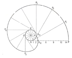
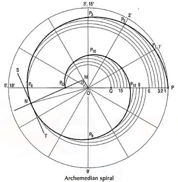
Archemedian spiral:It is a curve traced out by a point moving in such a way that its movement towards and away from the pole is uniform with the increase of the vectorial angle from the starting line.The use of this curve is made in teeth profiles of helical gears, profile of cams, etc.To construct an Archemedian spiral of  convolutions given the greatest and the shortest radii.Let O be the pole, OP the greatest radius and OQ the shortest radius.(i) With centre O and radius equal to OP, draw a circle. OP revolves around0 for
  revolutions.During this period, P moves towards 0, the distance equal to (OP - OQ) i.e. QP.(ii) Divide the angular movements of OP, viz
  revolutions i.e. 540°and theline QP into the same number of equal parts, say 18 (one revolutiondivided into 12 equal parts).When the line OP moves through one division, i.e. 30°, the point P willmove towards O by adistance equal to one division of QP to a point P1.(iii) To obtain points systematically draw arcs with centre O and radii O1’, O2’, O3’ etc. intersecting lines O1’, O2’, O3’ etc. at points P1, P2, P3 etc.respectively.In one revolution, P will reach the 12th division along QP and in the nexthalf revolution it will be at the point PQ on the line 18'-0.(iv) Draw a curve through points P, P1, P2, PQ. This curve is the requiredArchemedian spiral.The constant of the curve is equal to the difference between the lengths of anytwo radii divided by the circular measure of the angle between them.OP and OP3 (fig. 6-63) are two radii making go0 angle between them. Incircular measure in radian,
 . Therefore, the constant of the curve
Figure 25Reference Books1. Madsen, D. P. and Madsen, D. A., (2016), “Engineering Drawing and design”, Delmar Publishers Inc., USA2. Bhatt, N. D., (2018), “Machine Drawing”, Chartor Publishing house, Anand, India3. Dhawan, R. K., (2000), “A Textbook Of Engineering Drawing”, S. Chand, New Delhi4. Luzadder, W. J. and Duff, J. M., (1992), “The Fundamentals of Engineering Drawing: With an Introduction to Interactive Computer Graphics for Design and Production”, Peachpit Press, USA5. Giesecke, F. E., Mitchell, A., Spencer, H. C., Hill, I. L., Loving, R. O., Dygon, J. T.,(1990), “Principles of engineering graphics”, McMillan Publishing, USA6. Jensen, C., Helsel, J. D., Short, D. R., (2008), “Engineering Drawing and Design”,McGraw-Hill International, SingaporeGuidelines for Laboratory Conduction
 convolutions given the greatest and the shortest radii.Let O be the pole, OP the greatest radius and OQ the shortest radius.(i) With centre O and radius equal to OP, draw a circle. OP revolves around0 for
  revolutions.During this period, P moves towards 0, the distance equal to (OP - OQ) i.e. QP.(ii) Divide the angular movements of OP, viz
  revolutions i.e. 540°and theline QP into the same number of equal parts, say 18 (one revolutiondivided into 12 equal parts).When the line OP moves through one division, i.e. 30°, the point P willmove towards O by adistance equal to one division of QP to a point P1.(iii) To obtain points systematically draw arcs with centre O and radii O1’, O2’, O3’ etc. intersecting lines O1’, O2’, O3’ etc. at points P1, P2, P3 etc.respectively.In one revolution, P will reach the 12th division along QP and in the nexthalf revolution it will be at the point PQ on the line 18'-0.(iv) Draw a curve through points P, P1, P2, PQ. This curve is the requiredArchemedian spiral.The constant of the curve is equal to the difference between the lengths of anytwo radii divided by the circular measure of the angle between them.OP and OP3 (fig. 6-63) are two radii making go0 angle between them. Incircular measure in radian,
 . Therefore, the constant of the curve
|
0 matching results found
Browse by Topics
