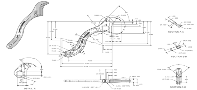
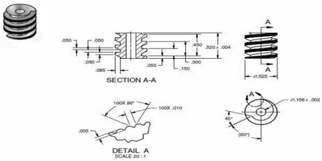
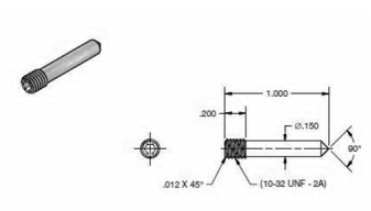
Orthographic Projections:
If straight lines are drawn from various points on the contour of an object to meet a plane, the object is said to be projected on that plane. The figure formed by joining, in correct sequence, the points at which these lines meet the plane, is called the projection of the object. The lines from the object to the plane are called projectors.
Methods of Projection:
Following four methods of projection are commonly used,
1) Orthographic projection.
2) Isometric projection.
3) Oblique projection.
4) Perspective projection.
In the above methods 2, 3 and 4 represent the object by a pictorial view as eyes see it. In these methods of projection, a three-dimensional object is represented on a projection plane by one view only, while in the orthographic projection an object is represented by two or three views on the mutual perpendicular projection planes. Each projection view represents two dimensions of an object. For the complete description of the three-dimensional object at least two or three views are required.
4.1.1 Orthographic Projection:
Theory of orthographic projection:
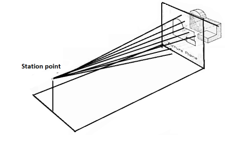
Let us suppose that a transparent plane has been set up between an object and the station point of an observer's eye (Fig. 1). The intersection of this plane with the rays formed by lines of sight from the eye to all points of the object would give a picture that is practically the same as the image formed in the eye of the observer. This is perspective projection.
|
Figure 1 Perspective projection. The rays of the projection converge at the station point from which the object is observed.
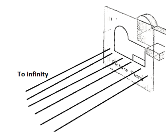
If the observer would then walk backward from the station point until he reached a theoretically infinite distance, the rays formed by lines of sight from his eye to the object would grow longer and finally become infinite in length, parallel to each other, and perpendicular to the picture plane. The image so formed on the picture plane is what is known as "orthographic projection." See Fig.
|
Figure 2 Orthographic projection.
Basically, orthographic projections could be defined as any single projection made by dropping perpendiculars to a plane. However, it has been accepted through long usage to mean the combination of two or more such views, hence the following definition has been put forward: Orthographic projection is the method of representing the exact shape of an object by dropping perpendiculars from two or more sides of the object to planes, generally at right angles to each other; collectively, the views on these planes describe the object completely. (The term "orthogonal" is sometimes used for this system of drawing.)
4.1.2 Orthographic views:
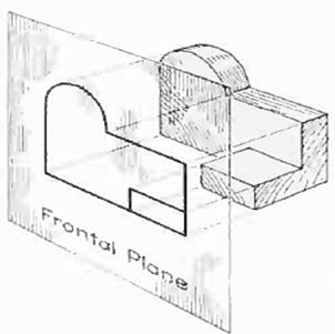
The rays from the picture plane to infinity may be discarded and the picture, or "view," thought of as being found by extending perpendiculars to the plane from all points of the object, as in Fig. 3. This picture, or projection on a frontal plane, shows the shape of the object when viewed from the front, but it does not tell the shape or distance from front to rear. Accordingly, more than one projection are required to describe the object.
|
Figure 3 The frontal plane of projection. This produces the front view of the object.
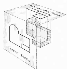
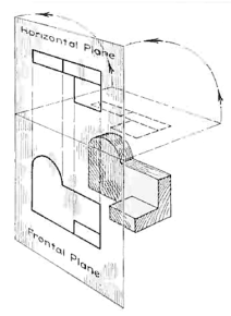
In addition to the frontal plane, imagine another transparent plane placed horizontally above the object, as in Fig. 4. The projection on this plane, found by extending perpendiculars to it from the object, will give the appearance of the object as if viewed from directly above and will show the distance from front to rear.
|
Figure 4 The frontal and horizontal planes of projections. Projection on the horizontal plane produces the top view of the object.
If this horizontal plane is now rotated into coincidence with the frontal plane, as in Fig. 5, the two views of the object will be in the same plane, as if on a sheet of paper.
|
Figure 5 The horizontal plane rotated into the same plane as the frontal plane.
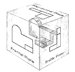
Now imagine a third plane, perpendicular to the first two (Fig. 6). This plane is called a "profile plane," and a third view can be projected on it. This view shows the shape of the object when viewed from the side and the distance from bottom to top and front to rear.
|
Figure 6 The three planes of projection: frontal, horizontal and profile. Each is perpendicular to other two.
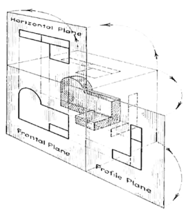
The horizontal and profile planes are shown rotated into the same plane as the frontal plane (again thought of as the plane of the drawing paper) in Fig. 7. Thus, related in the same plane, they give correctly the three-dimensional shape of the object.
|
Figure 7 The horizontal and profile planes rotated into the same plane as the frontal plane. This makes it possible to draw three views of the object.
In orthographic projection the picture planes are called "planes of projection"; and the perpendiculars, "projecting lines" or "projectors."
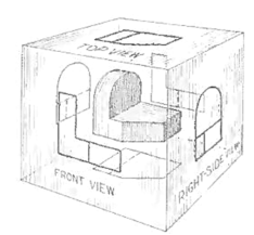
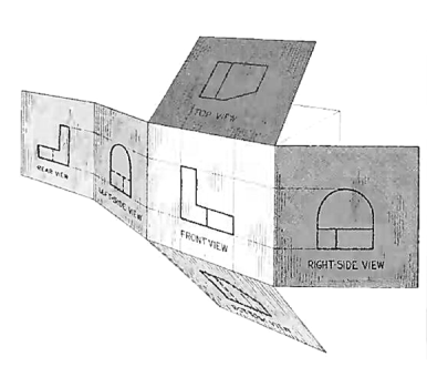
The object can be surrounded by a set of six planes, each at right angles to the four adjacent to it, as in Fig. 8. On these planes, views can be obtained of the object as it is seen from the top, front, right side, left side, bottom, and rear.
|
Figure 8 "The transparent box." This encloses the object with another frontal plane below, and another profile plane to the left of the object.
Think now of the six sides, or planes, of the box as being opened, as in Fig. 9, into one plane, the plane of the paper. The front is already in the plane of the paper, and the other sides are, as it were, hinged and rotated into position as shown.
|
Figure 9
Four quadrants:
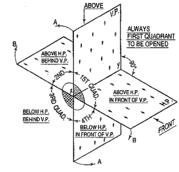
When the planes of projection are extended beyond the line of intersection, they form four quadrants or dihedral angles which may be numbered as in fig. The object may be situated in any one of the quadrants, its position relative to the planes being described as "above or below the H.P." and "in front of or behind the V.P."
|
Figure 10
We have assumed the object to be situated in front of the V.P. and above the H.P. i.e. in the first quadrant and then projected it on these planes. This method of projection is known as first-angle projection method. The object lies between the observer and the plane of projection. In this method, when the views are drawn in their relative positions, the top view comes below the front view. In other words, the view seen from above is placed on the other side of (i.e. below) the front view. Each projection shows the view of that surface (of the object) which is remote from the plane on which it is projected, and which is nearest to the observer.
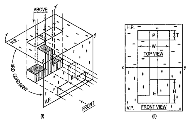
In this method of projection, the object is assumed to be situated in the third quadrant [fig. 11(a)]. The planes of projection are assumed to be transparent. They lie between the object and the observer. When the observer views the object from the front, the rays of sight intersect the V.P. The figure formed by joining the points of intersection in correct sequence is the front view of the object. The top view is obtained in a similar manner by looking from above. When the two planes are brought in line with each other, the views will be shown in fig.11 (b). The top view in this case comes above the front view.
|
Figure 11
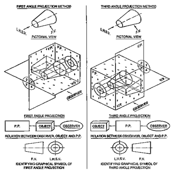
4.3.3 Symbols for methods of projection:
For every drawing it is essential to indicate the method of projection adopted. This is done by means of a symbolic figure drawn within the title block on the drawing sheet. These symbolic figures are the projections of a frustum of cone of convenient dimensions according to the size of drawing and side view.
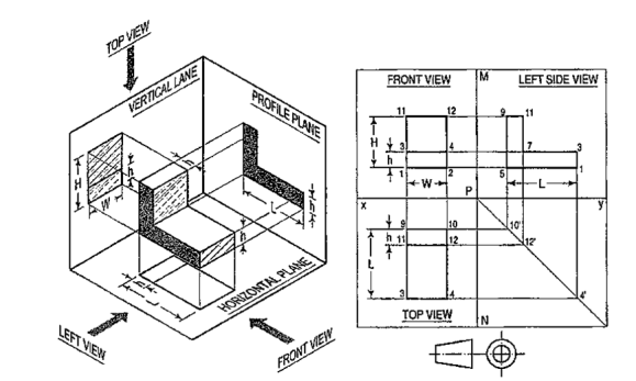
Problems:1) A L-shaped solid object having dimensions of length (L), width (W) and height (H). If this object is lying in the first quadrant. Draw its front view, top view.
|
Steps:
(i) Mark the visible corners of the given block as shown front view: Assume that you are viewing the object in the direction of the arrow towards the imaginary V.P. What you will see is a rectangle of height (H) and width (W) on V.P. This will be the front view. To draw this view:
(ii) Draw a reference line xy, which represents the intersecting line of the planes V.P. and H.P. Draw a rectangle as shown W and H, above xy make sure that the width is parallel to the Iinexy. The rectangle is the front orthogonal view of the object.
(iii) Draw a line parallel to and thickness of h to the line 1-2. The rectangle 1-2-4-3 is the front view of the horizontal L-shaped stem of the object.
|
Figure 13
4.3.4 Drawing top orthogonal view:
(iv) Draw vertical projectors from 1 and 2 and extend them beyond the line xy. Draw a line 9-10 below and parallel to the reference line xy. Draw the lines 9-3 and 10-4 equal to the length L of the object. Join line 3-4. The rectangle 9-10-3-4 is the top view of the object.
(v) Draw a line 11-12 parallel to and below 9-10 of thickness h. The rectangle 9-11-12-10 is the view of the vertical stem of the object.
4.3.5 Drawing the side orthogonal view:
(vi) Draw a reference vertical line MN at right angles to xy cutting it at P. From P draw a construction line at 45° in the fourth quadrant.
(vii) Project lines from the points 10, 12 and 4 of the top view to meet this inclined line at 1 O', 12' and 4'.
(viii) Project lines from points 2, 4 and 12 from the front view parallel to line xy. From points 1 O', 12' and 4' project lines vertically upwards to meet these horizontal projections.
(ix) Join points 5-1-3-7-11-9. This will be the side view of the object.
(x) Finally draw the symbol of first angle projection at the right bottom corner of the drawing.
A point may be situated, in space, in any one of the four quadrants formed by the two principal planes of projection or may lie in any one or both. Its projections are obtained by extending projectors perpendicular to the planes.
One of the planes is then rotated so that the first and third quadrants are opened out. The projections are shown on a flat surface in their respective positions either above or below or in xy.
4.4.1 If a point is situated in the first quadrant,
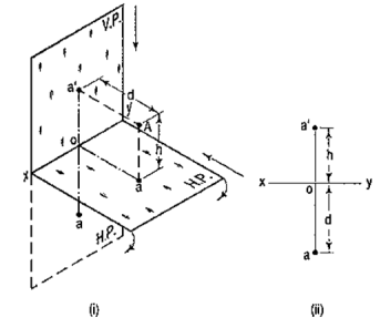
The pictorial view [fig. 14 (i)] shows a point A situated above the H.P. and in front of the V.P., i.e. in the first quadrant. a' is its front view and the top view. After rotation of the plane, these projections will be shown in fig. 14 (ii).
|
Figure 14
The front view a' is above xy and the top view a below it. The line joining a' and a (which also is called a projector), intersects xy at right angles at a point o. It is quite evident from the pictorial view that a'o = Aa, i.e. the distance of the front view from xy = the distance of A from the H.P. viz. h. Similarly, ao = Aa',i.e. the distance of the top view from xy = the distance of A from the V.P. viz. d.
4.4.2 If a point is situated in second quadrant,
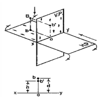
A point B (fig. 15) is above the H.P. and behind the V.P., i.e. in the second quadrant. b' is the front view and b the top view. When the planes are rotated, both the views are seen above xy. Note that b'o = Bb and bo = Bb'.
|
Figure 15
4.4.3 If a point is situated in third quadrant,
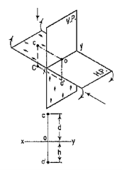
A point C (fig. 16) is below the H.P. and behind the Y.P., i.e. in the third quadrant. Its front view c' is below xy and the top view c above xy. Also, c'o = Cc and co = Cc'.
|
Figure 16
4.4.4 If a point is situated in 4th quadrant,
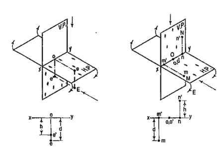
A point f (fig. 17) is below the H.P. and in front of the V.P., i.e. in the fourth quadrant. Both its projections are below xy, and e'o = Ee and eo = Ee'.
|
Figure 17
General conclusions:
1. The fine joining the top view and the front view of a point is always perpendicular to xy. It is called a projector.
2. When a point is above the H.P., its front view is above xy; when it is below the H.P., the front view is below xy. The distance of a point from the H.P. is shown by the length of the projector from its front view to xy.
3. When a point is in front of the V.P., its top view is below xy; when it is behind the V.P., the top view is above xy. The distance of a point from the V.P. is shown by the length of the projector from its top view to xy.
4. When a point is in a reference plane, its projection on the other reference plane is in xy.
Examples:
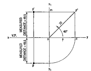
1. A point P is in the first quadrant. Its shortest distance from the intersection point of H.P., V.P. and Auxiliary vertical plane, perpendicular to the H.P. and V.P. is 70 mm and it is equidistant from principal planes (H.P. and V.P.). Draw the projections of the point and determine its distance from the H.P. and V.P.
|
Figure 18
Note: ‘O’ represents intersection of H.P., V.P. and A.V.P.
Drawing steps:
1. Draw xy and x1 y1 perpendicular reference lines.
2. ‘O’ represents intersection of H.P., V.P. and A.V.P.
3. Draw from O a line inclined at 45° of 70 mm length.
4. Project from P" on xy line and x1 y1. The projections are n and m respectively as shown in figure. From O draw arc intersecting x1 y1.
5. Draw a parallel line at convenient distance from x1 y1. Extend P"m to intersect
a parallel line at p' and p as shown.
6. Measure distance from xy line, which is nearly 49.4974 mm say 49.5 mm.
A straight line is the shortest distance between two points. Hence, the projections of a straight line may be drawn by joining the respective projections of its ends which are points.
The position of a straight line may also be described with respect to the two reference planes. It may be:
1. Parallel to one or both the planes.
2. Contained by one or both the planes.
3. Perpendicular to one of the planes.
4. Inclined to one plane and parallel to the other.
5. Inclined to both the planes.
6. Projections of lines inclined to both the planes.
7. Line contained by a plane perpendicular to both the reference planes.
8. True length of a straight line and its inclinations with the reference planes.
9. Traces of a line.
10. Methods of determining traces of a line.
11. Traces of a line, the projections of which are perpendicular to xy.
12. Positions of traces of a line.
Line parallel to one or both the planes:
|
Figure 19
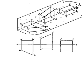
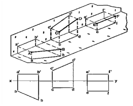
(a) Line AB is parallel to the H.P.
a and b are the top views of the ends A and B respectively. It can be clearly seen that the figure ABba is a rectangle. Hence, the top view ab is equal to AB.
a'b' is the front view of AB and is parallel to xy.
(b) Line CD is parallel to the V.P. The line c'd' is the front view and is equal to CD; the top view cd is parallel to xy.
(c) Line ff is parallel to the H.P. and the V.P. ef is the top view and e'f' is the front view; both are equal to ff and parallel to xy.
Hence, when a line is parallel to a plane, its projection on that plane is equal to its true length; while its projection on the other plane is parallel to the reference line.
Line contained by one or both the planes:
|
Figure 20
Line AB is in the H.P. Its top view ab is equal to AB; its front view a' b' is in xy.
Line CD is in the V.P. Its front view c'd' is equal to CO; its top view cd is in xy.
Line ff is in both the planes. Its front view e' f' and the top view ef coincide with each other in xy.
Hence, when a line is contained by a plane, its projection on that plane is equal to its true length; while its projection on the other plane is in the reference line.
Line perpendicular to one of the planes:
When a line is perpendicular to one reference plane, it will be parallel to the other.
|
Figure 21
(a) Line AB is perpendicular to the H.P. The top views of its ends coincide in the point a. Hence, the top view of the line AB is the point a. Its front view a' b' is equal to AB and perpendicular to xy.
(b) Line CD is perpendicular to the V.P. The point d' is its front view and the line cd is the top view. cd is equal to CD and perpendicular to xy.
Hence, when a line is perpendicular to a plane its projection on that plane is a point; while its projection on the other plane is a line equal to its true length and perpendicular to the reference line.
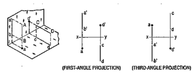
In first-angle projection method, when top views of two or more points coincide, the point which is comparatively farther away from xy in the front view will be visible; and when their front views coincide, that which is farther away from xy in the top view will be visible.
In third-angle projection method, it is just the reverse. When top views of two or more points coincide the point, which is comparatively nearer xy in the front view will be visible; and when their front views coincide, the point which is nearer xy in the top view will be visible.
Line inclined to one plane and parallel to the other:
|
Figure 22
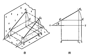
The inclination of a line to a plane is the angle which the line makes with its projection on that plane.
Line PQ1 [fig. 22 (i)] is inclined at an angle 8 to the H.P. and is parallelto the V.P. The inclination is shown by the angle 8 which PQ1 makes withits own projection on the H.P., viz. the top view pq1.
The projections [fig. 22 (ii)] may be drawn by first assuming the line to be parallel to both the H.P. and the V.P. Its front view p'q' and the top view pq will both be parallel to xy and equal to the true length. When the line is turned about the end P to the position PQ1 so that it makes the angle 8 with the H.P. while remaining parallel to the V.P., in the front view the point q' will move along an arc drawn with p' as center and p'q' as radius to a point q'1 so that p'q'1 makes the angle 8 with xy. In the top view, q will move towards p along pq to a point q1 on the projector through q'1. p'q'1 and pq1 are the front view and the top view respectively of the line PQ1.
Line inclined to both the planes:
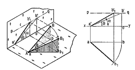
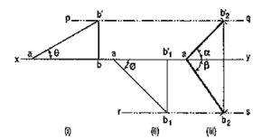
A line AB (fig. 23) is inclined at θto the H.P. and is parallel to the V.P.The end A is in the H.P. AB is shown as the hypotenuse of a right-angledtriangle, making the angle θ with the base.
|
Figure 23
The top view ab is shorter than AB and parallel to xy. The front view a'b' is equal to AB and makes the angle θ with xy.
Keeping the end, A fixed and the angle θ with the H.P. constant, if the end B is moved to any position, say B1, the line becomes inclined to the V.P. also.
In the top view, b will move along an arc, drawn with a as center and ab as radius, to a position b1. The new top view ab1 is equal to ab but shorter than AB.
In the front view, b' will move to a point b'1 keeping its distance from xy constant and equal to b'o; i.e. it will move along the line pq, drawn through b' and parallel to xy. This line pq is the locus or path of the end B in the front view. b'1 will lie on the projector through b1. The new front view a'b'1 is shorter than a'b' (i.e. AB) and makes an angle a with xy. a is greater than θ.
Thus, if the inclination θ of AB with the H.P.is constant, even when it is inclined to the V.P.
(i) its length in the top view, viz. ab remains constant; and
(ii) the distance between the paths of its ends in the front view,viz. b'o remains constant.
|
Figure 24
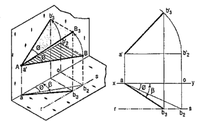
b) The same line AB (fig. 24) is inclined at ϕ to the V.P. and is parallel to the H.P. Its end A is in the V.P. AB is shown as the hypotenuse of a right-angled triangle making the angle ϕ with the base.
The front view a'b'2 is shorter than AB and parallel to xy. The top view ab2 is equal to AB and makes an angle ϕ with xy.
Keeping the end, A fixed and the angle ϕ with the V.P. constant, if B is moved to any position, say B3, the line will become inclined to the H.P. also.
In the front view, b'2, will move along the arc, drawn with a' as center and a'b'2 as radius, to a position b'3. The new front view a'b'3 is equal to a'b'2 but is shorter than AB.
In the top view, b2 will move to a point b3 along the line rs, drawn through b2 and parallel to xy, thus keeping its distance from the path of a, viz. b2o constant. rs is the locus or path of the end B in the top view. The point b3 lies on the projector through b'3. The new top view ab3 is shorter than ab2 (i.e. AB) and makes an angle β with xy. β is greater than ϕ.
Here also we find that, if the inclination of AB with the V.P. does not change, even when it becomes inclined to the H.P.
(i) its length in the front view, viz. a'b'2 remains constant; and
(ii) the distance between the paths of its ends in the top view, viz. b2o remains constant.
Hence, when a line is inclined to both the planes, its projections are shorter than the twe length and inclined to xy at angles greater than the true inclinations. These angles viz. α and β are called apparent angles of inclination.
Traces of a line:
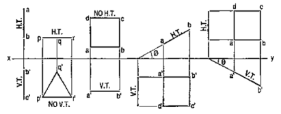
When a line is inclined to a plane, it will meet that plane, produced if necessary. The point in which the line or line-produced meets the plane is called its trace.
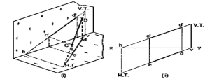
The point of intersection of the line with the H.P. is called the horizontal trace, usually denoted as H.T. and that with the V.P. is called the vertical trace or V.T.
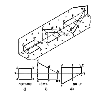
Refer to fig. 25.
(i) A line AB is parallel to the H.P. and the V.P. It has no trace.
(ii) A line CD is inclined to the H.P. and parallel to the V.P. It has only the H.T. but no V.T.
(iii) A line ff is inclined to the V.P. and parallel to the H.P. It has only the V.T. but no H.T.
|
Figure 25
Thus, when a line is parallel to a plane it has no trace upon that plane.
|
Figure 26
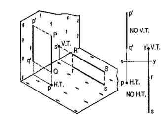
(i) A line PQ is perpendicular to the H.P. Its H.T. coincides with its top view which is a point. It has no V.T.
(ii) A line RS is perpendicular to the V.P. Its V.T. coincides with its front view which is a point. It has no H.T.
Hence, when a line is perpendicular to a plane, its trace on that plane coincides with its projection on that plane. It has no trace on the other plane.
|
Figure 27
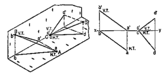
(i) A line AB has its end A in the H.P. and the end B in the V.P. Its H.T. coincides with the top view of A and the V.T. coincides with b' the front view of B.
(ii) A line CD has its end C in both the H.P. and the V.P. Its H.T. and V.T. coincide with c and c' (the projections of C) in xy. Hence, when a line has an end in a plane, its trace upon that plane coincides with the projection of that end on that plane.
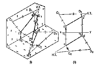
Methods of determining traces of a line:
|
Figure 28
Method I:
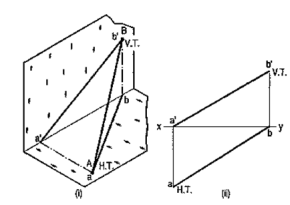
Fig. 28 (i) shows a line AB inclined to both the reference planes. Its end A is in the H.P. and 8 is in the V.P. a'b' and ab are the front view and the top view respectively [fig. 28 (ii)].
The H.T. of the line is on the projector through a' and coincides with a. The V.T. is on the projector through b and coincides with b'.
|
Figure 29
Let us now assume that AB is shortened from both its ends, its inclination with the planes remaining constant. The H.T. and V.T. of the new line CD are still the same as can be seen clearly in fig. 29 (i). c'd' and cd are the projections of CD [fig. 29 (ii)]. Its traces may be determined as described below.
(i) Produce the front view c'd' to meet xy at a point h.
(ii) Through h, draw a projector to meet the top view cd-produced, at the H.T. of the line.
(iii) Similarly, produce the top view cd to meet xy at a point v.
(iv) Through v, draw a projector to meet the front view c'd'-produced, at the V.T. of the line.
Method II:
|
Figure 30
c'd' and cd are the projections of the line CD [fig. 30 (ii)]. Determine the true length C1D1 from the front view c'd' by trapezoid method. The point of intersection between c'd'-produced and C1D1-produced is the V.T. of the line.
Similarly, determine the true length C2D2 from the top view ed. Produce them to intersect at the H.T. of the line.
Examples:
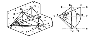
1. A line AB 50 mm long, has its end A in both the H.P. and the V.P. It is inclined at 30° to the H.P. and at 45° to the V.P. Draw its projections.
As the end A is in both the planes, its top view and the front view will coincide in xy.
|
Figure 31
(i) Assuming AB to be parallel to the V.P. and inclined at θ (equal to 30°) to the H.P., draw its front view ab' (equal to AB) and project the top view ab.
(ii) Again, assuming AB to be parallel to the H.P. and inclined at ϕ (equal to 45°) to the V.P., draw its top view ab1 (equal to AB). Project the front view ab'1.
ab and ab'1 are the lengths of AB in the top view and the front view respectively, and pq and rs are the loci of the end B in the front view and the top view respectively.
(iii) With a as center and radius equal to ab'1, draw an arc cutting pq in b'2. With the same center and radius equal to ab, draw an arc cutting rs in b2.
Draw lines joining a with b'2 and b2. ab'2 and ab2 are the required projections.
|
Figure 32
Fig. 32 shows in pictorial and orthographic views, the solution obtained with all the above steps combined in one figure only.
Plane figures or surfaces have only two dimensions, viz. length and breadth. They do not have thickness. A plane figure may be assumed to be contained by a plane, and its projections can be drawn, if the position of that plane with respect to the principal planes of projection is known.
In this chapter, we shall discuss the following topics:
1. Types of planes and their projections.
2. Traces of planes.
Planes may be divided into two main types:
(1) Perpendicular planes.
(2) Oblique planes.
Perpendicular planes:
These planes can be divided into the following sub-types:
(i) Perpendicular to both the reference planes.
(ii) Perpendicular to one plane and parallel to the other.
(iii) Perpendicular to one plane and inclined to the other.
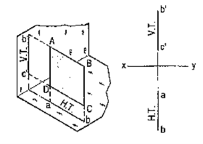
4.6.3 Perpendicular to both the reference planes (fig 1):
A square ABCD is perpendicular to both the planes. Its H.T. and V.T. are in a straight-line perpendicular to xy.
|
Figure 33
The front view b'c' and the top view ab of the square are both lines coinciding with the V.T. and the H.T. respectively.
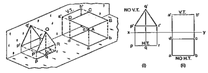
4.6.4 Perpendicular to one plane and parallel to the other plane:
a) Plane, perpendicular to the H.P. and parallel to the V.P. [fig. 12-2(i)]. A triangle PQR is perpendicular to the H.P. and is parallel to the V.P. Its H.T. is parallel to xy. It has no V.T.
The front view p'q'r' shows the exact shape and size of the triangle. The top view pqr is a line parallel to xy. It coincides with the H.T.
(b) Plane, perpendicular to the V.P. and parallel to the H.P. [fig. 12-2(ii)]. A square ABCD is perpendicular to the V.P. and parallel to the H.P. Its V.T. is parallel to xy. It has no H.T.
The top view abed shows the true shape and true size of the square. The front view a'b' is a line, parallel to xy. It coincides with the V.T.
|
Figure 34
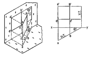
4.6.5 Perpendicular to one plane and inclined to the other plane:
A square ABCD is perpendicular to the H.P. and inclined at an angle φ to the V.P. Its V.T. is perpendicular to xy. Its H.T. is inclined at φ to xy.
Its top view ab is a line inclined at φ to xy. The front view a'b'c'd' is smaller than ABCD.
|
Figure 35
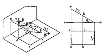
(b) Plane, perpendicular to the V.P. and inclined to the H.P. (fig. 12-4).
A square ABCD is perpendicular to the V.P. and inclined at an angle θ to the H.P. Its H.T. is perpendicular to xy. Its V.T. makes the angle e with xy. Its front view a'b' is a line inclined at θ to xy. The top view abed is a rectangle which is smaller than the square ABCD.
|
Figure 36
Fig. 36 shows the projections and the traces of all these perpendicular planes by third-angle projection method.
|
Figure 37
A solid has three dimensions, viz. length, breadth and thickness. To represent a solid on a flat surface having only length and breadth, at least two orthographic views are necessary. Sometimes, additional views projected on auxiliary planes become necessary to make the description of a solid complete.
This chapter deals with the following topics:
1. Types of solids.
2. Projections of solids in simple positions.
(a) Axis perpendicular to the H.P.
(b) Axis perpendicular to the V.P.
(c) Axis parallel to both the H.P. and the V.P.
3. Projections of solids with axes inclined to one of the reference planes and
parallel to the other.
(a) Axis inclined to the V.P. and parallel to the H.P.
(b) Axis inclined to the H.P. and parallel to the V.P.
4. Projections of solids with axes inclined to both the H.P. and the V.P.
5. Projections of spheres.
Solids may be divided into two main groups:
(1) Polyhedra
(2) Solids of revolution.
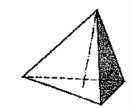
Polyhedra: A polyhedron is defined as a solid bounded by planes called faces. When all faces are equal and regular, the polyhedron is said to be regular. There are seven regular polyhedra which may be defined as stated below:
(i) Tetrahedron (fig. 1): It has four equal faces, each an equilateral triangle.
|
Figure 38
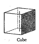
(ii) Cube or hexahedron (fig. 39): It has six faces, all equal squares.
|
Figure 39
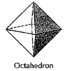
(iii) Octahedron (fig. 40): It has eight equal equilateral triangles as faces.
|
Figure 40
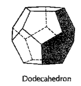
(iv) Dodecahedron (fig. 41): It has twelve equal and regular pentagons as faces.
|
Figure 41
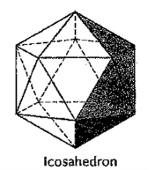
(v) Icosahedron (fig. 42): It has twenty faces, all equal equilateral triangles.
|
Figure 42
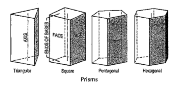
(vi) Prism: This is a polyhedron having two equal and similar faces called its ends or bases, parallel to each other and joined by other faces which are parallelograms. The imaginary line joining the centres of the bases is called the axis. A right and regular prism (fig. 43) has its axis perpendicular to the bases. All its faces are equal rectangles.
|
Figure 43
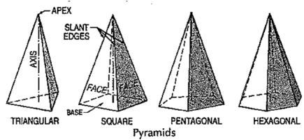
(vii) Pyramid: This is a polyhedron having a plane figure as a base and many triangular faces meeting at a point called the vertex or apex. The imaginary line joining the apex with the centre of the base is its axis.
A right and regular pyramid (fig. 43) has its axis perpendicular to the base which is a regular plane figure. Its faces are all equal isosceles triangles.
|
Figure 44
Oblique prisms and pyramids have their axes inclined to their bases. Prisms and pyramids are named according to the shape of their bases, as triangular, square, pentagonal, hexagonal etc.
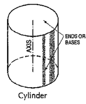
(i) Cylinder (fig. 45): A right circular cylinder is a solid generated by the revolution of a rectangle about one of its sides which remains fixed. It has two equal circular bases. The line joining the centres of the bases is the axis. It is perpendicular to the bases.
|
Figure 45
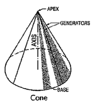
(ii) Cone (fig. 46): A right circular cone is a solid generated by the revolution of a right-angled triangle about one of its perpendicular sides which is fixed.
|
Figure 46
It has one circular base. Its axis joins the apex with the centre of the base to which it is perpendicular. Straight lines drawn from the apex to the circumference of the base-circle are all equal and are called generators of the cone. The length of the generator is the slant height of the cone.
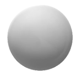
(iii) Sphere (fig. 47): A sphere is a solid generated by the revolution of a semi-circle about its diameter as the axis. The mid-point of the diameter is the centre of the sphere. All points on the surface of the sphere are equidistant from its centre.
|
Figure 47
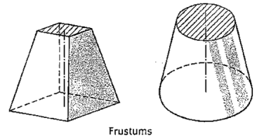
(iv) Frustum: When a pyramid or a cone is cut by a plane parallel to its base, thus removing the top portion, the remaining portion is called its frustum (fig. 48).
|
Figure 48
(v) Truncated: When a solid is cut by a plane inclined to the base it is said to be truncated.
Conversion of a pictorial view into orthographic views requires sound knowledge of the principles of pictorial projection and some imagination. A pictorial view may have been drawn according to the principles of isometric or oblique projection. In either case, it shows the object as it appears to the eye from one direction only. It does not show the real shapes of its surfaces or the contour. Hidden parts and constructional details are also not clearly shown. All these must be imagined.
For converting a pictorial view of an object into orthographic views, the direction from which the object is to be viewed for its front view is generally indicated by means of an arrow. When this is not done, the arrow may be assumed to be parallel to a sloping axis. Other views are obtained by looking in directions parallel to each of the other two axes and placed in correct relationship with the front view.
When looking at the object in the direction of any one of the three axes, only two of the three overall dimensions (viz. length, height and depth or thickness) will be visible. Dimensions which are parallel to the direction of vision will not be seen. Lines which are parallel to the direction of vision will be points, while surfaces which are parallel to it will be lines.
While studying a pictorial view, it should be remembered that, unless otherwise specified:
(i) A hidden part of a symmetrical object should be assumed to be like the corresponding visible part.
(ii) All holes, grooves etc. should be assumed to be drilled or cut right through.
(iii) Suitable radii should be assumed for small curves of fillets etc. An object in its pictorial view may sometimes be shown with a portion cut and removed, to clarify some internal constructional details. While preparing its orthographic views, such object should be assumed to be whole, and the views should then be drawn as required.
(i) It is comparatively easy to prepare a drawing from an actual object. The object is carefully examined and then placed in a suitable position for the front view. The front view of the object is selected in such a way that the maximum details of the object are visible so that the minimum dotted lines are required.
(ii) All the necessary views are then sketched freehand in a sketch book or on a pad.
(iii) Measurements of all its details and overall sizes are taken and inserted in the views, along with important notes and instructions.
(iv) Finally, a scale-drawing is prepared from these sketches.
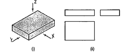
A pictorial view of a rectangular plate is given in fig. 49(i). Its front view when seen in the direction of the arrow X, side view from the left, i.e. in the direction of the arrow Y and the top view in the direction of arrow Z, are shown in fig. 49(ii).
|
Figure 49
|
Figure 50
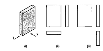
The same plate is shown in fig. 50 (i) with its longer edges vertical. Its front view looking in the direction of the arrow X, side view from the left and the top view are shown in fig. 50 (ii). These three views are similar in shape and size to the views shown in fig. 49 (ii). Only their positions and conditions have changed. Even when the front view is drawn looking in the direction of the arrow Y [fig. 50 (iii)], the three views remain similar in shape and size.
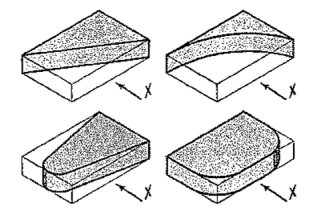
The same plate is shown cut in various shapes in fig. 51. The front view and the side view in each case will be the same as in fig. 49 (ii). The changed shapes will be seen in the top view of each plate. If these plates are kept in the position shown in fig. 50 (i), the front view in each case (looking in direction of the arrow X) will show a different shape, while the side view and the top view will be rectangles.
|
Figure 51
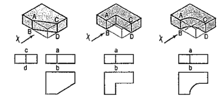
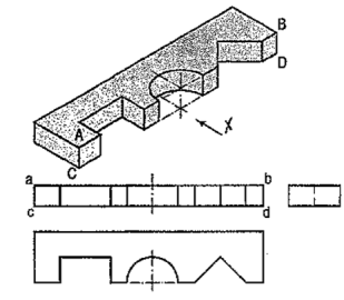
A plate cut in three different ways is shown in fig. 52. The front view in each case is the same, viz. a rectangle with a vertical line ab for the edge AB. The side view from the right in each case will be a rectangle with a vertical line cd for the edge CD. The top view in each case shows the shape of the cut.
|
Figure 52
In the front view of the plate having different shapes of grooves (fig. 53), two vertical lines are drawn for the edges of rectangular as well as semi-circular grooves.
|
Figure 53
In case of the triangular groove, three vertical lines are required. Although edges AB and CD are cut, they are continuous lines ab and ed. In the top view, shapes of the grooves are seen. The grooves are not visible in the side view and hence, they are shown by a hidden line.
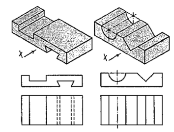
Two plates having grooves in upper and lower surfaces are shown in fig. 54. The shapes of the grooves are seen in the front views. In top views, two lines for the edges of rectangular as well as semi-circular grooves are drawn. For the triangular grooves, three lines are required. The tapered groove in the bottom surface is assumed to be cut throughout the width of the plate. It is not visible from above and hence; its four edges are shown by four hidden lines in the top view. In their side views, each groove should be shown by a horizontal hidden line. Therefore, the side view in this case is not necessary.
|
Figure 54
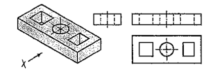
A plate having holes of different shapes is shown in fig. 55. These shapes are seen in the top view. Holes are assumed to be cut or drilled right through. They are shown by hidden lines in the front and the side views. Here also the right-side view is not necessary.
|
Figure 55
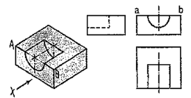
The semi-circular groove in the block shown in fig. 56 does not extend up to the opposite surface. Therefore, although the edge AB is broken, ab is a continuous line in the front view. The groove is shown by hidden lines in the side view. In the top view it is drawn as a rectangle.
|
Figure 56
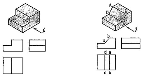
Fig. 57 shows a block in the shape of steps, along with its three views. In fig. 58, its face ABCD is inclined. Hence, in the top view, two lines ab and cd are drawn for that face.
|
Figure 57 Figure 58
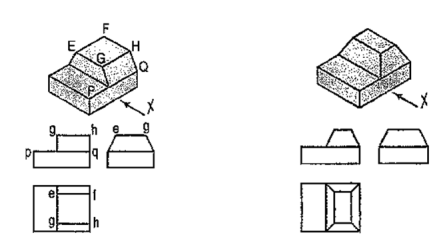
The front and back faces of the upper step are shown inclined in fig. 59. Their inclinations are shown in the side view. In the front view, the line pq for the edge PQ is drawn. In the top view, lines ef and gh for edges ff and CH are shown.
In fig. 60, all the four side-faces of the upper step are inclined. Their inclinations are seen in the front view and in the side view. In the top view, two rectangles are seen for the upper step. Lines (for the four sloping edges) joining the corners of the rectangles should also be shown.
|
Figure 59 Figure 60
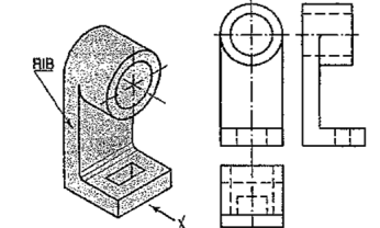
A casting having a hollow cylinder supported by a vertical rib is shown in fig. 61. The width of the rib is equal to the diameter of the cylinder. Hence, in the front view, vertical lines for the rib are tangential to the circle for the cylinder.
In the side view, the line showing the thickness of the rib vanishes just at the centre line. The rib is not visible when seen from top. Hence, it is shown by a hidden line in the top view. Note that the third view (top view) is a 'necessary' view to show the shape of rectangular slot.
|
Figure 61
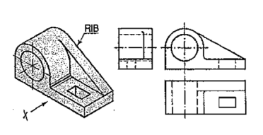
In the bearing block shown in fig. 62, the line for the rib is inclined and tangent to the semi-circle in the front view. Vanishing points for the lines for the rib in the side view and the top view are obtained by projecting the tangent-point from the front view.
|
Figure 62
From the above discussion, the following important points are to be noted:
(i) An object can be observed from six sides such as
(a) front side
(b) back side
(c) left-hand side
(d) right-hand side
(e) top side and
(f) bottom side.
It is not necessary to draw all the possible six views to describe completely the shape of the object. In practice, only those views which are necessary to describe the shape of the object should be drawn.
The view should be selected in such a way that minimum dotted lines are necessary to show internal details. The object which has both the right-hand side and left-hand side symmetrical shape requires only two views.
One of the views must be such that it completely describes the shape of the object. Refer fig. 61
(ii) Three views are necessary for the object which is not symmetrical. Refer fig. 58 and fig. 60.
(iii) The view should not be drawn out of place. That is the side view and top view are not aligned with the front view. This should be avoided.
(iv) Dotted lines must be drawn correctly as shown in table 1. Incorrect points are indicated by circle.
Table 1
|
Figure 63
(v) (a) When a visible line coincides with either a dotted line or a centre line, the visible line is shown and a centre line is extended beyond the outlines of the view.
(b) When a section-plane line coincides with a centre line, the centre line is shown and the section-plane line is drawn outside the out-lines of the object at the ends of centre line by thick dashes.
(c) When a dotted line coincides with the centre line, the dotted line should be shown.
|
2.
|
3.
|
References:-
1. Bhatt, N. D. and Panchal, V. M., (2016), “Engineering Drawing”, Charotar Publication, Anand, India
2. K. Venugopal, K, (2015), “Engineering and Graphics”, New Age International, New Delhi
3. Jolhe, D. A., (2015), “Engineering Drawing with introduction to AutoCAD”, Tata McGraw Hill, New Delhi
4. Rathnam, K., (2018), “ A First Course in Engineering Drawing”, Springer Nature Singapore Pte. Ltd., Singapore
