UNIT 2
INTRODUCTION TO THERMAL ENGINEERING
2.1.1 Definition of Thermodynamics
- It is a Branch of science which deals with study of energy transfer and its effects on properties of system and surrounding . OR
- Thermodynamics is a science which deals with the relations among heat, work and properties of system which are in equilibrium. It describes state and changes in state of physical systems.
2.1.2 Applications of thermodynamics
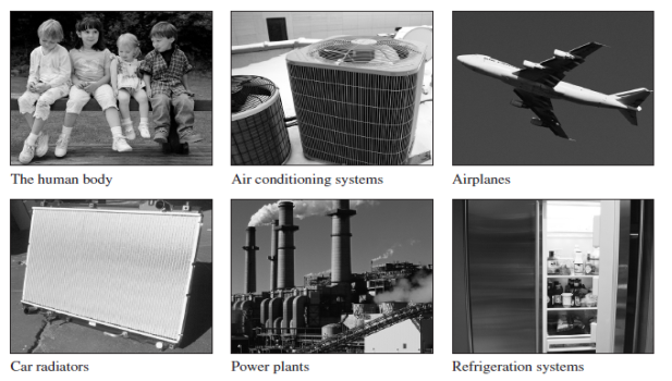
- Various Applications of thermodynamics are IC Engine, Steam Engine, Nuclear Power Plant, Pumps, Refrigerator, AC, Human Body etc.
|
Fig: Examples of thermodynamics systems
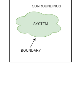
- Thermodynamic System:A quantity of matter or fixed mass in region in space chosen for study of heat and work transfer is known as thermodynamic system.
- Surroundings: Mass or region outside the system is called as surrounding. Everything outside the system can be called as surrounding.
- Boundary: It is the real or imaginary surface that separates the system from the surroundings. Boundary can be fixed or movable.
- Universe: A system & its surroundings together are called the universe.
Fig: System Surrounding and Boundary
|
2.1.3 Types of Thermodynamics Systems
- Depending upon the mass and energy transfer, system can be classified into 3 types.
- Closed System
- Open System
- Isolated System
1) Closed system
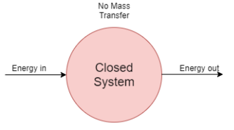
- A system in which only energy transfer takes place across its boundary and mass remains constant is called closed system.
- In the closed system, only energy transfer takes place across the boundary in the form of work and heat with the surrounding.
- It consists of a fixed amount of mass. Mass can NOT cross the boundary.
- Energy can cross the boundary. Volume does not have to be fixed
- An example of this system is mass of gas or vapour contained in a piston cylinder arrangement.
|
Fig: Closed system with fixed boundary
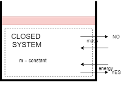
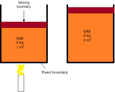
- Consider the piston-cylinder device shown in Fig. below. Let us assume that we want to find out what will happen to the enclosed gas when it is heated. As our attention is on the gas, it is our system. The inner surfaces of the piston and the cylinder forms the boundary.
|
Fig: Closed system with moving boundary
- Let the gas is being heated by the burner as shown. Thus energy in the form of heat is crossing the boundary and raises pressure and temperature of gas. Due to this, some part of the boundary (the inner surface of thepiston, in this case) may move upward.
- Here no mass of gas is crossing this boundary, thus it is a closed system.
- Everything outside the gas, including the piston and the cylinder, is the surroundings.
- Other example of closed system is vapour compression refrigeration system.
2) Open System
- A system in which mass transfer along with energy transfer takes place across its boundaries is called as open system.
- Usually it involves a device through which mass flows. Here Mass and energy can cross the boundary. It can be fixed in space or it can have a moving boundary.
- Example – Turbine. High pressure Steam enter into turbine & low pressure steam leave the turbine.
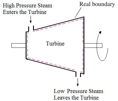
Fig: Open system
- As shown in fig above, Steam can enter and leave the cylinder, as well as due to expansion of high pressure high temperaturesteam,shaft also rotates and low pressure low temperature steam leaves the turbine. Thus both mass and energy transfer takes place in above system. So it is an open system.
- Other examples of open system are nozzle, Air Compressor, water heater etc.
3) Isolated System
- If there is no mass & energy transfer between the system & surroundings, a system is said to be an isolated system. It is aSpecial case of a closed system.
- In this system, No energy and mass is allowed to cross the boundary as shown in fig below.
- Example: Perfectly insulated containers likes thermos flask.
2.1.4 State
- It is the condition of body or object when all the properties have fixed values.
- At a given state, all the properties of a system havefixed values. If the value of even one property changes, the state will changeto a different one i.e. when any of the property changes, then the state of the object also changes.
2.1.5 Property
- Any characteristic of a system is called a property. There are two types of properties.
- Intensive Property
- The properties which are independent of the mass of the system are called.
- Independent of the size of the system. Ex. temperature, pressure, viscosity
2. Extensive Property
- These are the Properties of system which depends on the size (or extent) & mass of the system.
- Ex. Mass, length volume, total energy.
- Specific Properties: Extensive properties per unit mass. Ex. Specific volume, specific energy
2.1.6 Important Terms
- Energy – Capacity to do work
- Internal energy- The internal energy present in a system due to molecular motion , arrangement of atomic structure & its chemical composition
- Potential energy – Energy of position of mass. = m.g.h
- Kinetic energy- Energy due to motion of mass. =

2.1.7 Thermodynamic Equilibrium
- Thermodynamics deals with equilibrium states. Equilibrium is nothing but a state of balance.
- In an equilibrium state there will not be unbalancedpotentials (or driving forces) within the system. A system in equilibriumexperiences no changes when it is isolated from its surroundings.
- System is not in thermodynamic equilibrium unless the conditions of all the relevant types of equilibrium are satisfied.
- Thus when a system or object satisfies the conditions of
- Mechanical Equilibrium (No Unbalanced pressure forces)
- Thermal Equilibrium (Equal temperature)
- Chemical Equilibrium (No chemical reaction within the system),
then the system or object is said to be in Thermodynamic Equilibrium.
- Mechanical equilibrium is related to pressure, and a system is in mechanical equilibrium if there is no change in pressureat any point of the system with the time.
- If temperature is same through the system then it is said to be in thermal equilibrium
- A system is in chemical equilibrium if its chemicalcomposition does not change with time, that is, no chemical reactions occur.
2.1.8 Process and path
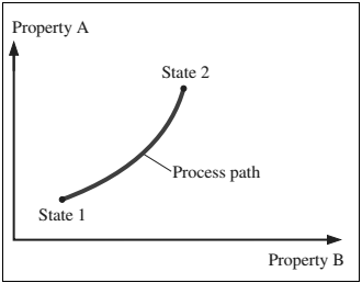
- When a system undergoes any change from one equilibrium state toanother equilibrium state, then this change is called a process.
|
Figure: A process between states 1 and 2 and the process path
- The series of states through which a system passes during a process is called the path of the process.
2.1.9 Cycle
|
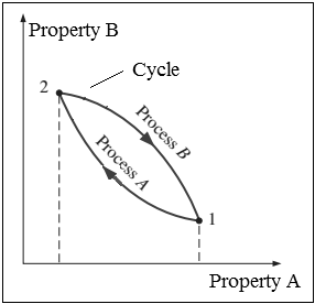
- Any process (which the system undergoes) having the initial and final states identical is called as cycle. When any system undergoes a cycle, then it returns to its initial state at the end of the process. That is, for a cycle the initial and final states are same.
LAWS OF THERMODYNAMICS
- Statement -: ‘It states that if two bodies (or systems) are in thermal equilibrium with a third body (system) separately, then those two bodies are also in thermal equilibrium with each other. i.e. all three systems are in thermal equilibrium with each other.’
- Observation-: When a body is brought into contact with another body that is at a different temperature, heat is transferred from the body at higher temperature to the one at lower temperature until both bodies attain the same temperature (thermal equilibrium).
|
Fig: Representation- Zeroth law of thermodynamics
- Consider that there are three bodies A, B, C respectively having temperature T °C .
Let body A is in thermal equilibrium with body C as both have same temperature T °C.
Let body B is in thermal equilibrium with body C as both have same temperature T °C.
Now, since both bodies A & B are having temperature T °C as that of temperature of body C, then Both A and B are also in thermal equilibrium with each other.
Heat:
- Heat is the form of energy which is transferred, without transfer of mass, from one body to another body from higher temperature to lower temp. It is denoted by Q.
- Sign convention – Heat transfer to the system from surrounding is considered +Ve& vice versa.
Work:
- Work is also a transient form of energy which is observed when it crosses the boundaries of the system without transfer of mass.
Enthalpy:
- H= U + PV
- H is called specific enthalpy & U represent the specific internal energy
- H is an extensive property. The combination of (u + PV) plays an important role in analyzing the problems in case of open systems where matter crosses the boundary of the system.
- Statements of first law of thermodynamics:
- When a closed system undergoes a thermodynamic cycle then the net heat supplied to the system from the surroundings is equal to net work done by the system on its surroundings. OR
- When closed system executes a cyclic process, the algebraic sum of work transfers is proportional to the algebraic sum of heat transfer.

OR
- Energy can neither be created nor destroyed; but, it can be converted from one form to another form. OR
- All the forms of energies are equivalent as well as convertible. Both heat and work are mutually convertible. OR
- No machine can produce energy without corresponding expenditure of energy, i.e., it is impossible to construct a perpetual motion machine of first kind (PMM-1).
- PMM-1 is a machine or device which violates or disagrees with first law of thermodynamics.
- Limitation of First Law of Thermodynamics
- First law of thermodynamics states about energy balance in a process but it is silent about the direction of process.
- The energy transfer always takes place in a particular direction, 1st law doesn’t give the direction of flow of energy. Heat transfer takes place from hot to cold body only.
- For ex: A cup of hot coffee left in a cooler room eventually cools off. The reverse of this process coffee getting hotter as a result of heat transfer from a cooler room does not take place.
- Water flows downhill where by potential energy is converted into K.E. Reverse of this process does not occur in nature.
- All processes involving conversion of heat into work and vice versa are not equivalent. The work can be fully converted into heat, but conversion of all heat into work is not possible.
- For ex: Consider heating of a room by passage of electric current through an electric resistor. Transferring of heat from room will not cause electrical energy to be generated through the wire.
2.1.10 Basic terms
- Thermal Reservoir/ Heat Reservoir:
- A thermal reservoir is defined as the source of infinite heat energy.
- Finite amount of heat absorbed or heat rejected from the heat reservoir will not affect its temperature i.e. the temperature of heat reservoir remains constant.
- The atmosphere and sea are examples of thermal reservoirs.
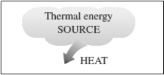
- Heat Source
- A heat reservoir that supplies heat energy continuously without affecting its own temper is called a heat source.
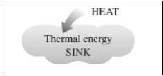
- Heat Sink
- A heat reservoir that Absorbs heat energy continuously without affecting its own temper is called a heat sink.
- For example, atmospheric air is a source for heat pumps and a sink for air conditioners
|
Fig: Source and sink
2.1.11 Heat Engine
- Heat Engine is a device which operates in a cycle and produces the work continuously at the expense of heat input supplied to it.
- Examples- steam engine, steam turbine power plants, I C engines like petrol & diesel engines, gas turbines etc. A block diagram of heat engine is shown below.
- Heat Engine working in cycle, receives or absorbs heat Q1 from heat source which is having temperature T1(or TH)& produces the mechanical work W.
- The remainder of heat energy Q2 is rejected to heat sink which is having temperature T2 (or TL).
- Here, Source Temperature T1(or TH)> Sink temperature T2 (or TL)
 Fig: Heat Engine


- From First Law of Thermodynamics,
Work Output of Engine = Heat Absorbed by Engine – Heat Rejected by Engine

- Heat Rejected by Engine is,

- Thermal efficiency of a Heat Engine:
- Thermal efficiency is the measure of performance of the heat engine.
- Thermal efficiency is the ratio of work output produced by the engine to the Energy input given to the engine.
- The efficiency in general can be expressed as

- Thus an efficiency of heat engine is always less than 1.
2.1.12 Heat Pump and refrigerator
- Both Heat pump and refrigerator are reversed heat engine.
- Example: Refrigerator- Summer air conditioning system
Room Heater: Winter air conditioning system
- Based on the objective, heat pump can be used as room heater or refrigerator or AC.
- Heat Pump
- Heat pump is a device (which operates in a cycle) removes the heat from a low temperature Body (heat sink) & rejects it to a body at high temperature (heat source) at the expense of external work supplied to it.
- In heater or heat pump main purpose is to maintain high temperature in an enclosed space, so it absorbs the heat from surrounding environment and gives it to enclosed space. Thus here, desired effect or the output of heat pump is heating effect produced by it.
- A block diagram of heat pump is shown below.

Fig:Heat Pump
- When work input W is supplied to heat pump working in cycle, itabsorb or removes the heat Q2 from heat Reservoirwhich is at low temperature T2 (or TL). This low temperature Heat reservoir can be considered as AMBIENT OR SURROUNDING ENVIRONMENT.
- The Heat Pump then rejectsQ1 amount of heat energy to the high temperature heat reservoir which is having temperature T1 (or TH). This high temperature Heat reservoir can be considered as ENCLOSED SPACE.This heat rejected or supplied by heat pump is the desired output or desired HEATING effect produced by it inside the enclosed space.
Here, Temperature T1(or TH)>Temperature T2 (or TL)
- Thus by continuously supplying or rejecting the heat to enclosed space, heat pump maintains the higher temperature insideto enclosed space as compared to surrounding.
- In case of Heat pump,
- The objective of the system is to deliver heat energy at higher temperature T1 (Just likeheatinga room or enclosed space in winter).
- Then temp. T1(at which heat is rejected or supplied) corresponds to enclosed space and the temp. T2(at which heat is absorbed) corresponds to ambient temperature or surrounding environment.
|
- From First Law of Thermodynamics,
Work Inputto Heat Pump = Heat Rejected by Heat Pump - Heat Absorbed by Heat Pump

- Work Output by heat pump or Heat Rejected by Heat Pump or Heating Effectproduced is,

- Efficiency of a Heat Pump is expressed in terms of Coefficient Of Performance (C.O.P.)
- Coefficient of Performance (C.O.P.) is the measure of performance of the heat pump.
- Coefficient of Performance (C.O.P.) of Heat pump is the ratio of desired work output or desired heating effectproduced by heat pump to the Energy input given to heat pump.
- Coefficient of Performance (C.O.P.) in general can be expressed as

- Thus COP of heat pump is always greater than 1.
2. Refrigerator
- Refrigerator is a device (which operates in a cycle) removes the heat from a low temperature Body (heat sink) & rejects it to a body at high temperature (heat source) at the expense of external work supplied to it.
- In refrigerator main purpose is to maintain low temperature in an enclosed space, so it absorbs the heat from enclosed space and rejects it to surrounding Environment. Thus here, desired effect or the output of refrigerator is cooling effect produced by it.
- A block diagram of refrigerator is shown below.

Fig: Refrigerator
- When work input W is supplied to refrigerator working in cycle, it absorbs or removes the heat Q2 from heat Reservoirwhich is at low temperature T2 (or TL). This low temperature Heat reservoir can be considered as ENCLOSED SPACE.This heat absorbed or removed by refrigerator is the desired output or desired COOLING effect produced by it inside the enclosed space.
- The Refrigerator then rejects Q1 amount of heat energy to the high temperature heat reservoir which is having temperature T1 (or TH). This high temperature Heat reservoir can be considered as AMBIENT OR SURROUNDING ENVIRONMENT.
Here, Temperature T1 (or TH) > Temperature T2 (or TL)
- Thus by continuously absorbing or removing the heat from enclosed space, Refrigerator maintains the lower temperature insideto enclosed space as compared to surrounding.
- In case of refrigerator,
- The Objective of the system is to produce cooling effect at low temperatureT2 (Just like removing the heat from a room or enclosed space in summer by using AC or removing the heat from enclosed space by using fridge).
- Then temp. T1(at which heat is rejected) corresponds to ambient temperature or surrounding environment and the temp. T2 (at which heat is absorbed or removed) corresponds to enclosed space.
|
- From First Law of Thermodynamics,
Work Input to Refrigerator = Heat Rejected by Refrigerator - Heat Absorbed by Refrigerator

- Work Output by Refrigerator or Heat Absorbed (removed) by Refrigerator or Cooling Effect produced by Refrigerator is also called as Refrigeration Effect (R.E.). It is given by the relation,

- Efficiency of a Refrigerator is expressed in terms of Coefficient Of Performance (C.O.P.)
- Coefficient of Performance (C.O.P.) is the measure of performance of the Refrigerator.
- Coefficient of Performance (C.O.P.) of Refrigerator is the ratio of desired work output or desired cooling effect or Refrigeration Effect produced by Refrigerator to the Energy input given to Refrigerator.
- Coefficient of Performance (C.O.P.) in general can be expressed as
|
- Thus COP of Refrigerator is always greater than 1.
2.1.13 Relation between COP of Heat pump and COP of refrigerator
- Coefficient of performance of heat pump and refrigerator is expressed in terms of COP.
From 1st law,
(C.O.P) of Heat pump: (C.O.P) of Refrigerator: Now,
|
COP of heat pump is always more than that of refrigerator.
2.1.14 The Kelvin-Planck Statement:
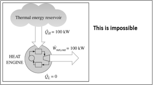
- It is impossible to construct a heat engine operating in a cyclic process, whose sole function is to transfer theentire heat received from a single heat reservoir & its conversion into equal amount of work.
|
Fig: Heat engine violates the Kelvin – Planck statement
2.1.15 Clausius Statement
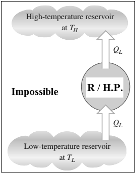
- It is impossible to construct a device (heat pump or refrigerator) operating in a cyclic process,whose sole function is to transfer the heat from a low temperature heat reservoir to a higher temperature heat reservoir without any supply of input external work to the device.
|
- Though heat energy cannot flow from a body at lower temperature to a body at higher temperature, however such a transfer of heat can be achieved in practice by providing some work energy to the system e.g. refrigerator/heat pump as shown in above figure.
- Heat is the form of energy which can be transferred from one system/object to another system/object across their boundaries due to the temperature difference between two systems.
- Presence of temperature difference is the basic requirement for heat transfer. When two bodied are at same temperature then, there can be no net heat transfer between two.
- The temperature difference is the driving force for heat transfer.
- Increase in magnitude of the temperature gradient (the temperature difference per unit length or the rate of change of temperature) in that direction increases the rate of heat transfer.
- Various Application Areas of Heat Transfer are
- The human body
- Air-conditioning systems
- Cooling of Printed Circuit boards of electronic components
- Car radiators
- Power plants
- Refrigeration systems
- Engine cylinder
- Heat exchanger, boiler,
- \Condenser, cooling tower, solar collectors
- Modes of heat transfer are
- Conduction
- Convection
- Radiation
- In practical/physical problems, rate of heat transfer is controlled by combined effect of all three modes i.e. Conduction, convection, Radiation
- But we have to identify major mode of heat transfer so as to neglect other modes which are less dominant.
2.1.16 Conduction
- Conduction is the transfer of heat energy from one particle of a
substance to the adjacent another particle of same substance without appreciable movement of molecule or the particles. - Here one particle will be at higher energy level, i.e. it will be more energetic and another particle will be at lower energy level, i.e. it will be less energetic particle.
- Conduction can take place in solids, liquids, or gases.
- In liquids and gases, conduction is mainly due to the collisions and diffusion of the molecules during their random motion or movement.
- In solids, Conduction take place due to vibrations of the molecules in a lattice and the energy transport by free electrons.
- Rate of heat transfer depends upon
- Geometry of Medium
- It’s thickness
- Temperature Difference across medium.
Fourier’s Law of Heat Conduction
- It states that, therateof heat conduction or heat flow through a simple homogeneous solid layer of any material is directly proportional to the cross sectional area of layer (heat transfer area) measured normal to the direction of heat flowand the temperaturegradient across the layer in the direction of heat flow. OR
- It states that, the rate of heat conduction or heat flow through a simple homogeneous solid layer of any material is directly proportional to the cross sectional area of layer (heat transfer area) measured normal to the direction of heat flow and the temperature difference across the layer in the direction of heat flow but is inversely proportional to the thickness of the layer.
- Temperature difference across the layer is to be measured in the direction of heat flow.
- Rate of Heat Transfer
- Mathematically,
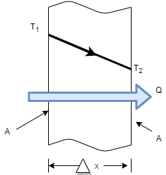
|
- Consider steady heat conduction through a large plane wall of thickness
 and area A, as shown in Figure.
 - The temperature difference acrossthe wall is


Where k = constant of proportionality = coefficient of thermal conductivity of material
- As heat always flows from higher temp to lower temp.

- Thus
 is negative i.e. temperature gradient in the direction of heat flow is negative because temperature decreases with x.
 - So by introducing negative sign in above equation heat transfer in the positive x direction is always a positive quantity.

Where unit of kis 
Q = Heat transfer rate by conduction in watt (J/sec)
A = Cross sectional Area of heat flow normal to the direction of heat flow ( )
)
 = Temperature difference between two faces of the solid body or layer (
 )
)
 = Thickness of solid body or layer (m)
- Heat Flux
Heat Transfer Rate per unit area is call as Heat Flux. It is denoted by ‘ q ’.

- When
 , Above equations reduces to differential form.

- Thermal Resistance to heat flow

- Thermal conductivity of material(k):
It is the ability of a material to conduct heat through it.
The rate of heat transfer through a unit thickness of the material per unit area perunit temperature difference.
2.1.17 Convection
- Convection is the process of heat energy transfer between a solid surface and the
adjacent liquid or gas that is in motion. - Faster the fluid motion, the greater will be the convection heat transfer.
- It involves the combined effects ofconduction and fluid motion.
- In the absence of any bulk fluid motion, heat transfer between a solid surface and the adjacent fluid is purely by conduction.
- To understand convection heat transfer, consider the hot vertical wall which is in contact with air as shown in figure.
|
- As the time elapsed, the layer cold air which is contact with hot vertical wall surface is heated by conduction of heat through wall surface to air in contact.
- Due to heating of air, density of air decreases, it causes the heated air to move up. This air is replaced by fresh cold air.
- This process continues and sets up natural convection currents. Here the circulation of fluid (air) takes place due to natural difference in densities of hot and cold fluid. Thus it is known as natural convection.
- To improve rate of convection heat transfer, if external force like fan, blower is used to cause the fluid motion, then it is known as forced convection heat transfer.
|
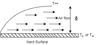
- Convection Heat Transfer Coefficient
|
- As shown in above figure, the fluid (air) flow (natural or forced) is shown in contact with hot surface.
- In this case near the surface, there exists the fluid film of thickness
 .
. - In this fluid film, the temperature of fluid or air near the hot surface equal the surface temperature.
- As we move away from the hot surface, this fluid temperature varies towards outer film.
- At the hot surface,

- At the fluid film away from hot surface,

- Let

Then, Convection Heat Transfer Coefficient is defined as, the ratio of thermal conductivity of the fluid film to its thickness.
|
- As
 decreases with the increase in fluid velocity due to forced convection, the value of h i.e. Convection Heat Transfer Coefficientis more for forced convection than by natural convection.
Newton’s Law of Cooling
- It states that rate of Heat Transfer by Convection is directly proportional to surface area normal to the direction of heat flow and the temperature difference between the wall surface and fluid flow.
- Mathematically,

Where,
h = convectionHeat transfer coefficient in 
Q = Heat transfer rate by convection in watt (J/sec)
A = Surface Area of heat transfer normal to the direction of heat flow ( )
)


2.1.18 Radiation
- Radiation is the energy emitted by matter in the form of electromagnetic waves (or photons) as a result of the changes in the electronic configurationsof the atoms or molecules.
- Unlike conduction and convection, the transfer ofenergy by radiation does not require the presence of an intervening medium.
- The transfer ofenergy by radiation is fastest (at the speed of light) and can take place in vacuum also.
- The intensity of the thermal radiation emitted by the body depends upon the nature of the body and its temperature.
- Out of the total radiations falling on the body,
- Fraction of the energy is reflected by the body
 .
. - Fraction of the energy is absorbed by body
 .
. - Remainder of the energy is transmitted through the body at the surface
 .
. 
- Fraction of the energy is reflected by the body
- Black Body
- The body which absorbs all the radiations falling on it is called asBlack Body. Black body is also the best emitter of the radiations.

- White Body
- The body which reflects all the radiations falling on it is called aswhite Body. Black body is also the best emitter of the radiations.

- Emissive Power (E)
- It is the radiation energy emitted by the body per unit area per unit time
- Emissivity (
 )
)- It is the ration Emissive Power of any surface or body to the Emissive Power of black surface or body. Its value lies between 0 and 1.
Stefan–Boltzmann law
- It states that Emissive Power of black surface or black body is directly proportional to fourth power of its temperature.
- For Black Body,

- For area of surface =

- For Black Body,

Where,
Q= Rate of heat energy in watt
As = Surface area in 
- Then Heat Flux is,

Where, 

- For Gray Body,

2.1.19 Classification of Boilers:
- Depending upon the relative position of Water and Flue gases:
- Water Tube Boiler
- Smoke Tube Boiler
- Depending upon the Position Furnace:
- Internally Fired Boiler
- Externally Fired Boiler
- Depending upon the Position of Axis of the Boiler:
- Vertical Boiler
- Horizontal Boiler
- Depending upon the Service:
- Stationary Boiler
- Portable Boiler
5. According to the Method of Circulation of Water and Steam:
- Natural Circulation
- Forced Circulation
6. According to the Pressure of Steam Generated:
- Low Pressure (pressure of steam below 80 bar)
- High Pressure (80 bar &above pressure of steam )
7. According to Nature of Draught Employed
- Natural or Chimney Draught
- Artificial Draught
2.1.20 FIRE TUBE BOILER:
- In fire tube or smoke tube boilers, the flue gases pass through the tubes which are surrounded by the water in the boiler shell. Ex. Cochran Boiler, Lancashire Boiler
Cochran Boiler
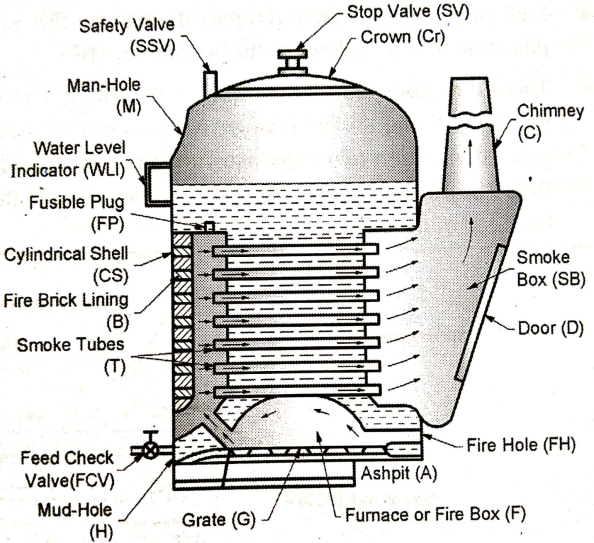
- Cochran boiler is a low pressure, vertical, internally fired, fire tube boiler in which the flue gases from the furnace (F) are passed through a number of small smoke tubes (T), surrounded by water, as shown in Fig. below.
|
Fig: Fire tube (Cochran) boiler
- The heat energy of the flue gases is transferred to the surrounding water in the cylindrical shell (CS). Finally, the flue gases from the smoke box (SB) are discharged to the atmosphere through the chimney (C).
- Various parts of Cochran boiler
- Furnace (F)
- Smoke box (SB)
- Chimney (C)
- Steam Stop valve (SV)
- Safety valve (SSV)
- Manhole (M)
- Water level indicator (WLI)
- Fusible plug (FP)
- Feed-check valve (FCV)
- Mud hole (H)
- Cylindrical shell (CS)
- Grate (G)
- Fire tubes (T)
- Ash pit (A)
2.1.21 WATER TUBE BOILER:
- In these, contrary to the smoke tube boilers, the water flows in the tubes and the hot gases are passed over thetubes.
- These types of boilers are useful for large amount ofsteam generation at high pressures due to low water to high flue gases ratio. Ex. Babcock Wilcox boiler.
Babcock Wilcox Boiler
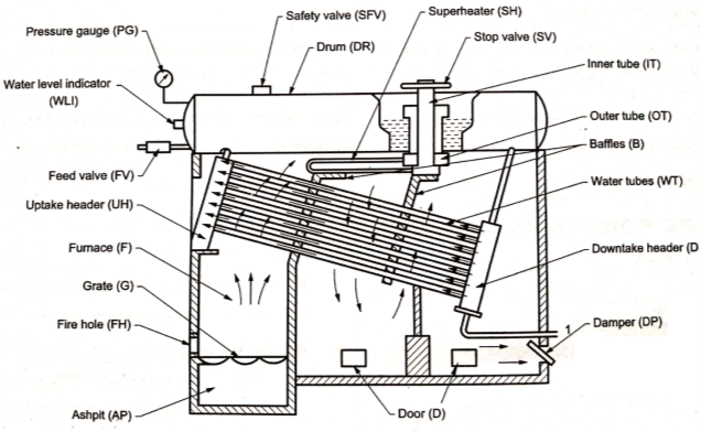
|
Fig: Water tube (Babcock Wilcox) boiler
- This is one of the important type of a water tube boiler used in the power houses for power generation as shown in above Fig.It consists of number of inclined water tubes (WT) connected between the uptake header (UH) and the down take header (DH).
- Whole combustion chamber is divided into number of parts with the help of baffles (B). Hot gases first move from the furnace (F) upwards between the water tubes and then move downward and upwards between the baffles over the tubes and finally these are exhausted to the chimney through the damper (DP).
- The dampers regulate the amount of flue gases and thus the supply of air to the grate. Doors (D) are provided for a man to enter in the boiler for cleaning and repairing purposes.
- The feed water enters the front of the drum (DR) and travels to the back part of the drum and then descends through the vertical tube to the down take header.
- From here the water enters into the water tubes to the uptake header and then again to the drum. The water tubes near the uptake header are in contact with the hotter flue gases compared to the portion near the down take header due to which the water in the uptake header rises due to decreased density and enters the drum which is replaced by the colder water from thedowntake header.
- Water continues to circulate like this till it is evaporated. This type of circulation of water occurring due to density difference is called free circulation. The superheating of steam is done in the superheater(SH). It consists of large number of steel tubes.
- Wet steam from the boiler drum enters in the outer tube (OT), then passes into the superheated tubes and during its passage it gets further heated up. Superheated steam now enters into the inner tubes (IT) and from here it iswithdrawn through a stop valve (SV).
- The boiler also has its usual mountings like pressure gauge (PG), safety valve (SFV), water level indicators (WLI), feed valve (FV) etc.
2.1.22 Advantages of Boilers:
- Highly compact, less space is required
- Lower operating cost
- Proven designs
- Shorter installation time
- Requires less fuel and electric supply
- Higher efficiency
- No Induced Draught fan is required
- The entire unit is mostly fabricated in the factory itself.
2.1.23 Disadvantages of Boilers:
- Lower reserve of water means a more efficient water level control is required
- High quality feed required
- little allowance to corrosion
- From the furnace combustion side, required time to fill water is longer than to increase temperature and pressure.
- The efficiency of heat transfer (heat transfer efficiency) is bad enough because of the heat exchanger does not use thermal radiation.
Heat Engine is a deviceused to convert heat energy (obtained by burning chemical fuel) into mechanical energy. Heat engines burns a fuel to create heat energy, which is then covered into mechanical power in the form of rotations.
2.1.24 Classification of Heat Engine
A) External Combustion Engine
B) Internal Combustion engine
- According to number of strokes
- Two stroke engine
- Four stroke engine
- According to number of Cylinder
- Single Cylinder Engine
- Multi-Cylinder Engine
- According to Fuel Used
- Petrol Engine’
- Diesel Engine
- CNG Engine
- According to method of ignition
- Spark Ignition Engine (S. I. Engine)
- Compression Ignition Engine (C. I. Engine)
- According to Cylinder arrangement
- V Cylinder Engine
- Inline Cylinder Engine
- According to Working Cycle
- Otto Cycle Engine
- Diesel Cycle Engine
- According to Cooling Method
- Air Cooled Engine
- Liquid Cooled Engine
2.1.25 Terminology Used in I.C. Engines
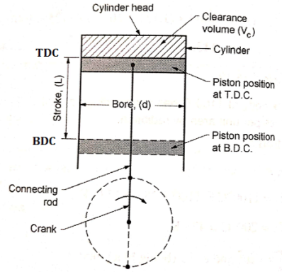
|
- Bore: It is the inside diameter of the cylinder.
- Stroke: It is the maximum distance travelled by the piston in the cylinder in one direction. It isgenerally twice the radius of crank.
- Top Dead Centre (T.D.C): It is the extreme position of the piston at the top of the cylinder.For horizontal engines it is called as inner dead centre (I.D.C).
- Bottom Dead Centre (B.D.C): It is the extremeposition of the piston at the bottom of thecylinder. For horizontal engines it is called asouter dead centre (O.D.C).
- Clearance volume: It is the volume contained in the cylinder above the top of the piston when itis at T.D.C. It is denoted by ‘Vc’.
- Swept volume: It is the volume swept by the piston in moving between TDC and BDC. It is denoted by Vs.
- Compression ratio: It is the ratio of the volume when the piston is at BDC to the volume when piston is at TDC. It is denoted by R.
2.1.26 FOUR STROKE S. I. ENGINE (FOUR STROKE PETROL ENGINE)
Four stroke engine is a type of internal combustion engine which completes a power cycle with four strokes (up & down movements) of the piston during two crankshaft revolutions.
Construction of four stroke S. I. Engine (Four Stroke Petrol Engine)
- S.I. stands for spark ignition. Generally all petrol engines are Spark Ignition engines (S. I.)
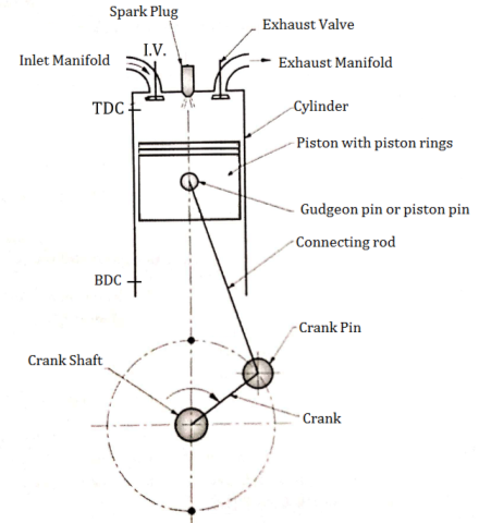
- Fig. below shows important components of 4 stroke petrol engine (S.I.)
|
Fig: Construction of four stroke S. I. engine
An Engine consists of following important Components.
- Cylinder
- Crank and crankshaft
- Spark plug
- Crank pin&Gudgeon pin
- Cylinder head
- Suction and exhaust manifold
- Piston
- Connecting rod
- Inlet and exhaust valve
- Piston rings
- Cylinder: It is the main body of an I.C. engine in which piston reciprocates to develop power. It has to withstand very high pressures and temperatures, because the combustion takes place in the cylinder. It may be air cooled or water cooled. It is generally made of cast iron or alloy steel.
- Piston: it is used to compress the charge (air fuel mixture) during compression stroke and to transmit the force to connecting rod and then crank during power stroke.
- Crankand crankshaft: Crank is the integral part of the crankshaft and crankshaft is the backbone of the engine. Crankshaft is supported in main bearings.
- Connecting rod: Its small end is connected to the piston and big end is connected crank. It converts reciprocating motion of piston into rotary motion of crankshaft.
- Inlet and exhaust valve: Inlet valve controls the admission of the charge during Suction stroke and exhaust valve is used for removal of exhaust gases after doing work on the piston.
- Spark plug: It is used to initiate the spark for combustion of air-fuel mixture in petrol engines.
- Crank pin and Gudgeon pin: Crank pin is used to connect big end of connecting rod to the crank and gudgeon pin is used to connect small end of connecting rod to the piston.
- Cylinder head: it is used for closing the one end of the Cylinder. It houses inlet and exhaust valves through which charge is taken inside the cylinder and burned gases are exhausted to atmosphere from the cylinder.
- Piston rings: These are housed in the circumferential grooves provided on the surface of piston. It gives tight fit between piston and cylinder and prevents leakage of high pressure gases.
- Suction and exhaust manifold: Suction manifold is the passage which carries the charge carburetor to the engine whereas exhaust manifold is the passage which carries the exhaust gases from the exhaust valve to the atmosphere.
Working of four stroke S. I. Engine (Four Stroke Petrol Engine)
There are four strokes in the working of S. I. Engine which are as follows:
- Suction stroke
- Compression stroke
- Expansion or working or power stroke
- Exhaust stroke
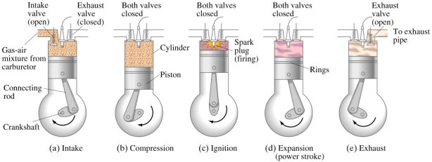
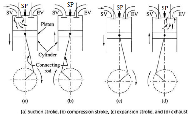
- SUCTION STROKE OR INTAKE STROKE:
- The suction stroke starts with the piston at top dead centre position (TDC). During this stroke, the piston moves downwards by means of crank shaft.
- The inlet valve is opened, and the exhaust valve remains closed. The partial vacuum is created by the downward movement of the piston. Due to this the fresh charge (mixture of air and petrol) from the carburetor is taken into cylinder through the inlet value.
- The stroke is completed during the half revolution (180°) of the crank shaft, whichmeans at the end of the suction stroke, piston reaches the bottom head centre position
|
|
Fig: Working of four stroke S. I. engine
- COMPRESSION STROKE:
- During this stroke the inlet and exhaust valves remain closed and the piston returns from bottom dead centre position (BDC) to TDC.
- As the piston moves up, the charge is compressed upto clearance volume. During compression the pressure and temperature rises.
- Just before the completion of the compression stroke, the charge is ignited by means of an electric spark, produced at the spark plug. Due to instantaneous burning of charge, pressure and temperature of charge tremendously rises.
- WORKING OR EXPANSION STROKE OR POWER STROKE:
- During this stroke the inlet and exhaust valves remain closed. The expansion of gases due to the heat of combustion exerts pressure on the piston due to which the piston moves downward, doing some useful work.
- High pressure and temperature of gases pushes the piston in downward direction. Piston moves from TDC to BDC.
- EXHAUST STROKE:
- During this stroke the inlet valve remains closed and exhaust valve is opened. The piston moves upward (from BDC to TDC position) with the help of energy stored in the flywheel during the working stroke.
- During upward movement, piston pushes out burnt gases through the exhaust value. At the end of exhaust stroke, piston reaches to TDC position, exhaust valve is closed and inlet valve is opened which starts the next cycle.
2.1.27 FOUR STROKE C. I. ENGINE (FOUR STROKE DIESEL ENGINE)
- C.I. stands for Compression ignition. Generally all Diesel engines are Compression Ignition engines (C. I.)
- Construction of four stroke S.I. (Petrol) & four stroke C. I. (Diesel) engine is much similar. Only difference is that SPARK PLUG of S.I. engine is replaced by Fuel Injector (F.I.) in C.I. Engines.
- Unlike S.I. engines, In C.I. or diesel Engines only air is taken into the cylinder during the suction or inlet stroke and diesel fuel is injected into compressed air at the end of compression stroke
Construction of four stroke C. I. Engine (Four Stroke Diesel Engine)
- Fig. below shows important components of 4 stroke Diesel engine (C.I.)
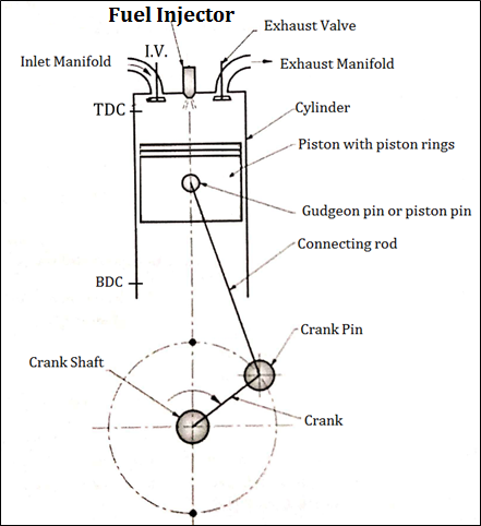
Fig: Construction of four stroke C. I. engine
An Engine consists of following important Components.
- Cylinder
- Crank and crankshaft
- F.I. (Fuel Injector)
- Crank pin&Gudgeon pin
- Cylinder head
- Suction and exhaust manifold
- Piston
- Connecting rod
- Inlet and exhaust valve
- Piston rings
- Fuel Injector: It is used to inject the fuel into the cylinder of engine at the end of compression stroke.
- Remaining parts of four stroke C.I. or diesel engine has same function like four stroke S.I. engine.
Working of four stroke C. I. Engine (Four Stroke Diesel Engine)
There are four strokes in the working of C. I. Engine which are as follows:
- Suction stroke
- Compression stroke
- Expansion or working or power stroke
- Exhaust stroke
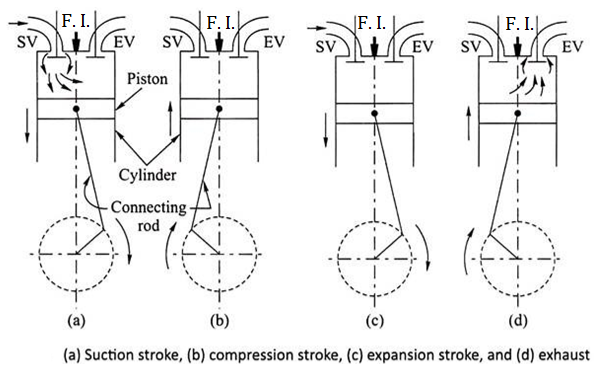
- SUCTION STROKE OR INTAKE STROKE:
- The suction stroke starts with the piston at top dead centre position (TDC). During this stroke, the piston moves downwards by means of crank shaft.
- The inlet valve is opened, and the exhaust valve remains closed. The partial vacuum is created by the downward movement of the piston. Due to this the fresh air is taken into cylinder through the inlet value.
- The stroke is completed during the half revolution (180°) of the crank shaft, whichmeans at the end of the suction stroke, piston reaches the bottom head centre position
|
Fig: Working of four stroke C. I. engine
- COMPRESSION STROKE:
- During this stroke the inlet and exhaust valves remain closed and the piston returns from bottom dead centre position (BDC) to TDC.
- As the piston moves up, the AIR is compressed upto clearance volume. During compression the pressure and temperature of air rises.
- Just before the completion of the compression stroke, the Diesel Fuel is injected into this compressed air by using fuel injector. Due to very high pressure and temperature of air, Diesel fuel starts burning instantaneously producing very pressure and temperature of gases.
- WORKING OR EXPANSION STROKE OR POWER STROKE:
- During this stroke the inlet and exhaust valves remain closed. The expansion of gases due to the heat of combustion exerts pressure on the piston due to which the piston moves downward, doing some useful work.
- High pressure and temperature of gases pushes the piston in downward direction. Piston moves from TDC to BDC.
- EXHAUST STROKE:
- During this stroke the inlet valve remains closed and exhaust valve is opened. The piston moves upward (from BDC to TDC position) with the help of energy stored in the flywheel during the working stroke.
- During upward movement, piston pushes out burnt gases through the exhaust value. At the end of exhaust stroke, piston reaches to TDC position, exhaust valve is closed and inlet valve is opened which starts the next cycle.
2.1.28 TWO STROKE S. I. ENGINE (TWO STROKE PETROL ENGINE)
- Two stroke engine is a type of internal combustion engine which completes a power cycle with two strokes (up and down movements) of the piston during only one crankshaft revolution.
Construction of Two stroke S. I. Engine (two stroke petrol engine)
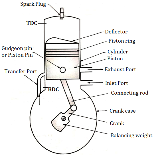
- Fig. below shows important components of 2 stroke petrol engine (S.I.)
Two Stroke Engine consists of following important Components.
- Cylinder
- Crank and crankshaft
- Spark plug
- Crank pin&Gudgeon pin
- Cylinder head
- Inlet and exhaust port
- Piston
- Connecting rod
- Transfer port
- Piston rings
|
Fig: Construction of two stroke S. I. engine
- Piston: It is used to compress the charge (air fuel mixture) during compression stroke and to transmit the force to connecting rod and then crank during power stroke. Piston of two stroke engine is given a specific crown shape (deflector) which guides the charge in the upward direction.
- Inlet and exhaust Port: Inlet Port controls the admission of the charge into the crank case and exhaust port is used for removal of exhaust gases after doing work on the piston.
- Transfer Port:The charge present into crank case is transferred into cylinder of engine by using transfer port.
- In two stroke engine valves are therefore eliminated and ports are used for suction and exhaust purpose.
- Remaining parts of two stroke engine have same function like four stroke engine.
Working of Two stroke S. I. Engine (two stroke petrol engine)
- FIRST STROKE:
- Consider that, initially the piston is at BDC. The arrangement of the ports is such that the piston performs two operations simultaneously.
- When the piston starts rising from BDC, it Closes the transfer port and exhaust port and the already existing charge in the cylinder is compressed.
- At that time, due to upward motion of piston, vacuum is created in the crankcase. As soon as the inlet port is uncovered the fresh charge (air + fuel) is sucked in the crankcase and the charging is continued until the crankcase is filled.
- At the end of this first stroke piston reaches TDC. Just Before the completion of this compression stroke, thecompressed charge is ignited using spark plug.
- SECOND STROKE:
- In this stroke, piston moves from TDC to BDC.Due to combustion of charge, very high pressure and temperature gases are created.
- These high pressure gases is exerts large amount of force on the crown of the piston and thus piston is pushed down which produces some useful work.
- The downward movement of piston closes the inlet port and compresses the charge already sucked in the crankcase. This fresh charge is transferred on the top side of the piston through transfer port.
- At that time, exhaust port opens and burnt gases are escaped.
2.1.29 TWO STROKE C. I. ENGINE (TWO STROKE DIESEL ENGINE)
- Two stroke engine is a type of internal combustion engine which completes a power cycle with two strokes (up and down movements) of the piston during only one crankshaft revolution.
- Construction of two stroke S.I. (Petrol) &two stroke C. I. (Diesel) engine is much similar. Only difference is that SPARK PLUG of S.I. engine is replaced by Fuel Injector (F.I.) in C.I. Engines.
- Unlike S.I. engines, In C.I. or diesel Engines only air is taken into the cylinder during the suction or inlet stroke and diesel fuel is injected into compressed air at the end of compression stroke.
Construction of Two Stroke C. I. Engine (Two Stroke Diesel Engine)
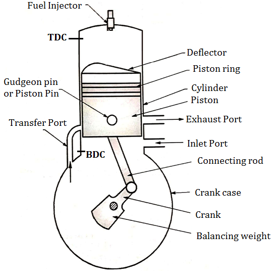
- Fig. below shows important components of 2 stroke diesel engine (C.I.)
Two Stroke Engine consists of following important Components.
- Cylinder
- Crank and crankshaft
- Fuel Injector (F. I.)
- Crank pin&Gudgeon pin
- Cylinder head
- Inlet and exhaust port
- Piston
- Connecting rod
- Transfer port
- Piston rings
|
Fig: Construction of two stroke C. I. engine
- Piston: It is used to compress the charge (air fuel mixture) during compression stroke and to transmit the force to connecting rod and then crank during power stroke. Piston of two stroke engine is given a specific crown shape (deflector) which guides the charge in the upward direction.
- Inlet and exhaust Port: Inlet Port controls the admission of the charge into the crank case and exhaust port is used for removal of exhaust gases after doing work on the piston.
- Transfer Port:The charge present into crank case is transferred into cylinder of engine by using transfer port.
- In two stroke engine valves are therefore eliminated and ports are used for suction and exhaust purpose.
- Remaining parts of two stroke engine have same function like four stroke engine.
Working of Two Stroke C. I. Engine (Two Stroke Diesel Engine)
- FIRST STROKE:
- Consider that, initially the piston is at BDC. The arrangement of the ports is such that the piston performs two operations simultaneously.
- When the piston starts rising from BDC, it Closes the transfer port and exhaust port and the already existing AIR in the cylinder is compressed.
- At that time, due to upward motion of piston, vacuum is created in the crankcase. As soon as the inlet port is uncovered the fresh AIR is sucked in the crankcase and the charging is continued until the crankcase is filled.
- At the end of this first stroke piston reaches TDC. Just Before the completion of this compression stroke, Diesel Fuel is sprayed into thecompressed air. Due to very high pressure and temperature of the air, diesel fuel starts burning instantaneously.
- SECOND STROKE:
- In this stroke, piston moves from TDC to BDC.Due to combustion of diesel, very high pressure and temperature gases are created.
- These high pressure gases is exerts large amount of force on the crown of the piston and thus piston is pushed down which produces some useful work.
- The downward movement of piston closes the inlet port and compresses the AIR already sucked in the crankcase. This fresh AIR is transferred on the top side of the piston through transfer port.
- At that time, exhaust port opens and burnt gases are escaped.
2.1.30 DIFFERENCE BETWEEN FOUR STROKE AND TWO STROKE ENGINE
4 STROKE ENGINE | 2 STROKE ENGINE |
Four stroke engine completes 2 rotations of crankshaft after completing one cycle. | Two stroke engine completes 1 rotation of crankshaft after completing one cycle. |
Power is produced once every 4 strokes of the piston. | Power is produced once during 2 strokes of the piston. |
Less power produced for same size of engine | More power produced for same size of engine |
Engine design is a bit complicated due to valve mechanism which is operated through gear & chain mechanism. | Two stroke engine has ports which makes it's design simpler. |
No need of adding oil or lubricant to fuel. | Addition of oil is required. |
Top side of the piston is flat. | A bump or protuberance may be needed on top side of piston. |
Higher Volumetric Efficiency | Lower Volumetric Efficiency |
Four stroke engines are heavier. | Two stroke engines are lighter comparatively. |
Higher Thermal Efficiency | Lower Thermal Efficiency |
2.1.31 DIFFERENCE BETWEEN S.I. (PETROL) AND C. I. (DIESEL) ENGINE
S.I. (Petrol) ENGINE | C. I. (Diesel) ENGINE |
Works on Otto Cycle | Works on Diesel Cycle |
Petrol is used as Fuel | Diesel is used as Fuel |
Carburettor is required in petrol engines. | No Carburettor is required. Instead of that Fuel Injector is required in diesel engines. |
Low Compression ratio. ( 5 to 10) | High Compression ratio. ( 14 to 20) |
Spark is used to ignite the fuel. | Fuel is self-ignited due to very high temperature obtained by compression of air. |
Low thermal Efficiency because of low compression ratio. | High thermal Efficiency because of High compression ratio. |
Light Weight due to lower compression ratio and pressure produced. | Heavy due to higher compression ratio and pressure produced. |
Easy to start due to spark plug | Difficult to start due to high compression ratio |
Less Costly | Expensive |
More running cost due to higher petrol price | Less running cost due to lower diesel price |
Reference Books
1. Khan, B. H., “Non Conventional Energy Sources, Tata McGraw-Hill Publisher Co. Ltd.
2. Boyle, Godfrey, “Renewable Energy”,2nd Ed., Oxford University Press
3. Khurmi, R.S. ,and Gupta, J. K.,“A Textbook of Thermal Engineering”, S. Chand & Sons
4. Incropera, F. P. and Dewitt, D.P., (2007), “Fundamentals of Heat and Mass Transfer, 6th Ed., John Wiley and Sons, USA
5. Groover,Mikell P., (1996), “Fundamentals of Modern Manufacturing: Materials, Processes, and Systems”, Prentice Hall, USA
6. Norton, Robert L., (2009), “Kinematics and Dynamics of Machinery”, Tata McGrawHill
7. Cleghorn, W. L., (2005), “Mechanisms of Machines”, Oxford University Press
8. Juvinal, R. C., (1994), “Fundamentals of Machine Component Design”, John Wiley and Sons, USA
9. Ganeshan, V., (2018), “Internal Combustion Engines”, McGraw Hill
10. Anderson, Curtis Darrel and Anderson,Judy, (2010), “Electric and Hybrid Cars: A History”, 2nd Ed., McFarland
