UNIT 5
Introduction to Manufacturing
- Manufacturing is the process of converting the raw material into finished product using machines.
- The word manufacturing means the making of goods and articles by hand and/or by machinery.
- In this Unit we will study various processes required to produce parts and to assemble them into machines and mechanisms.
|
Manufacturing processes | Working Principle | Examples | |
1 | Primary Shaping Process: Casting Processes |
| Sand casting,Permanent casting, Centrifugal Casting, die casting etc. |
2 | Metal Forming OR Mechanical Working |
|
|
3 | Sheet Metal Working |
|
Blanking, Piercing, Punching, Perforating, Slitting, Lancing, Notching, Shearing etc
Drawing & Deep Drawing, Forming, Coining, Embossing, Bending etc. |
4 | Machining or Metal Cutting |
|
|
5 | Metal Joining Process |
|
|
6 | Surface Finishing Process |
|
|
5.1.1 Basic Terminology in Casting Process
|
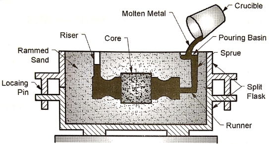
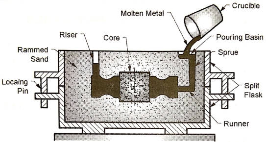
Fig: Casting Process
- Mould: Cavity (Hallow space) of the shape which is to be manufactured. The process of making the mould is called mould making.
- Pattern: It is model or replica of the object to be cast.
- Core: Internal hole spaces which are not to be filled by molten metal – core.
- Cope: Upper part of casting flask is called as Cope box.
- Drag: Lowerpart of casting flask is called as Drag box.
- Crucible or Ladle: Are used to carry molten metal from the furnace to the moulding box.
- Pouring basin: Molten metal is initially poured into pouring basin.
- Sprue: It is a channel through which the molten metal is brought to the runner.
- Runner: Molten metal is carried from the sprue base to the mould cavity.
- Riser: It is a passage made in cope to permit the flow of excess molten metal. Escape of air and gases.
- Gate: A Gate is a Channel which connects the Runner with Mould Cavity.
5.1.2 Different steps in sand casting process
- Step 1: Patten making:
- Pattern is defined as model or replica of a casting, used for making a cavity or mould.A cavity of Desired Shape).
- Wood is most commonly used material for patterns because it is easy to shape into any complex shape. Sometimes Metals (like Cast Iron, Al, Cu, and Bronze). Plastics, Plaster of Paris are also used for Patterns.
|
Fig:Pattern
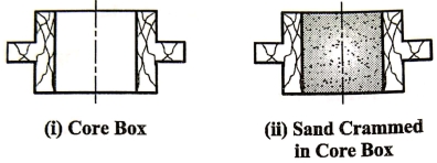
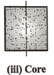
- Step 2: Core making
- Core is predetermined shape made from the sand and placed in the mould in mould for provision of hole or hallow space.
|
|
Fig:Core making
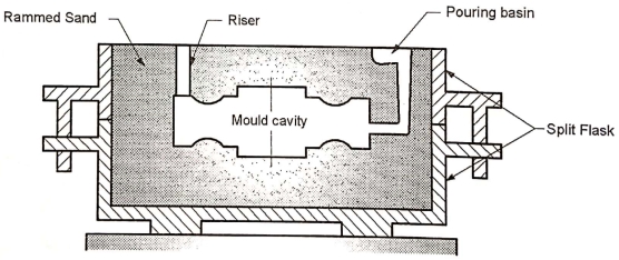
- Step 3: Mould Making
- Mould making is the process of making a cavity which conforms to the shape of the desired component, in the sand.
- A Gating System (molten metal flow channel) consisting of Pouring Basin, Sprue, Runner, Gate and Riser is prepared along with mould cavity.
- Mould Box (Flask) are generally made from wood and they are used in combination of two halves; Upper Half is called as Cope and Lower Half is called as Drag.
|
Fig:MouldMaking
- Step 4: Melting and pouring of molten metal
- Metal is melted in furnace and poured into a mould cavity.
- Molten Metal Flow Sequence is: Furnace → Ladle → Pouring Basin → Sprue → Runner → Gate → Mould Cavity → →Riser
|
Fig: Melting and pouring of molten metal
- Step 5: Cooling and solidification
- Molten metal is allowed to cool and solidify in the mould.
- Step 6: Cleaning and Inspection:
- After solidification, the sand mould is broken to take out the casting from the mould cavity. The casting is the cleaned and inspected.
5.1.3 Advantages of casting process
- Highly Economical, Does not require highly skilled persons.
- Suitable for Complex shapes, almost all metals, alloys, some plastics can be casted.
- Suitable for small, medium and large scale production.
- Castings have better vibration damping properties.
5.1.4 Limitations of casting process
- Castings require more machining and finishing operations.
- Castings are generally weak in tension, Welding of cast components is difficult.
- Air pollution, requires more space and energy, manpower.
- Poor Surface Finish, Poor Dimensional Accuracy.
- Process not suitable for precision parts (high dimensional accuracy) & with thin sections.
- Each time mould has to be broken to take out the casting part. So each casting requires a new mould.
5.1.5 Applications of casting process
- Automobile: Piston, Piston Rings, Cylinder Head, Cylinder Block, Clutch Housing, Gear-Box Housing, Gear Blanks.
- Air craft: Jet Engine Blades, Gear-Box Housing, Gear Blanks
- Machine Tools: Machine-Tool Beds, Columns, Frames, Pulleys, Flywheel, Gears
- Gear box housing and motor housing, Pump Parts
- Sanitary Fittings, Water Supply Pipes, Valve Bodies, Turbine blade and housing
- Road rollers.
- Metal Forming is a process in which the component of desired size and shape is producedthrough(controlled) plastic deformation of metalunder the action of external force (tensile, compressive or combination of them).
- Metal forming processes can be carried out on metal in hot or cold conditions.
Various metal forming processes are
Extrusion: | Production of Metal Bars / Rods |
Rolling: | Production of Metal Sheets |
Wire Drawing: | Production of Metal Wires |
Forging (Hot and Cold): | Production of Machine Parts Example: Axle, Spindle, Rocker, Lever, Connecting Rod, Crank-Shaft |
5.1.6 Forging
- Metal Forgings a process in which the component of desired size and shape is produced through (controlled) plastic deformation of metal under the action of external force using hand hammer, power hammer or a press.Forging processes can be carried out in both cold condition.
- The machine on which forging is carried out is called as forging press.
- The forging press can be: (i) mechanical press or (ii) hydraulic press.
Principle of Hand Forging Process
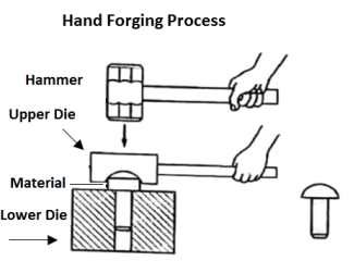
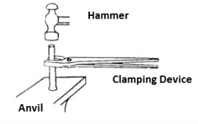
- It is the process of deforming the hot material/work piece into the required shape by applying the repeated blows of hammer held in hand. The hot material is held in one hand by using suitable clamping device and kept on anvil block whereas, hammer blows are given by hammer held in another hand.
|
- In this process force is applied manually by using hand hammer.The Billet or material is kept between the lower and upper die. Due to application of force by hammer the material spreads inside the cavity and takes the shape of the cavity.Sometimes the Dies used are flat. Final shape is given to the material by using hammer only.
Working Principle of Forging Process (using Mechanical Press)
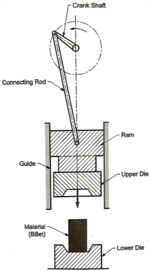
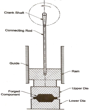
- A diagram below shows the mechanical press. In mechanical press, the ram is driven by an electric motor through the crank shaft and the connecting rod.
- As electric motor rotates the crankshaft, crankshaft and connecting rod together converts rotary motion into reciprocating motion of the Ram. For first half revolution of crank, ram moves downward while for next half revolution, ram moves upward.
- The forging press machinealso consists of a lower die fixedto frame while upper die is connected to the ram. The hot material is kept on the lower die.
- During the downward stroke of the ram, the upper die exerts the sudden compressive force on the hot material. Due to sudden compressive force, the hot material is converted into the desired shape.
|
a) Before forging b) after forging |
Figure: Forging process using Mechanical Press
Working Principle of Forging Process (using Hydraulic Press)
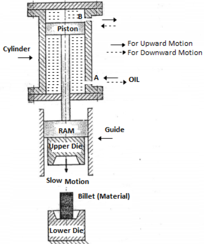
- A diagram below shows the hydraulic press. In hydraulic press, the ram is driven by hydraulic cylinder.
- For Lifting the upper die, the hydraulic fluid is supplied to the lower part of the cylinder through the port A.
- For moving the upper die downward, the supply of the hydraulic fluid to the port A is cut off. The hydraulic fluid is now supplied to upper part of the cylinder through the port B.
- The downward motion of the piston is resisted by the hydraulic fluid present in the lower part of the cylinder. Therefore, the downward motion of the die is slow and gradual.
- When Piston is moving downward, it exert the compressive force on the billet slowly and gradually.
|
Figure: Forging process using Hydraulic Press
- The forging press machinealso consists of a lower die fixedto frame while upper die is connected to the ram. The hot material is kept on the lower die.
- During the downward stroke of the ram, the upper die exerts the compressive force on the hot material.
- Due to sudden compressive force, the hot material is converted into the desired shape or The Material is compressed in the cavity between upper and lower die.
Materials Used for Forging Process
- Properties of materials used for forging process: The material used for forging process must be a ductile material. Ductility is the ability of the material to sustain substantial plastic deformation without fracture.
- Materials used for forging: low and medium carbon steels, alloy steels, stainless steels, copper alloys, aluminium alloys etc.
- Hard and Brittle Materials like Cast Iron, High Carbon Steel cannot be forged.
Advantages of Forging
- Stronger / Tougher than Cast/ Machined parts of same material.
- Better mechanical properties, strength and toughness.
- Better resistance to shock and vibrations, Can be welded.
- Better Surface finish, High Dimensional accuracy and control.
Limitations of Forging
- Brittle materials like Cast Iron, High Carbon Steel cannot be forged.
- Complex shapes cannot be forged.
- Very large size parts cannot be forged.
- Dies are very costly
- More noise and vibration, noise pollution during the forging operation.
Applications of Forging
- Forging parts are stronger and tougher than cast or machined parts of same material. They are capable to withstand (resist) Impact Loads, Shock Loads, Fatigue Loads and vibrations.
- Very Strong or generally moving parts of the machine which are subjected to variable loading are produced by forging process.
- Connecting Rod, Crank-Shaft, Propeller Shaft
- Axles, Levers, Gear Blanks, Rocker arms
- Crane Hook, Bolts, Nuts, Washers, Collars
- Turbine Blades, Dies, Spanners, Hand Tool
- Knife Blades, War Equipment like Sword, Arrows, Protective Armour, Helmets
Classification of Forging Process
- According to Type of Dies used
- Open Die Forging
- Closed Die Forging
- According to Working Temperature
- HOT Forging (Hot working)
- COLD Forging (Cold working)
1) Open Die Forging Process
|
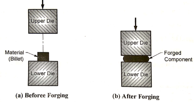
- The Dies used in this process are flat or having a very simple shape.
- In this process the Billet or material is kept between the lower and upper die. Due to application of force by hammer or by forging press machine the material spreads between two dies.
2) Closed Die Forging Process
|
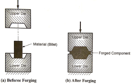
- In closed die forging process, the material or workpiece is deformed between the two dies which have the impressions of the desired shape as shown in above figure.
- When the two dies are closed, the cavity formed is of the desired final shape.
3) HOT & COLD Forging
HOT Forging (Hot Working)
- Mechanical working of metals above its re-crystallization temp but below melting point is known as HOT Working or HOT Forging.The average temperature necessary for hot forging of steel components is 1100°C to 1200°C.
Advantages
- The hot forging process requires less force and energy.
- The hot forging increases the ductility of material.
- The hot forging process requires less powerful machines compared to cold forging.
Disadvantages
- The thermal contraction of the workpiece takes place during the cooling. Therefore, this process cannot produce the components with high dimensional accuracy.
- In hot forging, the reaction between the metal and the surrounding atmosphere leads to oxidation and formation of scales on the surface.
COLD Forging (Cold Working)
- Mechanical working of metals below its re-crystallization temp is known as COLD Working or COLD Forging.
- The deformation of material or work piece into predetermined shape is carried out at a temperature below its recrystallization temperature. (Usually room temperature).
- Normally the cold forging process is carried out at room temperature.The cold forging is generally preferred when the material is soft, like aluminium.
Advantages
- The cold forging gives high dimensional accuracy of the component.
- In cold forging process, there is no reaction between the metal and the surrounding atmosphere, hence there is no formation of scales on the surface.
Disadvantages
- The cold forging process requires high energy and high die forces.
- The cold forging process requires heavier and more powerful machines.
Hot Forging (Hot Working) | Cold Forging (Cold Working) |
Above Recrystallization Temp | Below Recrystallization Temp |
Carried out High Temperature | Carried out at Room Temp |
Chances of Oxidation | No Chances of Oxidation |
Poor Dimensional Accuracy Forged Component contract after cooling | High Dimensional Accuracy |
Needs less Force and Power | Needs large Force and power |
Low power machine needed | High Power machine needed |
Residual Stresses absent | Residual Stresses Present |
No Strain Hardening | Strain Hardening present |
Grain Structure is refined during the process | Grain Structure is disturbed (distorted) during the process |
Grain Structure is refined which results in Improved Mechanical Properties like strength, toughness, % Elongation. | Strain Hardening (Work Hardening) improves Yield Strength & Ultimate Strength. |
Example : Hot Rolling Process, Hot Forging Process, Connecting Rod, Crankshaft | Example : Wire drawing, Drawing, Forming |
5.1.7 Extrusion
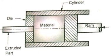
|
Figure: Extrusion Process
- Extrusion is a metal forming process used for manufacturing the long and straight parts of fixed cross-section.
- In extrusion process, material (metals or plastics) in the form of billets is kept inside the cylinder and forced to flow through the die of desired cross-section using ram.
- As a result, a part or component of desired cross-section is produced, as shown in Fig.
- In extrusion process, ram is driven by an electric motor or by hydraulic cylinder.
Materials used for Extrusion Process:
- Steel, aluminium alloy, magnesium, thermoplastic etc.
Advantages of Extrusion Process
- Components produces by extrusion process have high accuracy and good surface finish.
- Cost of components produced by extrusion process is low.
- Extrusion process can produce a components of large length.
- High rate of production.
- Metal as well as plastic parts can be produced by extrusion process.
Limitations of Extrusion Process
- High initial cost of set-up.
- Extrusion cannot produce components of varying cross-section.
Applications of Extrusion Process
- The extrusion process can be used for producing collapsible tubes, Aluminium cans and cylinders, bars, tubes, gear blanks etc.
5.1.8 Wire Drawing
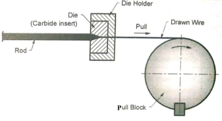
- Wire drawing is the cold working process of producing the wire from the rod through the successive reduction of diameter.
- In wire drawing process, the metal is pulled through a die. A tensile force is applied to the metal on the exit side of the die for pulling purpose.
- There is a gradual reduction of cross-sectional area inside the die. Due to this, as the tensile force is applied to the metal on the exit side of the die, the die exerts the radial compressive force on the metal.
- This causes the plastic flow of the metal. For obtaining the significant changes in size, the multiple passes are required.
|
- The -wire drawing process gives excellent dimensional accuracy and surface finish. For wire drawing process, the material must have a good ductility.
- The drawing speed of the wire drawing process ranges from 1 m/s to 50 m/s.
- It is process of manufacturing component or parts from metal sheets (having thickness from 0.1 mm to 6 or 8 mm)
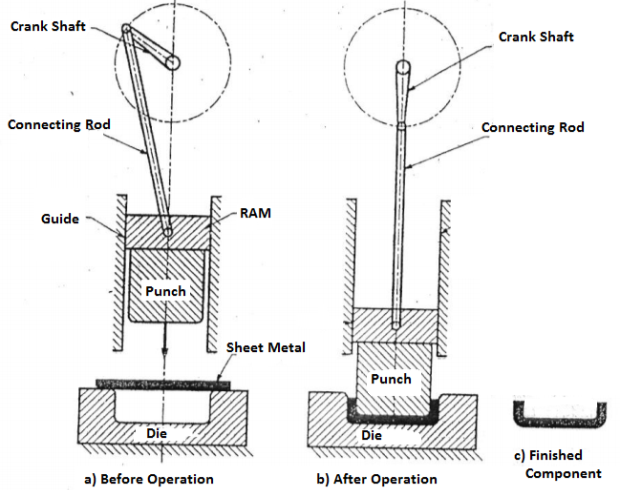
- During the operation Metal sheet is kept on the die (which is stationary) and punch (which
is moving) moves downwards. The punch forces metal sheet into die cavity. - The sheet-metal working is generally carried out with the machine tool called as press. Therefore, it is also known as press working.
- Fig. shows a schematic diagram of a press used for sheet-metal working. The tool used on the press for carrying out the sheet-metal working are called die and Punch.
- Die is a stationary part having cavity which conforms to the shape of the desired component. It is fixed to the bed of the press machine.
- Punch is a part which enters in the die cavity to-carryout the operation. The punch is attached to the ram, which is free to reciprocate in a guide.
- The ram is driven by the crankshaft through the connecting rod. The piece of metal sheet which is to be given a shape is kept over the die as shown in Fig.
|
- The force is applied through the punch. Small clearance is kept between the punch and die for the thickness of metal-sheet.
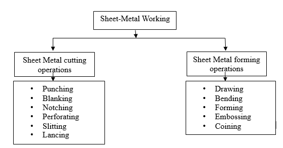
5.1.9 Types of Sheet Metal Working Process
|
1) Sheet Metal Cutting/Shearing process
- In this process
- The material is stressed beyond the ultimate strength.
- The metal-sheet is cut using punch and die;
- The desired part of the metal sheet is used; and
- The remaining part of the metal-sheet is discarded.
- The sheet metal cutting processes are also known as shearing operations because the metal cutting is due to shearing of metal across the cutting edges, in these processes.
- Some of the metal cutting processes are as follows:Blanking, Piercing, Punching, Perforating, Slitting, Lancing, Notching, Shearing or Cutting
2) Sheet Metal Forming Process
- In this process the flat plate of a metal sheet is converted into a desired shape without wasting the material.
- There is no material cutting involved in this process.
- Some of the metal forming processes are as follows: Drawing and Deep Drawing, Forming, Coining (Squeezing), Embossing, Bending [V, U, Edge, Angle, Curling]
5.1.10 Sheet Metal Cutting/Shearing process
1) Blanking
|
|
|
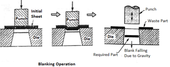
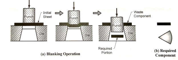
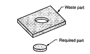
- Blanking is the operation of cutting out a piece of the required shape from a metal sheet using a punch and a die.
- In this operation outside area of sheet metal is scrap. The part which is cut from a sheet metal is called as blank. This is the required part in the blanking operation.
2) Punching& Piercing
|
|
|
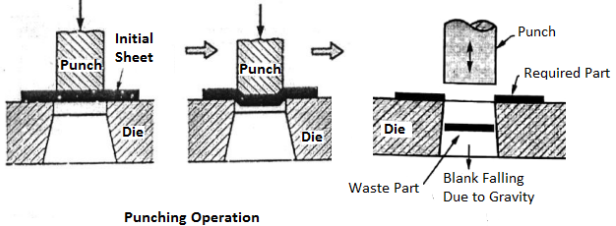
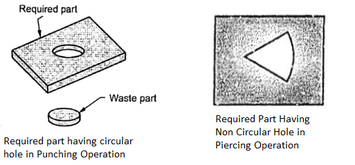
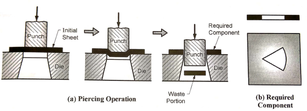
- Punching is the operation of producing a circular hole in a metal sheet by using a punch and a die.
- In this operation, the metal sheet with the hole is the required component while the
material punched out to make the hole is the waste portion. - In punching a circular hole is produced whereas in piercing the hole of any shape
is produced.
3) Perforating
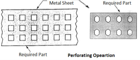
- Perforating is the operation of producing a number of evenly spaced holes in a metal sheet by using a punch and a die.
|
4) Slitting
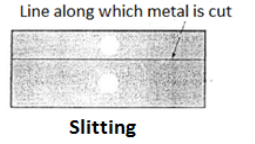
- Slitting is the operation of cutting a metal sheet in a straight line along the length
| |
| |
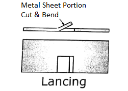
5) Lancing
- It the operation of cutting a part of metal sheet through some portion of its length and then bending the cut portion.
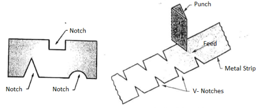
6) Notching
- It the operation of cutting a part of metal sheet through someportion of its length and thenbending the cut portion.
|
5.1.11 Sheet Metal Cutting/Shearing process
1) Drawing & Deep Drawing
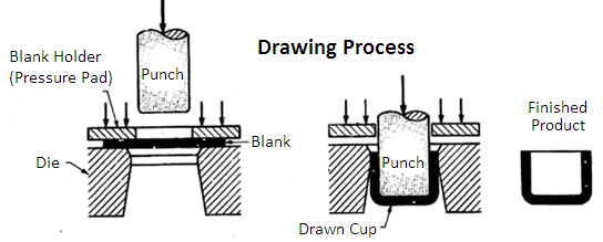
- Drawing is a process of forming a flat metal sheet into a three dimensional hollow shape by means of a punch that causes the metal to flow into the die cavity. (By plastic flow of metal sheet into the clearance between punch and die).
- Drawing process is called Deep drawing when Length (or depth) of formed cup is greater than its Dia.
|
- In a drawing process, shown in Figure, a punch forces the blank (metal sheet) into a die cavity so that it takes a desired cup shape.
- During a drawing process, the blank diameter decreases, and hence considerable compressive stresses are induced in the outer portion (flange) of the blank. If the compressive stress becomes excessive, the outer portion (flange) of the blank may wrinkle. To avoid the possibility of wrinkling, a blank holder or pressure pad is provided.
- Examples of components produced by drawing process: Seamless drums, cans, cups, electrical and automobile components, etc.
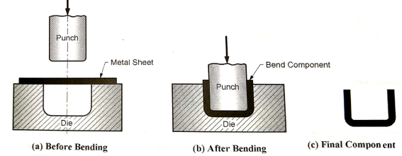
2) Bending
|
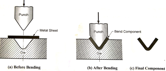
- Bending is a metal forming process by which a straight length metal sheet is transformed into a curved length. Fig. below shows the bending process.
- In bending operation, the metal sheet is stressed beyond its elastic limit but below its ultimate strength. Therefore there is a plastic deformation and the metal sheet retains the bend shape even after the force applied by punch is removed.
- However, there can be some amount of elastic recovery of the metal sheet after the force is removed. This causes an increase in the bend angle. This phenomenon is known as spring back.
- To compensate for spring back, the punch and mating dies are made with included angles slightly less than required by the final component. During bending operation, the component is bent to an angle greater than desired and it finally spring back to the desired angle.
- Examples: Angles and channels.
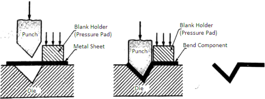
V-Bending
- The V-bending process is shown in above Fig. In this, a wedge shaped punch forces the metalsheet into a wedge shaped die. The bend angle may be acute, 90°, or obtuse.
U Bend
|
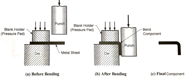
Edge Bending
|
- In edge bending process, as shown in Fig., the metal sheet is held, like acantilever beam, on a die with the help of a blank holder: The flat punch forces theoverhanging portion of the metal sheet against the vertical face of the die.
Angle Bending
- In angle bending process, as shown in Fig., the metal sheet is bent to the sharp angle.
|
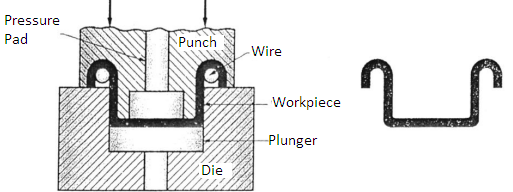
Curling
|
- In curling process, an edge of a circular cross-section is formed along a sheet or at the end of a tube. The curling process is used in the manufacturing of vessels, pans, pots, etc.
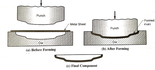
3) Forming
- In this process, Sheet metal plastically deforms to take the shape of cavity formed between punch and die.Forming is a process of shaping a flat metal sheet into a surface of desired profile.
|
|
- In forming process, the shape of punch and die surface is directly reproduced.
- Example: Auto & Aircraft body panels, Steel Furniture, toys.
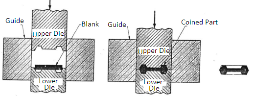
4) Coining
- Coining is the process of cold squeezing of metal in which all the surfaces are confined within a set of dies.
|
- In a coining process, the metal blank of proper size is placed on the lower set and large pressure is applied on the blank by upper die. The pressure required is about 4-6 times the strength of the metal blank.
- Under the sever pressure, the metal flows in the cold state and fills up the cavity of the die set. The final component gets a shape impressions on its surfaces, corresponding to the engravings on the surfaces of dies.
- Examples: coin, medals, badges, etc.
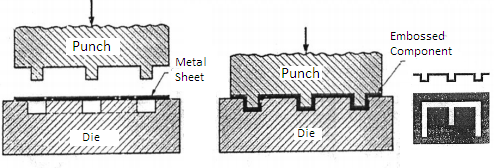
5) Embossing
- Embossing is the process of producing the depressed or raised impression of letters, figures or designs on metal sheet. In embossing process shown in Fig., the punch and die are having the projections and depressions respectively of the desired shape.
|
- The metal sheet is placed on the die and the force is applied on it by the punch. The final component will have depressed details on one side and raised details on the other side.
- Embossing process does not require as high pressure as required by coining process.
- Examples: Name plates,identification tags, and aesthetic designs on metal sheets or foils.
5.1.12 Welding
- Welding is a process of joining two or more parts together at their contacting surfaces by application of heat and/or filler material with/without pressure.
- Welding is the process of joining the two metallic parts together by heating them to a plastic or semi-molten state, with or without the application of a pressure and with or without a filler material.
- The welding process needs three input elements
- (i) Heat: In welding process, the heat required for fusing the two parts is obtained from: electric energy (electric arc) or combustion of gases or chemical reaction. Heat is essential input element in welding process.
- (ii) Application of pressure: The application of pressure is an optional input element in welding process. In some welding processes, the two parts to be welded are forced together by external pressure.
- (iii) Filler material: The filter material is again an optional input element is welding process. In some welding processes, the filler material is supplied by welding rod.
5.1.13 Classification of Welding Processes
- Arc Welding: Carbon arc Welding, Metal arc Welding, Metal inert gas Welding, Tungsten inert gas Welding, Plasma arc Welding, Submerged arc Welding, Electric Arc Welding
- Gas Welding:Oxy-acetylene Welding, Air-acetylene Welding, Oxy-hydrogen Welding
- Resistance Welding: Butt Welding, Spot Welding, Seam Welding
5.1.14 Electric Arc Welding(SMAW - shielded metal arc welding)
- Electric arc welding is the most extensively used method of joining components of metallic parts, the source of heat being an electric arc.
- An electric arc is continuous stream of electrons flowing through some sort of medium between two conductors of an electric circuit and accompanied by intense heat generation and radiation. An electric arc is a discharge of electric current across a gap in a circuit.
- To initiate the arc, the electrode is brought into contact with the work and then quickly separated from it by a short distance. The electric energy from the arc thus produces very high temperatures.
- Filler metal (if required) is added during the operation. A pool of molten metal, consisting of base metal(s) and filler is formed. As electrode is moved along the joint, the molten weld pool solidifies.
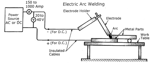
- In this process, a low voltage (20 to 40 V) and high current (150 to 1000 A) DC or AC Supply is used. One terminal (of power source) is attached to an electrode, while other terminal isattached to the work-piece.
- In DC Supply, Negative terminal is attached to electrode, while the Positive terminal is attached to Work-Piece.
- The electrode is first allowed to touch the work-piece to form an electric circuit and then Separated to maintain a gap of 3 - 6 mm. A large current tries to flow through air-gap in the form of an arc which produces the necessary heat (temperature in the range of 2400 4000 °C).
- This heat is enough to melt the base metal at the joint region. The additional metal if required, is supplied by the filler rod. The electrode is moved along the length of the work-piece to be welded.
|
Figure: Electric Arc Welding (SMAW)
Advantages of Electric Arc Welding
- The equipment (Set up) is portable and less expensive.
- Most versatile process, can be used for Welding of thick and thin sections.
- Welding of complicated shapes can be done.
- Welding can be done in any position of parts.
- Electric Arc Welding can produce good quality with better strength
Dis-advantages of Electric Arc Welding
- Process require filler material. It is slow process.
- Welding process is to be interrupted each time if consumable electrode is used.
- Welding Control is difficult.
- Quality of weld depends upon skill of the operator.
Applications of Electric Arc Welding
- Ship Building, Bridge Construction.
- Manufacturing of Manufacturing of Transmission Tower, Electric Tower.
- Manufacturing of Steel Furniture, Window Grill, and window or Door Frames.
- Manufacturing of Boiler, Pressure Vessel, Storage Tanks, and Pipelines.
- Complicated Structural Parts, Fabrication Job.
What is Flux?
- Flux is chemical used during Welding / Brazing / Soldering process.
- It is externally provided OR applied on area (region) to be joined.
- In ARC Welding with Consumable Electrode (That Process is called SMAW); an electrode is coated with Flux.
- Flux cleans the metal surface, (Remove the metal oxides and other impurities present on the surface).
- Protects the molten metal from oxidation and stabilizes the arc.
- Supplies some alloying elements to the weld.
5.1.15 Brazing
- Brazing is a joining process in which a filler metal is melted and distributed by capillary action between the flaying surfaces of the metal parts being joined.
- In brazing the filler metal has a melting temperature that is above 450C but below the melting point of the base.
Steps in Brazing Process
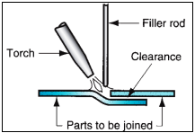
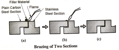
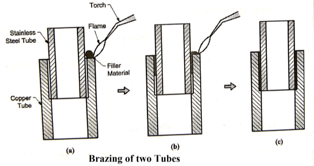
- Fig. below show the brazing process.
- Step 1: The two surfaces to be joined are cleaned and dried.
- Step 2: The flux is applied, by the fine brush, to the surfaces where filler material is to flow. The flux surveys the following purposes
- It removes the oxides and other impurities present-on the workpieces.
- It prevents the oxidation of the workpieces and filler materials. It melts at low temperature and forms a protective layer on the braze material.
- It lowers surface tension of the molten filler material and improves its flow into the joint.
- Step 3: The two work pieces to be brazed are fitted closely together. For the filler material to flow between the two surfaces by capillary action, a small clearance of 25 microns to 50 microns is provided between the two surfaces to be brazed.
- Step 4: A joint is heated to a brazing temperature (above 450°C) with the help of torch or in a furnace. There are two ways of adding the filler material
- A solid filler material may be preplaced on the work pieces and gets melted as the work pieces are heated; or
- A solid filler material may be applied to the work pieces after the brazing temperature is reached.
- Step 5: The molten filler material fills the joint between the two surfaces to be brazed, by capillary section& then it is allowed to solidify.
|
|
|
Advantages of Brazing
- Can join variety of dis-similar metals.
- Can join work piece of different thickness.
- Joint require very little OR no finishing
- Process can be suitable for mass production.
- Can produce pressure tight joints.
- Can produce Corrosion resistance joints
- The parts of then sheet which can not be joined by welding can be joined by brazing.
Limitations of Brazing
- Joint requires tightly mating parts.
- Strength of Brazed Joint is much lower than Welded Joint.
- Large sections cannot be joined.
- Brazed Joint can damage under high service Temp or high working Load.
- Filler material is costly.
- Color of the braze joint is (Dirty Yellow) different than base metal that may hamper looks of the joint.
Applications
- Brazing can join a large variety of dis-similar metals.
- Used to join Cast Iron, Steels, Cu and its alloy, Al and its alloy, Non-metal to metal.
- Heat Exchanger, Pipe fitting, Carbide Tip with Mild-Steel Shank, Steam Turbine, and Electric repair work etc.
5.1.16 Soldering
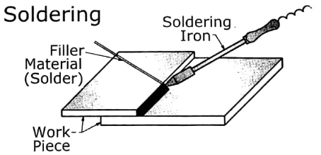
- Soldering is the process of joining two workpieces, made of similar or dissimilar materials, by heating them to a specified temperature below 450°C and using a non-famous filler material.
- The soldering is similar to brazing except that the filler material has a melting temperature below 450°C.
- Commonly used filler material (solder) for soldering: tin-lead alloy.
Steps in Soldering Process
- Step 1: The workpieces to be joined are first cleaned.
- Step 2: The two workpieces to be soldered are fitted closely together.
- Step 3: The soldering iron, which is heated electrically, is dipped in the flux. The heat is applied to the joint by the heated soldering iron. The flat face of the soldering iron is held directly against joint assembly so that the heat is most effectively transmitted.
- Step 4: Due to heat, the flux melts and cleans the oxide film on the surface.
- Step 5: The solder or filler material is applied at the joint. The solder or filler material melts and fills the joint between the two surfaces to be soldered, by capillary action. It is then allowed to solidify.
|
|
Advantages of Soldering
- Simple and low-cost method.
- Can join variety of dis-similar metals.
- Can join work piece of different thickness.
- Joint do not require any finishing
Limitations of Soldering
- Strength of Soldered Joint is Poor than Brazed Joint. So the Joint cannot take any Load.
- Large sections cannot be joined.
- Lead in the filler material is toxic.
Applications
- Printed Circuit Boards,
- Electric Circuits, Joining of Wires,
- Thin Sheets, Jewelry Components
5.1.17 General Procedure in Brazing and Soldering
- Clean the area (region) to be joined.
- Apply the flux (in the form of paste or powder) on the area to be joined.
- Align the two parts (put them together in desired position)
- Heat the joint area (region) with the help ofGas Flame or in furnace (For brazing) OR using Soldering Iron (For Soldering).
- Provide the Filler material at the joint. Filler material melts and flow in the gap of between two parts, fills the gap (or space or joint region) by capillary action. It is then
allowed to solidify. Please Note that: Base metal is not melted.
5.1.18 Comparison of Welding, Brazing & Soldering
Parameter | Welding | Brazing | Soldering |
Temperature | > 1500°C | Above 450°C | Below 450°C |
Melting of work piece | Yes | No | No |
Heating of work piece | By electrical energy or gas flame | Gas flame of in furnace | Gas flame or electrical soldering iron |
Strength of joint | High | Less than welded joint | Very low. |
Surface finish | Not very good | Good | Not very good |
Cost | Costly | Costly | Cheap |
Base metals | Similar metals | Similar or dissimilar metals | Similar or dissimilar metals |
Material thickness | Not Possible for thin sheets | Possible for thin sheets | Possible for thin sheets |
Filler Material | Same as base metal | Braze Material or | Solder which is an alloy ofTin-Lead OR alloy ofAntimony, Zinc, Aluminium |
5.1.19 Introduction
Machine Tools are power driven machines used for:
- Metal Cutting Processes, For Example: Lathe Machine, Drilling Machine, Milling (Removing material from work-Piece in the form of chip) &
- Sur-face Finish Processes, For Example: Grinding Machine (Imparting good surface finish with negligible material removal)
- A machine-tool can machine / produce Flat, Cylindrical, Spherical (OR Combination of two or all) Surfaces / Shapes.
Every Machine Tool has to perform following Functions:
- Hold, Support, and Guide the Work piece to be machined.
- Hold, Support, and Guide the Cutting Tool for machining.
- Provide Motion to Work-Piece OR Cutting Tool OR Both of them.
- Control / Regulate the Cutting Speed and Feed between Work-Piece and Cutting Tool.
Feed: The Movement of the tool relative to the work-piece is known as Feed.
5.1.20 Introduction
- Lathe is considered as one of the oldest machine tools and is widely used in industries.It is called as mother of machine tools.
- It is said that the first screw cutting lathe was developed by an Englishman named Henry Maudslay in the year 1797. Modern high speed, heavy duty lathes are developed based on this machine.
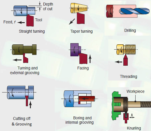
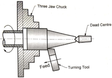
- The primary task of a lathe is to generate cylindrical workpiece. The process of machining a workpiece to the required shape and size by moving the cutting tool either parallel or perpendicular to the axis of rotation of the workpiece is known as turning.
|
5.1.21 Working Principle
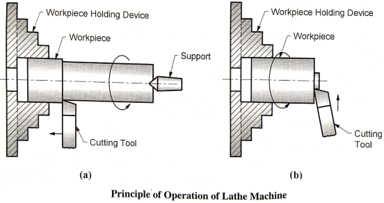
- Cylindrical Work-Piece is held between TWO Strong & Rigid Supports called as Centres. (Chuck or Face Plate of Head-stock and Dead Centre of Tail-stock).
- Cutting Tool is rigidly held and supported in a Tool Post.
- Work-Piece revolves about its own axis (Which is same as Spindle Axis)
- The tool is fed against the revolving Work-Piece in Longitudinal, Cross or Angular Direction.
|
|
The Lathe Tool can have motion in following direction.
- Longitudinal (Along the Spindle Axis or Cylindrical Work-Piece Axis)
- Cross (Perpendicular to Spindle Axis or Cylindrical Work-Piece Axis)
- In Above diagram, Depth of Cut in Turning process = ( D - d ) / 2
Where, D = Uncut Dia, d=Cut Dia. of Work Piece.
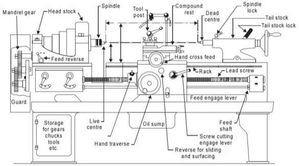
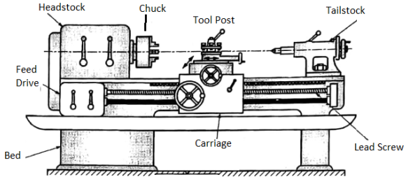
5.1.22 Basic Elements of Lathe Machine
|
|
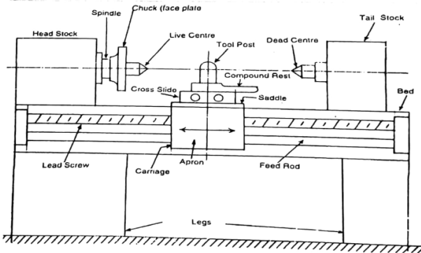
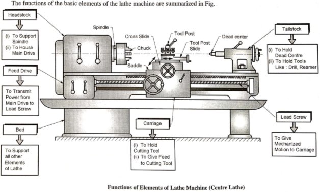
Figure: Lathe Machine Parts
- Some important parts of a Lathe are listed below.
- Bed
- Headstock
- Spindle
- Tailstock
- Carriage
- Saddle
- Apron
- Cross slide
- Compound Rest
- Compound Slide
- Tool Post
6. Feed Mechanism
7. Lead screw
8. Feed rod
9. Thread Cutting Mechanism
|
5.1.23 Construction and working:
Bed
- Bed is mounted on the legs of the lathe which are bolted to the floor. It forms the base of the machine. It is made of cast iron and its top surface is machined accurately and precisely. Usually it is used for the supporting the all the parts of lathe.
Headstock
- Headstock is mounted permanently on the inner guideways at the left hand side of the leg bed.
- The headstock is used to house the spindle and the main drive (mechanism for driving the spindle at multiple speeds).
Spindle
- The spindle rotates on two large bearings housed on the headstock casting. A holeextends through the spindle so that a long bar stock may be passed through the hole.
- The front end of the spindle is threaded on which chucks, faceplate, driving plate and catch plate are screwed. The front end of the hole is tapered to receive live center which supports the work.
Tailstock
- Tailstock is located on the inner guide ways at the right side of the bed opposite to the headstock. The body of the tailstock is bored and houses the tailstock spindle or ram.
- The spindle moves front and back inside the hole. The spindle has a taper hole to receive the dead centre or shanks of tools like drill or reamer. If the tailstock hand wheel is rotated in the clockwise direction, the spindle advances.
- It is used to hold the dead centre and the tools like drill, reamer etc.
Carriage
- Carriage is located between the headstock and tailstock on the lathe bed guideways. It can be moved along the bed either towards or away from the headstock.
- It is used to hold, support, move and control the cutting tool.
- The parts of the carriage are
- Tool Post: It is mounted on Compound rest, its function is to hold the tool.
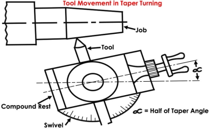
- Compound Rest: It is mounted on Cross Slide, it is used for taper Turning operation.
- Cross Slide: It is mounted on Saddle, it gives cross-motion to carriage /cutting tool.
- Saddle: It is mounted on lathe bed which moves along lathe bed guide-ways
- Apron: It is bolted to the Front of Saddle. It contains the necessary mechanism for longitudinal movement of carriage.
Feed Drive
- It is used to transmit motion from main drive to lead screw.
Lead Screw
- It is used to give the mechanized motion to the carriage.
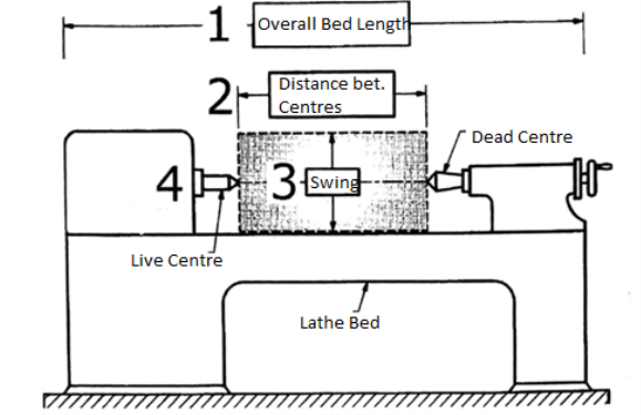
5.1.24 Lathe Machine Specifications
- Overall Length of Bed: It is total length of bed.
- Distance between Centres: It is the max length of the work-piece that can be mounted between centres (Live Centre & Dead Centre). OR It is distance between Live Centre & Dead Centre.
- Swing: It is the max diameter of the work-piece that can be machined without touching the bed.
- Min and Max Spindle Speed: It is the min and max speed of the spindle.
|
Figure: lathe Specifications
5.1.25 Operations performed in a lathe:
Various operations are performed in a lathe other than plain turning. They are
- Facing
- Turning
- Eccentric turning
- Taper turning
- Chamfering
- Grooving and parting off
- Forming
- Knurling
- Thread cutting
- Drilling
- Reaming
- Boring
- Tapping
|
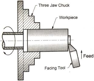
- Facing
- Facing is the operation of machining the ends of a piece of work to produce flat surface.
|
- Facing tool is moved perpendicular to axis (of Spindle OR axis of work-piece) by using Cross Slide.
2. Turning
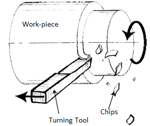
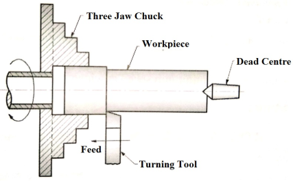
- Turning in a lathe is to remove excess material from the workpiece to produce a cylindrical surface of required shape and size.
|
- Turning is process of removing material from Cylindrical Surface of Work-Piece to reduce its Diameter.
- Turning tool is held in tool-post. Tool Motion is parallel to work piece axis or spindle axis.
3. Eccentric turning
|
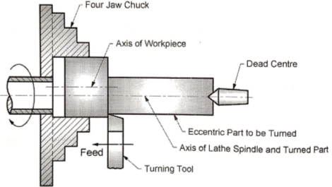
- If a cylindrical work piece has two separate axes of rotating, one being out of centre to the other, the work piece is termed as eccentric and turning of different surfaces of the work piece is known as eccentric turning.
- The distance between the axes is known as offset. Eccentric turning may also be done on some special machines.
- If the offset distance is more, the work is held by means of special centers. If the offset between the centers is small, two sets of centers are marked on the faces of the work.
- The work is held and rotated between each set of centers to machine the eccentric surfaces.
4. Taper Turning
- Taper: A taper may be defined as a uniform increase or decrease in diameter of a piece of work measured along its length.
- Cutting tool is moved at an angle to the Work piece axis by using Compound rest.
- Half Taper Angle (α): tan-1 (D - d)/2L.
- Where, D = Max dia., d = min dia., L = Length of taper
|
|
Figure: Taper Turning
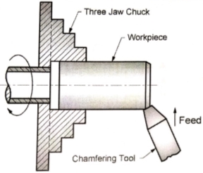
5. Chamfering
- Chamfering is the operation of beveling the extreme end of the work piece. Here sharp ends or a work piece are removed.
|
- Chamfering is provided for 1) to avoid injuries while work-piece handling & 2)to enhance (aesthetic) looks.
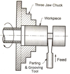
6. Grooving
- Grooving is the process of cutting a narrow groove on the cylindrical surface of the work piece.
|
|
- It is often done at end of a thread or adjacent to a shoulder to leave a small margin. The groove may be square, radial or beveled in shape.
- In grooving operation the shape of the tool is reproduced on the work piece: hence, this process is also known as form turning operation.
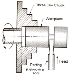
7. Parting or Cutting off
- Parting is the process of cutting awork-piece into two parts. Tool used is called Parting Tool.
|
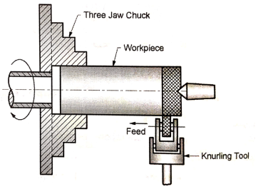
8. Knurling
- Knurling is the process of embossing a diamond shaped pattern on the surface of the work piece.
|
- The knurling tool holder has one or two hardened steel rollers with edges of required pattern.
- The tool holder is pressed against the rotating work. The rollers emboss the required pattern.
- The tool holder is fed automatically to the required length.Knurls are available in coarse, medium and fine pitches. The patterns may be straight, inclined or diamond shaped.
- Purpose of Knurling is to provide a non-slip grip on the surface, to give decorative look.
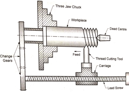
9. Thread cutting
- Thread cutting is one of the most important operations performed in a lathe.
- The process of thread cutting is to produce a helical groove on a cylindrical surface by feeding thetool longitudinally.
|
- To cut thread a definite relation between rotary motion of work-piece and linear motion of tool is required. It is achieved by engaging Lead Screw with Split-Nut of carriage. Thus Carriage will be given auto motion through lead screw.
- In threading operation, the tool motion is longitudinal i.e. parallel to the axis of the lathe spindle. For one rotation of work piece, the tool automatically (mechanically) travels by a distance equal to the pitch of the threads.
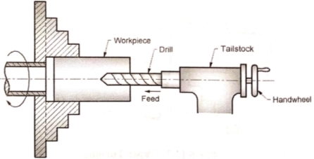
10. Drilling
- In a drilling operation, the work piece is held in a chuck while the drill is held in the tailstock. The drill is then fed against the rotating work piece by rotating the handle of the tailstock in clockwise direction.
- Once the hole is drilled, the drill is withdrawn by rotating the handle of the tailstock in the anti-clockwise direction
|
- In this case, the work piece is rotating and the drill tool is moved or fed along the length of work piece.
11. Reaming
- Reaming is the process of finishing the cylindrical hole in the work-piece.
- Work-piece is held in Chuck and Reamer tool is held in Tail-stock. Work-piece rotates and Reamer moves along the axis (in linear direction).
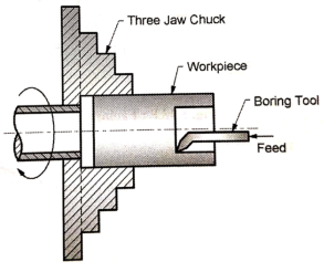
12. Boring
- Boring is process of enlarging the already existing hole in the work-piece. Tool used is called boring tool.
|
- Tool is held in tool-post and moves parallel to the axis (of spindle or axisof work-piece).
5.1.26 Introduction
- Drilling: Process of producing cylindrical hole in the work-piece is called as Drilling.
- Drill: A multi-point cutting tool used to make cylindrical holes In work-piece.Drill is made of harder material (High Speed Steel) than that of work-piece.
- Drill is press fitted in Drill Chuck.
- Material of Drill: HSS High Speed Steel, Alloy Steel, High Carbon Steel etc.End Shape of the drill tool is Conical in Shape which is needed to initiate a hole inmaterial.
5.1.27 Working Principle
- A work-piece is firmly clamped on Work-Table or Base. Work-piece is stationary.The Rotating Drill is fed against the stationary work-piece by hand feed or power feedarrangement. During the process material is removed in the form of chip.
5.1.28 Types of drilling machines
- Drilling machines are manufactured in different types and sizes according to the type of operation, amount of feed, depth of cut, spindle speeds, method of spindle movement and the required accuracy.The different types of drilling machines are:
- Portable drilling machine (or) Hand drilling machine
- Sensitive drilling machine (or) Bench drilling machine
- Upright drilling machine
- Radial drilling machine
- Gang drilling machine
- Multiple spindle drilling machine
- Deep hole drilling machine
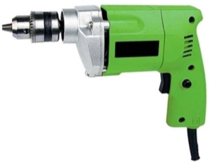
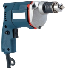
5.1.29 Portable drilling machine
- Portable drilling machine can be carried and used anywhere in the workshop. It is used for drilling holes on workpiece in any position, which is not possible in a standard drillingmachine.
|
- The entire drilling mechanism is compact and small in size and so can be carried anywhere.
- The motoris generally universal type. Portable drilling machines are operated at higher speeds.
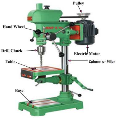
5.1.30 Sensitive drilling machine
- It is designed for drilling small holes at high speeds in light jobs.High speed and hand feed are necessary for drilling small holes.
|
- The base of the machine is mounted either on a bench or on the floor by means of bolts and nuts.The drill is fed into the work purely by hand.
- The operator can sense the progress of the drill into the work because of hand feed. The machine is named so because of this reason. A sensitive drilling machine consists of a base, column, table, spindle, drill head and the driving mechanism.
- The base made of cast iron may rest on a bench, pedestal or floor depending upon the design. Larger and heavy duty machines are grounded on the floor.
- The column is mounted vertically upon the base. It is accurately machined and the table can be moved up and down on it.
- The drill spindle, an electric motor and the mechanism meant for driving the spindle at different speeds are mounted on the top of the column. Power is transmitted from the electric motor to the spindle through a flat belt or a ‘V’ belt.
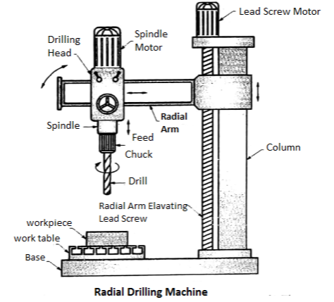
5.1.31 Elements of Radial Drilling Machine
- Base
- Work Table (has T Slots) which is mounted on Base
- Column
- Radial Arm (Supported on Column) can be moved Up-Down along the column axisand Swing or Swivel [means Turning upto 180°] about column axis.
- Drill Head is mounted on radial arm which can move along the length of Radial arm. It consists of a) Drive mechanism (which provided Rotary motion to drill tool)b) Feed Mechanism (Which provides Linear, Up & Down motion to the drill tool)
- Spindle (Driven by electric motor through Gear Box)
- The radial drilling machine is intended for drilling on medium to large and heavy work pieces. It has a heavy round column mounted on a large base.
- The column supports aradial arm, which can be raised or lowered to enable the table to accommodate workpieces of different heights.
- The arm, which has the drill head on it, can be swung around to anyposition. The drill head can be made to slide on the radial arm. The machine is named so because of this reason. It consists of parts like base, column, radial arm, drill head and driving mechanism.
5.1.32 Construction and working
- Base: The base is a large rectangular casting and is mounted on the floor of the shop. Its top is accurately finished to support a column at one end and the table at the other end. ‘T’-slots are provided on it for clamping workpieces.
- Column: The column is a cylindrical casting, which is mounted vertically at one end of the base.It supports the radial arm and allows it to slide up and down on its face.
- The vertical adjustment of the radial arm is effected by rotating a screw passing through a nut attached to the arm. An electric motor is mounted on the top of the column for rotating the elevating screw.
|
Fig.: Radial Drilling Machine
- Radial arm: The radial arm is mounted on the column parallel to the base and can be adjusted vertically. The vertical front surface is accurately machined to provide guideways for the drill head.
- The drill head can be adjusted along these guideways according to the location of the work. In some machines, a separate motor is provided for this movement. The arm may be swung around the column. It can also be moved up and down to suit workpieces of different heights.
- Drill head: The drill head is mounted on the radial arm and houses all mechanism for driving thedrill at different speeds and at different feed. A motor is mounted on top of the drill head forthis purpose.
- To adjust the position of drill spindle with respect to the work, the drill headmay be made to slide on the guideways of the arm. The drill head can be clamped in positionafter the spindle is properly adjusted.
5.1.33 Drilling machine operations
- Though drilling is the primary operation performed in a drilling machine, a number ofsimilar operations are also performed on holes using different tools. The different operationsthat can be performed in a drilling machine are:
- Drilling
- Reaming
- Boring
- Counterboring
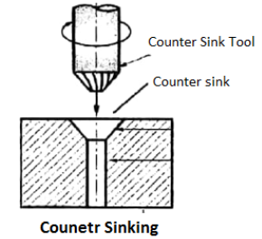
- Countersinking
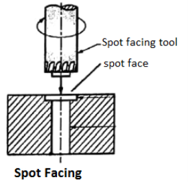
- Spot facing
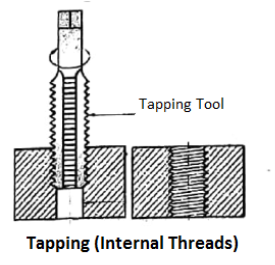
- Tapping
|
|
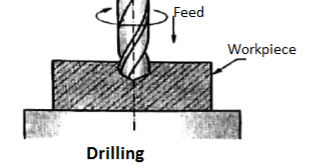
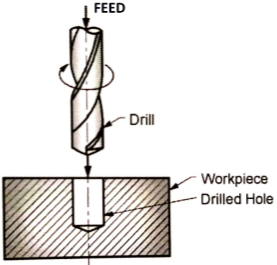
- Drilling
- Drilling is the operation of producing a cylindrical hole of required diameter and depth by removing metal by the rotating edge of a cutting tool called drill.
| |
| |
- Drilling does not produce an accurate hole in a workpiece. The internal surface of the hole generated by drilling becomes rough and the hole is always slightly oversize due to vibration of the spindle and the drill.
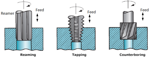
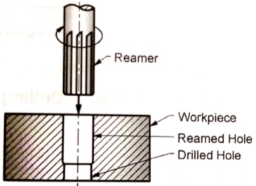
2. Reaming
- The size of hole made by drilling may not be accurate and the internal surface will notbe smooth. Reaming is an accurate way of sizing and finishing a hole which has been previously drilled by usingmulti-point cutting tool known as reamer.
|
- The surface obtained by reaming will be smoother and the size accurate. The speed of the spindle is made half that of drilling.
- Reaming removes very small amount of metal (approx 0.375 mm). In order to finish a hole and bring it to the accurate size, the hole is drilled slightly undersize.
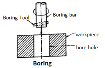
3. Boring
- Boring is the operation enlarging the diameter of the previously made hole. It is done for the following reasons.
|
a) To enlarge a hole by means of an adjustable cutting tool. This is done when a suitable sized drill is not available or the hole diameter is so large that is cannot be ordinarily drilled.
b) To finish a hole accurately and bring it to the required size.
c) To machine the internal surface of the hole already produced in casting.
d) To correct out of roundness of the hole.
e) To correct the location of the hole as the boring tool follows independent path with respect to the hole.
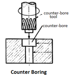
4. Counter boring
- Counter-boring is the process of enlarging the existing hole to a larger diameter and making the surface at the bottom of the larger diameter flat.
- Counterboring is the operationof enlarging the end of the holecylindrically. The enlarged hole formsa square shoulder with the original hole.
- This is necessary in some casesto accommodate the heads of bolts,studs and pins. The tool used forcounter boring is known as counterbore.
|
- The counterbores are made withcutting edges which may be straight orspiral. The cutting speed forcounterboring is atleast 25% lesserthan that of drilling.
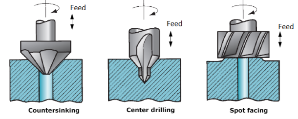
5. Countersinking
- Countersinking is the operation of making a cone shaped enlargement at the end of thehole. The included angle of the conical surface may be in the range of 60° to 90°.
- It is usedto provide recess for a flat headed screw or a counter sunk rivet fitted into the hole. The toolused for counter sinking is known as a countersink.
|
- It has multiple cutting edges on its conical surface. The cutting speed for countersinking is 25% lesser than that of drilling.
6. Spot facing
|
- Spot facing is the process of enlarging the existing hole to a larger diameter and making the surface at the bottom of the larger diameter flat such that the depth of the enlarged hole is sufficient to provide a seat for the washer. Spot-facing is similar to the counter-boring except in spot-facing the depth of the enlarged hole is very small.
- Spot facing is the operationof smoothing and squaring thesurface around a hole.
- It is doneto provide proper seating for a nutor the head of a screw or the washer. Acounter bore or a special spotfacing tool may be employed forthis purpose.
7. Tapping
- Tapping is the operation of cutting internal threads by means of a cutting tool called‘tap’. Tapping in a drilling machine may be performed by hand or by power.
|
- When the tapis screwed into the hole, it removes metal and cuts internal threads which will fit into externalthreads of the same size.
Reference Books
1. Khan, B. H., “Non Conventional Energy Sources, Tata McGraw-Hill Publisher Co. Ltd.
2. Boyle, Godfrey, “Renewable Energy”,2nd Ed., Oxford University Press
3. Khurmi, R.S. ,and Gupta, J. K.,“A Textbook of Thermal Engineering”, S. Chand & Sons
4. Incropera, F. P. and Dewitt, D.P., (2007), “Fundamentals of Heat and Mass Transfer, 6th Ed., John Wiley and Sons, USA
5. Groover,Mikell P., (1996), “Fundamentals of Modern Manufacturing: Materials, Processes, and Systems”, Prentice Hall, USA
6. Norton, Robert L., (2009), “Kinematics and Dynamics of Machinery”, Tata McGrawHill
7. Cleghorn, W. L., (2005), “Mechanisms of Machines”, Oxford University Press
8. Juvinal, R. C., (1994), “Fundamentals of Machine Component Design”, John Wiley and Sons, USA
9. Ganeshan, V., (2018), “Internal Combustion Engines”, McGraw Hill
10. Anderson, Curtis Darrel and Anderson,Judy, (2010), “Electric and Hybrid Cars: A History”, 2nd Ed., McFarland

