UNIT-6
ENGINEERING MECHANISMS & THEIR APPLICATIONS IN DOMASTIC APPLIANCES
EQUIPMENT TERMINOLOGY
The technical specifications of any equipment or product indicates the net of performance parameters and physical parameters meet by or exceeded by that equipment or product.
Need of Technical Specifications:
- Technical specifications describe the product completely.
- Technical specifications indicate the quality and performance of product.
- Buyer can compare similar products available in market using technical specifications.
- Technical specifications help user / buyer to find out whether the product meets their requirements or not.
- It defines the requirements for installation of product so that the buyer can make provisions.
- Technical specifications give indication of running cost and power consumption of the product.
Input:
- Input to an equipment or product or machine is nothing but an energy supplied to it.
- The Input can be given in different forms which are given below.
- Electric energy (Single phase A.C., Three phase A. C., D.C. supply): Refrigerators, Pumps, water cooler, lathe machine are supplied electrical energy as an input.
- Chemical energy of fuel (diesel, petrol, kerosene or gas): Motorcycle, bus, truck, car runs on the chemical energy supplied by the fuel as an input.
- Solar energy: Solar Water Heater, Solar Lamps uses solar power.
- Human power: Wheel chair, bicycle, punching machine, stapler uses energy supplied by human.
Output:
- Output of any equipment or product or machine is the work done by it.
- The output can have different forms as given below.
- Tractive effort:Motorcycle, bus, truck, car
- Raising or lifting load: Cranes, Lifts etc.
- Increasing pressure:Pump, Compressors
- Cooling effect: Refrigerators, AC
- Heating effect: Electric Geyser, Solar water Heater, Electric Iron etc.
|
1. Belt Drive
2. Chain Drive
3. Gear Drives
4. Springs
5. Levers
6. Pump
7. Compressor
8. Blowers
9. Valves
DRIVES
- Drives are defined as the mechanisms used for transmitting power and motion from prime mover (Power-source) to the driven machine. In modern design, prime-movers like Electric-motor, I C Engines, Steam turbines and Gas Turbines are becoming compact, lightweight and having very high speed of rotation.
- This high speed of the prime mover is not always suitable for every machine. Thus various drives / power transmission devices are used to transmit power from prime mover and to get desired speed & torque for the driven machine.
- The power transmission and speed reduction between the prime mover and the machine being driven can be achieved by using the various power transmission devices or drives given below:
- Belt Drives
- Chain Drives
- Rope Drives
- Gear Drives
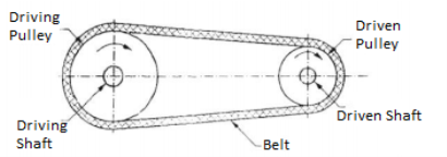
- Belt drive is used to transmit power from one shaft to another shaft by using pulleys which rotate at same speed or at different speed. Belt drives are used when shafts are at considerable distance apart from each other.
- A belt drive consists of three elements: 1) Driver Pulley (Also known as Driving or Head Pulley) 2) Driven Pulley (Also known as Tail Pulley) 3) Belt
Where,
From equation 1 & 4,
|
Types of Belts
• Flat Belt Drive
• V Belt Drive
• Timing/Toothed Belt
|
- Flat Belt Drive
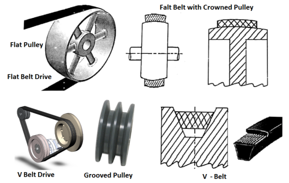
- Flat belts are as show in the figure have rectangular cross section. In flat belts the width of belt is substantially higher than thickness of belt. These belts have joint.
|
Figure: Flat belt Pulley
- They can be used to transmit a moderate amount of power from one pulley to another over long Centre distances when the two pulleys are at a distance of up to 15 meter fromeach other.
- In flat belt drives, the pulleys are provided with proper crowning to avoid coming off of the belt from the pulley. Such pulleys are known as crowned pulleys.
- Desired Properties of the belt material : 1) High Coefficient of Friction 2) Flexibility 3) Durability 4) High Strength
- Material for Flat belt: Rubber, Leather, Fabric etc.
Advantages of Flat Belt Drive:
1) Can transmit power over long Centre distance upto 15 meter.
2) Relatively cheap and easy to maintain.
3) High efficiency upto 98%.
Limitations of Flat Belt Drive:
1) Slip is more. They are large in size and occupy more space.
2) Cannot be used for short centre distances.
3) They cannot transmit high power.
4) Their operation is noisy.
Applications of flat belt drive:
1) To drive Flour mill, Stone Crushers and industrial application.
Types of Flat Belt:
- Open Belt Drive
- Cross Belt Drive
- Compound Belt Drive
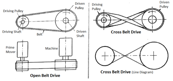
- Observe various Figures of belt drives given below.
|
|
|
Open Belt Drive:
- In Open belt drive, both the pulleys rotate in same direction. It is used to transmit moderate power when both shafts are parallel and centre distance is upto 15 meter.
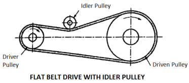
- Open belt drive with an idler pulley is used to obtain desired belt tension, high speed ratio and higher power transmission.
- The belt tension can be adjusted by changing the position of idler pulley.
- Used when shafts are parallel.
Cross Belt Drive:
- In Cross belt drive, both the pulleys rotate in opposite direction.It is used to transmit power when both shafts are parallel and centre distance is shorter.
- Due to more Contact with pulley, Cross belt gets more frictional grip over pulley so it cantransmit more power as compared to Open belt drive.
- However, cross belt rub against each other during operation and hence there will be
- Excessive wear / tear which reduces life of the belt.
- Use: The crossed belt drive is used when the shafts are parallel and centre distance is shorter.
Open Belt Drive with Idler Pulley
- The open belt drive with an idler pulley is used to obtain the high velocity ratio and the desired belt tension.
- Used when shafts are parallel and when an open belt drive cannot be used.
Compound Belt Drive:
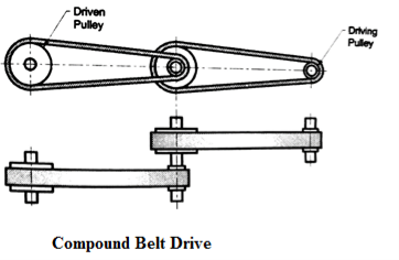
- A compound belt drive gives relatively high reduction ratio.
- Use: A compound belt drive is used when the power is to be transmitted from one shaft to another through a number of intermediate pulleys.
|
2. V- Belts Drive:
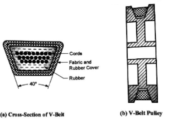
- V belts, as Shown in Figure are having Trapezoid cross section. In these drive, Pulleys are provided with V Shaped Groove to accommodate V belt. These pulleys are called as Grooved Pulleys or Sheaves.
|
Figure: V – Belt Cross Section and Pulley
- Normally included angle of V belt is 40° while for grooved pulley angle is 38°. Due to wedging action, they can transmit large power when two pulleys are relatively close to each other.
Advantages of V - Belt Drive:
1) Due to wedging action, they transmit large power as compared to flat belt drive and also Due to wedging action, slip is less.
2) Used for short centre distance which results in compact construction.
3) With multiple drive, V belt can transmit very large power.
4) They permit high speed ratio (reduction ratio) even upto 7.
5) V belts are endless (has no joint), so the operation is smooth and quiet even at very high speed.
Limitations of V Belt Drive:
1) Efficiency of V-belt is less as compared to flat belt drive. It is in the range of 80 % to 96 %.
2) They cannot transmit power over long centre distance.
3) They are costly as compared to flat belt drive.
Applications of V Belt Drive:
1) V belts are used to drive Pump, Air Compressor, machine tools, Farm Machinery and automobile engine accessories.
3. Timing Belt:
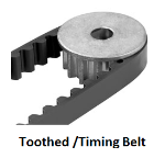
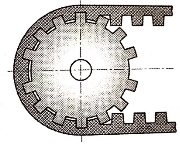
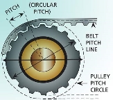
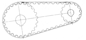
- Timing belt is toothed belt transmit the power by teeth rather than friction hence there will be no slip.
- Timing belts require toothed wheel or sprockets.
|
| |
| |
|
Figure: Timing Belt
Limitations of timing Belt:
1) They cannot transmit large power.
2) They are costly.
Comparison between Flat belt and V - belt drive
Sr. No. | Parameter | Flat Belt Drive | V – Belt Drive |
1 | Cross Section | Rectangular | Trapezoidal |
2 | Joint | Flat belt have joint. | V belts are joint-less / endless. |
3 | Construction of Pulley | Require Flat Pulley with simple construction. | Require V grooved pulley which has complicated construction. |
4 | Centre Distances | Flat belt drives are used to transmit power over long distances upto 15 meter. | V - Belt drives are used to transmit power over short centre distances upto 3 meter. |
5 | Slip | Slip is more. | Slip is less due to wedging action. |
6 | Power Transmission | Not useful for large power transmission. | Due to wedging action, useful for large power transmission. |
7 | Operating Speed | Not useful for high speed application. | Can be used for high speed application. |
8 | Speed ratio | Not useful for high speed ratio.(Limited Upto 3to 4) | Can be used for high speed ratio.(Upto 7) |
9 | Efficiency | High (Upto 98%) | Low (80% - 96%) |
10 | Operation | Noisy Operation | Smooth & Quite Operation. |
11 | Cost | Cheaper | Costlier. |
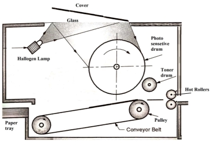
- In photocopier machine conveyor belt is used for carrying the paper from paper tray to the hot rollers.
- When document is placed on glass, beam of halogen light scans the document. The light gets reflected and electrical shadow of document (negatively charged image) is formed on photosensitive drum.
|
Figure: Photocopier
- As photosensitive drum rotates, it carries electrical shadow of document (negatively charged image) towards toner.
- The toner is positively charged. The positively charged toner ink sticks to negatively charged image on the drum surface.
- Thus, inked image of document is formed on the surface of the drum.
- The paper is carried by the conveyor belt from paper tray. The paper is given electric charge. Therefore, inked image from the surface of the drum is transferred to the paper on conveyer belt.
- When paper passes through two hot rollers, heat and pressure from rollers permanently fuses the tonner particle on the paper.
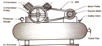
- In air Compressor, V - belt is used for transmitting the power from electric motor to crankshaft of the compressor.
|
- One pulley with v-groove is mounted on the crankshaft of compressor while another pulley is mounted on the shaft of electrical motor as shown in above figure.
- In case of belt drive, while transmitting motion, slipping may occur (non-positive drive). Hence, to avoid slipping steel chains are used.
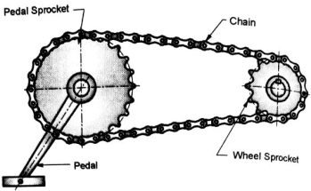
- A chain drive consists of an end-less chain running around two sprocketwheels (Sprockets are toothed wheels) as shown.
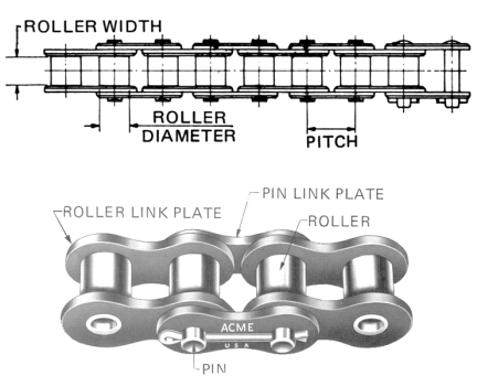
- Chains are made up of number of rigid links which are hinged together by using pin joints, to provide the necessary flexibility of wrapping around the drivingand driven wheels.
- These wheels have projecting teeth of special profile which fits into the corresponding recesses in the chain link as shown. The toothed wheels are called as sprockets.
|
|
Figure: Chain Drive
- The chain drive is commonly used to transmit motion from one shaft to other shaft which placed at relatively short centre distance.
- The chain wraps around the sprockets not in the form of circle but in the form of polygon. The links of chain form sides of polygon. Due to this, for a constant driving sprocket speed, there is a fluctuation in driven sprocket speed. It is called as polygon effect.
Advantages of Chain drive
1) Chain does not slip over sprocket. Chain drive is positive drive.
2) Chain drive can be used for short as well as long centre distances.
3) Chain drive can transmit large power over long distances.
4) Chain drives are compact as compared to belt drive.
5) Chain drive can allow /easily accommodate any misalignment between shafts.
6) Chain drive has high driving efficiency as high as 98%.
7) Chain drives are less expensive than gear drive.
Limitations of Chain drive
1) Due to polygonal effect, the chain drives are not suitable when precise (or accurate/exact) output motion is required. Gear drive produces very much precise and accurateoutput motion hence they are used in hand-watches.
2) Chain drive need regular periodic lubrication and slack (Length) adjustment.
3) They operate with noise.
Applications of Roller Chain drive
1) To drive Bicycle, Motorcycle, Agricultural machinery, Rolling mills, Conveyers etc.
Comparison between Belt and Chain drive
Sr. No. | Parameter | Belt Drive | Chain Drive |
1 | Type of Drive | Non Positive (Always have some slip) | Positive (No slip) |
2 | Elements of Drive | Belt, Driving & Driven Pulley | Chain, Driving & Driven Sprocket. |
3 | Polygonal effect | Absent | Present |
4 | Initial Tension | Required | Not Required |
5 | Lubrication | Not Required | Periodically Required |
6 | Power Transmission Capacity | Low | Moderate |
7 | Space Requirement | More | Less |
8 | Transmission Efficiency | Low | High |
9 | Operation | Noisy Operation | Smooth & Quite Operation. |
10 | Cost | Cheaper. | Costlier. |
|
Figure: Bicycle
- In bicycles, the chain drive is used for transmitting the power or torque from pedals to rear wheel.
- The size of pedal sprocket is larger than the size of wheel sprocket. Hence, speed is increased from pedals to wheel.
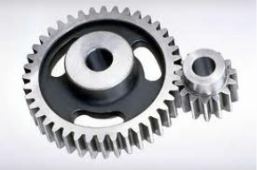
- Gears are defined as the toothed wheels which can transmit power and motion from one shaft to another shaft by means of successive engagement of teeth.
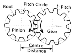
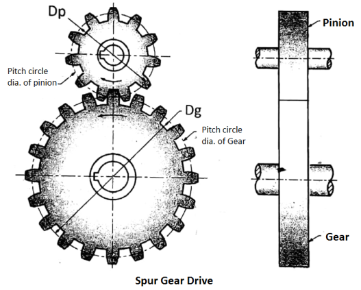
- Gears operate in pairs, the smaller is called pinion and the larger is called Gear. They always rotate in opposite direction. Gear tooth profile is either involute or cycloid.
- In precision machines and mechanisms like watch gear mechanism, definite speed ratio is required which is obtained by using gear drive or gear wheels.
- Gear drive is a positive drive and it is used when the distance between the driver and follower is very small.
| ||
| ||
The pinion and gear rolls over each other, without slipping, along the pitch circle. Hence pitch line velocity of pinion and gear is same.
It is the ratio of the pinion speed to gear speed. OR ratio of number of teeth on gear to number of teeth on pinion.
The efficiency of all gear drives is about80% but in actual practice it is assumed as 100%. Hence power of pinion and gear is same. Let,
| ||
- Functions of Gear:
1) To increase the torque and reduce the speed from the input shaft to the output shaft.
2) To increase the speed and reduce the torque from the input shaft to the output shaft.
3) To transmit the power from one shaft to another shaft.
4) To change the direction of rotation form one shaft to another shaft.
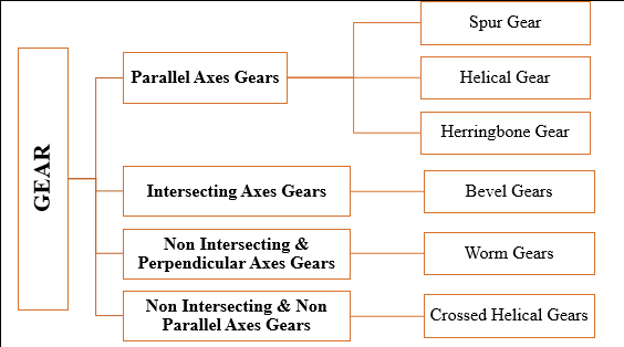
Types of Gears:
|
- Spur Gear:
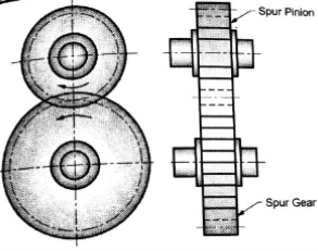
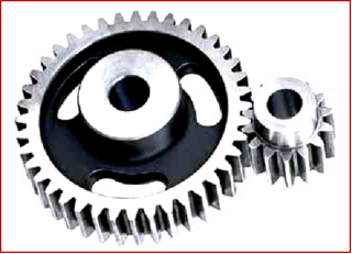
- Spur gears are used for transmitting power or motion between two parallel axes of shaft. In spur gears the teeth are parallel to the axis of gear.
- Applications of Spur Gear: machine tool gearbox, automobile gear box, industrial gear box, clocks and watches etc.
|
|
Figure: Spur Gear
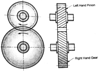
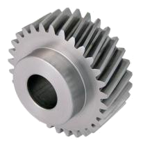
2. Helical Gear:
- In helical gears, the teeth are at an angle. Known as helix angle with the axis of the gear.
- The helix angles of gear and pinion are same in magnitude but of opposite hands. A right-hand gear meshes with a left-hand pinion or vice-versa.
- Applications of helical gears: The helical gears are used for transmitting power / motion between two parallel axes shafts
| |
| |
Figure: Helical Gear
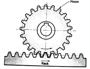
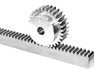
3. Rack and Pinion
- Rack is a straight line gear. In rack and pinion, the straight sided rack meshes with the pinion Rack converts rotary motion of pinion into alinear motion of the rack or vice versa.
- Applications of rack and pinion: Used in lathe machine, drilling machine, milling machine and door closure mechanism.
| |
| |
Figure: Rack and Pinion
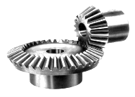
4. Bevel Gears
- To connect two non-parallel shafts whose axis are interesting.
|
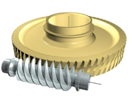
5. Worm and worm wheel
- To transfer rotating motion between two shaft whose axis non-parallel, non-intersecting
|
- Any combination of gears used for transmitting motion and power one shaft to another shaft is called a gear train.
- Functions of Gear Trains:
- to reduce the speed from the driving (input) shaft to the driven (output) shaft ;
- to increase the speed from the driving (input) shaft to the driven (output) shaft;
- to keep the speed same from the driving (input) shaft to the driven (output) shaft.
Types of Gear Trains:
1. Simple Gear Train
2. Compound Gear Train
3. Reverted Gear Train
4. Epicyclic Gear Train
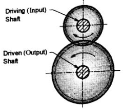
- Simple gear train without idler:
- In this arrangement, there are only two gears; one on driving shaft and one on driven shaft.
|
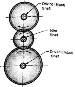
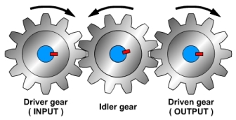
2. Simple gear train with idler:
- In this arrangement, in addition to one gear on driving shaft and one gear on driven shaft; there are one or more than one idler gears placed between driving gear and driven gear.
| |
| |
- When more than two gears are in mesh, the arrangement of gears is called Gear Train.
- All the middle (in-between) gears are called Idle Gears because speed of output (driven) gear does not depend upon size or number of teeth of in-between gears.
- Idle gears only changes the direction of rotation of output (driven) gear, not the speed.
- In simple gear train (when more than 2 gears are in mesh),
- N1 T1 = N2 T2 =N3 T3 = N4 T4 = ------------ = Constant
- N1 D1 = N2 D2 =N3 D3 = N4 D4 = ------------ = Constant
 = --------- = Constant
- The idler gears are used for following purposes:
(a) to have the larger center distance between the driving shalt and the driven shaft.
(b) to have the desired direction of rotation of driven shaft.
Speed Ratio (Gear Ratio) of Simple Gear Train:
|
Advantages
- Compact in size.
- Positive drive.
- High Power Transmission capacity.
- Used at high speeds.
- Can be used for different orientations of shaft axes.
- Longer life.
Disadvantages
- Not suitable for longer distances.
- Cost is high
- Problem of vibration
- Lubrication needed.
- Affected by dust and dirt.
- Precise alignment needed.
Comparison between Belt, Chain & Gear Drive
Sr. No. | Parameter | Belt Drive | Chain Drive | Gear Drive |
1 | Type of Drive | Non Positive (Slip is Present) | Positive (No slip) | Positive (No slip) |
2 | Elements of Drive | Belt, Driving & Driven Pulley | Chain, Driving & Driven Sprocket. | Gear & Pinion |
3 | Centre Distances | Used for Long Centre Distances | Used for medium Centre Distances | Used for short Centre Distances |
4 | Suitability for high Speed | Not Suitable | Suitable for moderate speeds only | Suitable |
5 | Lubrication | Not Required | Periodically Required | Continuously Required |
6 | Power Transmission | Low | Moderate | High |
7 | Space Requirement | More | Medium | Less |
8 | Position of Axes of two shaft | Parallel | Parallel | Parallel, Perpendicular, Intersecting & Non-Intersecting |
9 | Operation | Noisy Operation | Smooth & Quite Operation. |
|
10 | Cost | Cheaper. | Costlier than belt drive | Highly expensive |
11 | Ability to absorb shocks | Flexible. Hence it can absorb shocks | Can absorb shocks | Cannot absorb shocks |
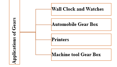
APPLICATIONS OF GEARS
|
Construction:
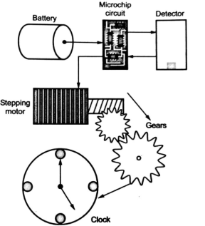
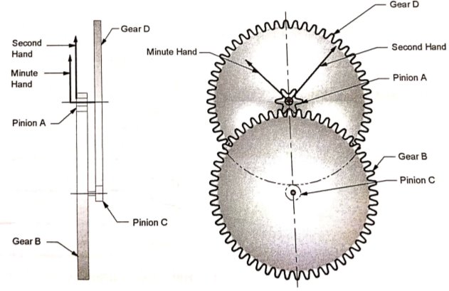
- Basic components of the wall clock are electric stepping motor, battery, microchip, quartz crystal oscillator, gears used to turn hour, minute and second hands at different speeds, shaft to hold the hands in place etc.
|
Figure: Basic Components of wall clock
|
Figure: Wall Clock Mechanism
Working:
- In wall clocks we have a particular arrangement of the gears which are used to move hour, minute and second hand in various ratio by using the battery source.
- As shown in the Figure the battery sends an electrical signal to the quartz crystal when oscillates at a precise frequency.
- The circuit counts the numbers of vibrations and used them to generate electric pulses.
- These pulses are given to the stepping motor which drives the gear wheel that spins the clock's second, minute and hour hand.
A spring is defined as an elastic or resilient body, whosefunction is to deflect or deform (change in shape and size – generally elongation or compression) when load is applied and recover its original shape when load is removed.
Applications of springs:
1) To apply a force, e.g. springs in clutches, brakes, spring loaded valves, etc.
2) To measure a force, e.g. spring balance.
3) To store an energy, e.g. springs in clocks, toys etc.
4) To absorb shocks and vibrations, e.g. springs in vehicle suspension system
Types of springs:
1) Helical Compression and Tension Springs
2) Conical and Volute Springs
3) Torsion Springs
4) Spiral Springs
5) Disc or Belleville Springs
6) Leaf or Laminated Springs
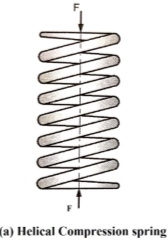
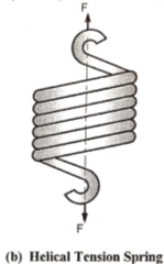
- Helical Compression and Tension Springs
- Helical springs are made of wire wound in the form of helix. Wire cross-section is circular.
|
|
Figure: Helical Compression Spring & Helical Tension Spring
- Helical springs are used in door lock, clutch, shock absorber.
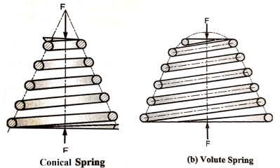
2. Conical and Volute Springs
- In conical and volute springs, as the load increases the number of active coils gradually decreases. The decreasing number of coils results in an increasing spring stiffness.
|
Figure: Conical and Volute Spring
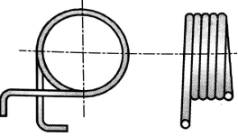
3. Torsion Springs
- Torsion springs are of helical or spiral type. These springs are used to apply the small torque.
|
Figure: Torsion Spring
The helical torsion springs are used in door-hinges and automobile starters.
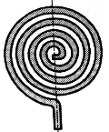
4. Spiral Springs
|
Figure: Spiral Spring
- Used in watches and clocks.
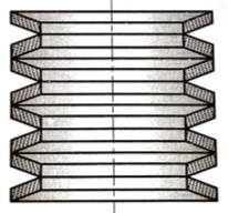
5. Disc or Belleville Springs:
- Disc or Belleville springs are made up of number of conical discs held together by a central bolt or a pipe passing through disc hole.
|
Figure: Disc or Belleville Spring
- These springs are used where high spring stiffness is required.
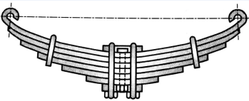
6. Leaf or Laminated Springs:
- Leaf spring consists of a number of leaves held together by means of clamps and bolts.
|
Figure: Leaf Spring
- Application of leaf spring: It is commonly used in automobile suspension system.
APPLICATIONS OF SPRING
1) Door Closure
2) Door Lock
3) Shock Absorber
4) Clutches
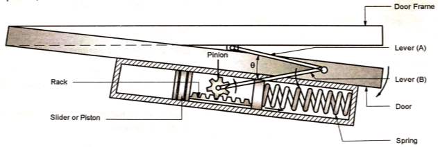
- In door closure mechanism, energy applied by the person to open the door is stored in the helical compression spring. When the door is released, the energy is utilized to restore or bring the door to original position (i.e. closed position)
- The lever A is connected to door frame while lever B is connected to the pinion of the door closure mechanism mounted on the door. The two levers are connected to each other through the pin joint.
- When the person applies the force on the door to open it, the angle θ between two levers increases.
|
Figure: Door Closure Mechanism
- Due to this, the lever B rotates in anticlockwise direction. As Lever B is connected to pinion, pinion also rotates in anticlockwise direction. The pinion is in mesh with rack. Hence, rack moves, towards right side.
- Because of motion of rack towards right side, the helical spring get compressed and energy is stored in the helical compression spring.
- When person releases the door, the spring extends and restores to original length. The spring applies restoring force on rack and pushes rack towards left-side.
- Because of linear motion of rack in towards left, the pinion rotates in clockwise direction. The angle θ between two levers reduces and door is closed.
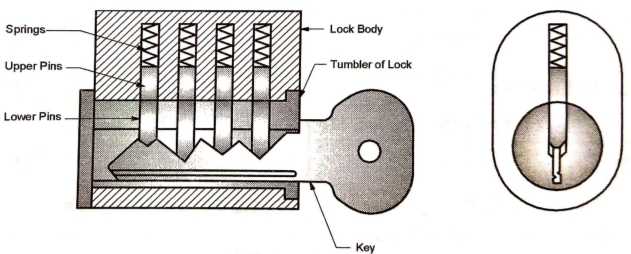
- The main components of door lock are series of lower pins of different lengths. The profile of lower side of lower pins match with the profile of the key, as shown in Fig.
- These are series of upper pins and helical compression springs.
|
Figure: Door Lock
- The varying lengths of lower pins and profile of key give the level of security to lock.
- To open the lock, the tumbler should rotate. When correct key is inserted, the profile of the key perfectly adjust the heights of lower pins such that the top surfaces of lower pins matches with the tumbler surface and tumbler can rotate with the lower pins and key.
- In locked position, as correct key is not in place, the lower pins as well as upper pins are pushed downward. Hence, upper pins lock tumbler with the body of the lock.
- The helical compression springs exert the force on the pins and ensure that the pins can be moved up only when key is inserted.
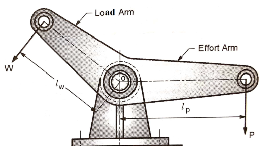
- Lever is a rigid rod or bar pivoted at a point called fulcrum and used: (i) to overcome load by application of small effort, or (ii) to facilitate application of effort in desired direction.
|
Figure: Lever
- Effort arm and load arm: In a lever, a perpendicular distances of the effort and load from the fulcrum are known as effort arm and load arm respectively.
- Leverage and mechanical advantage: The ratio of the effort arm to the load arm is called leverage. The ratio of load to the effort is called as mechanical advantage.
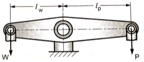
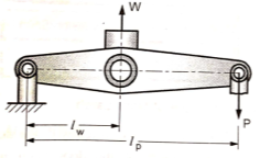
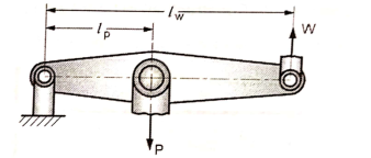
- Let ,
- W = Load to be overcomed, N
- P= effort applied, N
- lw= load arm, mm
- lp= effort arm, mm
Taking moment about fulcrum,


Types of Levers
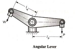
- Angular Lever
- The lever in which load arm and effort arm are inclined at an angle other than 180° are known as angular levers.
|
- Such levers are used to facilitate the application of effort in the desired direction. Generally, the angle between the two arms is 135° in angular levers.
- Examples: Rocker arms in I.C. engines and brake levers.
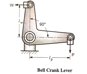
2. Bell Crank Lever
- When the angle between the load arm and effort arm is 90°, the lever is known as bell crank lever.
|
- Examples: Levers in governor and levers in railway signals.
3. One Arm Lever
- The one arm lever which has only one arm and that is effort arm. This type of lever is used to apply external torque.
|
- The examples of such type of lever are: hand levers, foot levers, cranking levers, etc.
- Examples of hand levers: Hand brake in car, levers in lathe, milling machine, etc.
- Examples of foot levers: Brake lever in car, kick start in two wheelers, etc.
4. Lever with Fulcrum between Load and Effort
|
- In Such levers, generally Mechanical advantage is greater than one.
- Examples: Handle of hand pump, Rocker arm in IC engine, Beam of balance etc.
5. Lever with Load Between Fulcrum and Effort
|
- In Such levers, generally Mechanical advantage is greater than one because the effort arm is greater than load arm.
- Examples: Lever of boiler safety valve.
6. Lever with Effort Between Load and Fulcrum
|
- In Such levers, generally Mechanical advantage is LESS than one because the effort arm is smaller than load arm.
- Examples: Forceps
APPLICATIONS OF LEVERS
1) Door Latch
2) Brake Lever
3) Clutch Lever
4) Hand Pump
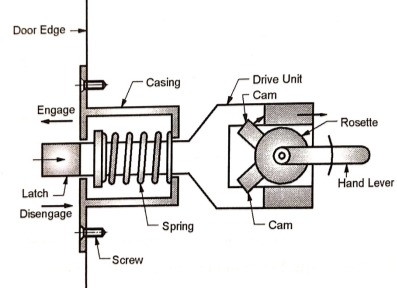
- Door latch is a mechanism fitted with the door. When door is closed, latch of the door latch mechanism engages with the strike plate fitted on the door frame.
- Once closed, the door cannot be opened unless the latch is disengaged from strike plate by using hand lever.
- In order to open the door hand lever is rotated in clockwise direction (or anticlockwise direction).
|
Figure: Door Latch
- The hand lever is a one arm lever and it is used to apply the torque.
- The hand lever is fitted on the rosette and cam is connected to rosette.
- As hand lever rotates the cam applies the force on drive unit and pulls drive unit toward right by overcoming the spring force.
- As the latch is connected to the drive unit, it is retracted from the strike plate and door is disengaged.
- When hand lever is releases, the restoring force of the spring forces the drive unit as well as the latch to move towards the left.
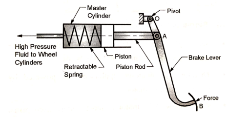
- The brake lever (pedal) is used for applying the brake in vehicles.
- The brake lever (pedal) is pivoted at point 0. It is connected to piston rod at point A and braking force is applied at point B.
- When braking force is applied at point B, the piston rod pushes the piston and increases the pressure of brake fluid in master cylinder.
- The high pressure brake fluid is supplied to all wheel cylinders for braking action.
|
Figure: Brake Pedal
- When brake is released, the retractable spring helps to bring the piston and brake lever to original position.
- Valve is mechanical device which controls or regulates the flow of fluid (gas, liquid or slurry) by opening or closing.
- Applications of Valves:Valves are used for starting, stopping or controlling the flow of: (i) Water (water tap) (ii) Gas (iii) Slurry (iv) Oil (v) Steam
- Types of Valves:
- Gate valve
- Ball Valve
- Globe Valve
- Butterfly Valve
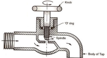
- Water tap is used to start, stop or control the flow of water. When knob is rotated, the spindle moves up and down.
|
- The upward movement of spindle opens the passage of water flow while downward movement of spindle closes the passage of water flow.
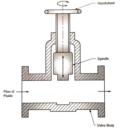
- Fig. shows a gate valve. By rotating the hand wheel, the spindle can be moved up and down.
|
- The upward movement of the spindle can open the passage of fluid flow, while the downward movement of the spindle can close the passage of fluid flow.
- Prime mover is a machine that converts energy from an energy source into shaft power (mechanical energy).
- The various prime movers are electric motor, I.C. engine, and Turbines.
- Electric motor is a prime mover that converts an electric energy into shaft power (mechanical energy).
- Electric energy is common source of energy easily available. Hence, electric motor is most popular and commonly used prime mover for domestic applications well as industrial applications.
Types of Electrical Motors:
- A.C. Motors
- D.C. Motors
- Single phase A.C. motors
- Single phase A.C. (Alternating Current) supply is readily available in almost all households.
- Therefore, all domestic appliances are powered by single phase A.C. motors.
- Single phase A.C. motor is most widely used prime motor in domestic appliances.
2. Three phase A.C. motors:
- Three phase A.C. (Alternating current) supply is available in all industrial units (large, medium or small).
- Hence, three phase A.C. motors are widely used as prime movers in industrial applications.
Applications of Electrical Motors in Domestic/Home Appliances
- Fan
- Exhaust Fan
- Water Pump
- Washing Machine
- Water Purifier Unit
- Refrigerator
- Split Air Conditioner
- Water Cooler
- Vacuum Cleaner
- Chimney of kitchen
FAN
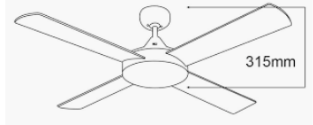
- Fan is a machine used to create a flow of air or gas. The fan has an impeller, which consists of number of blades or vanes mounted on the hub.
- The impeller or assembly of blades is driven by an electric motor. The rotating blades force the air to flow.
|
- The fan can produce an air flow with high volume and low pressure (higher than atmosphere pressure).
- The fans are used for air circulation in houses, offices, halls, industries, etc.
EXHAUST FAN
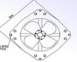
- Exhaust fan is a machine used for pulling air out of place like : kitchen, bathrooms, toilets, etc. It helps to drive out unwanted smoke, fumes, odor, and moisture out of the particular room or area.
- The exhaust fan has an impeller, which consists of number of blades or vanes mounted on hub. The impeller is driven by on electric motor.
|
- The fan creates air flow while exhaust fan pulls air out. The function of exhaust fan is exactly reverse as that of fan.
- A pump is a machine that transfers energy to a fluid so as to lift the fluid to a higher level, to transport the fluid from one place to another, to pressurize the liquid for sonic useful purpose or to circulate the liquid in a piping system.
- It converts input mechanical energy given by electrical motor or engine into Hydraulic Energy (Pressure energy and or Kinetic energy) of the fluid.
Types of Pumps
- Positive displacement pumps (ex. Reciprocating Pump)
- Rotodynamic Pump (Centrifugal Pump)
CENTRIFUGAL PUMP
Principle
- The Centrifugal Pump works on the principle of conversion of the rotational kinetic energy into an increased fluid pressure. Centrifugal Pumps are used for large discharge through smaller heads.
Construction and Working:
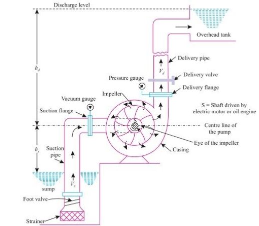
- Figure shows the schematic diagram of a centrifugal pump. It consists of an impeller enclosed in a volute casing.
- The impeller is coupled with prime movers such as internal combustion engine or electric motor, which makes the impeller to rotate inside the volute casing.
- The rotation of the impeller imparts kinetic energy to the fluid forcing the fluid to move outward from the impeller vanes to the periphery.
- At the periphery, the change in area of the volute casing converts the fluid kinetic energy (velocity) into (static) pressure head.
Efficiency of Pump
Q = Volume flow rate of liquid, m3/s ρ = Density of liquid, Kg/ m3 H = Height through which liquid is lifted P= Power of Centrifugal pump, Watt Pi= Input Power of motor, Watt
|
Specifications of Pump:
Power | 5 HP |
Speed | 300 rpm |
Phase | 3 |
Voltage | 440 V |
Head | 20 m |
Discharge | 8.5 Lps |
Outlet Pipe | 50 mm |
Inlet Pipe | 65 mm |
Water Pump-Set for Overhead Tanks
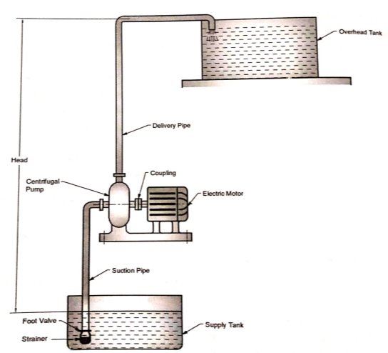
The water pump-set consists of centrifugal pump coupled to an electric motor.
|
Figure: Water Pump-Set for Overhead Tanks
- The suction pipe is connected to an eye of the impeller and the delivery pipe is connected to the output of the pump.
- The water is lifted form the supply tank to the overhead tank. The height though which the water is lifted is called the head of the pump.
RECIPROCATING PUMP
|
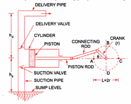
Fig: Layout of a Reciprocating Pump
Construction and Working:
- The working of the reciprocating pump is very simple and just like an I.C engine. First of all the piston has the function of providing the suction force, so that the liquid can be lift up or can be sucked in with great force.
- After that comes the compression part which will impart the required pressure energy to the fluids. In this part of the phase the piston have to do a great work so that the liquid can be compressed properly and its pressure can increased to the desired level.
- The inlet and the outlet valve open at a certain pressure which is set by the manufacturer.
- If the piston is of single acting type which means it can suck from one side and transmit to the same side only.
- But we can have the double reciprocating pump too which have the function of the giving suction and discharge simultaneously in each stroke.
- This pump can be used as the compressor also but for that we have to have a good valve arrangement which can operate with good frequency.
Advantages of Reciprocating pump
- Gives high pressure at outlet.
- Gives high suction lift.
- Priming is not required in this pump.
- They are used for air also.
Disadvantages of Reciprocating pump
- High wear and tear, so requires lot maintenance.
- The flow is not uniform, so we have to fit a bottle at both ends.
- The flow is very less and cannot be used for high flow operations.
- More heavy and bulky in shape.
- Initial cost is much more in this pump.
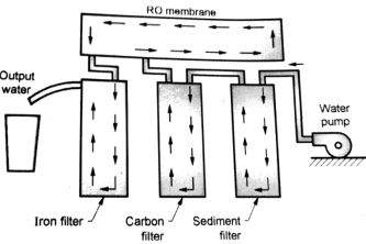
- Water filter purifier unit consists of four major components.
1. Sediment filters 2. Carbon filters 3. Iron filter 4. RO membrane.
- Water from the overhead tank is firstly passed through sediment filter which removes the slits or dirt particles and other large particulate matter.
- This sediment filter needs to be maintained after a periodic time because the particulate matters may clog it in over a period of a time.
- Once it gets clog it needs to be replaced with new one.
- Then water is passed through the carbon filter block which helps to remove chlorine, organics and the chloramines.
|
- If cloramines are present during RO process then it may damage the RO membrane.
- After carbon filter water is passed through RO membrane. RO membrane removes the majority of the impurities from the supplied water. Impurities such as bacteria, heavy metals, salts and other organics.
- After this process water is supplied to the last filter of the system which is iron filter. In this kind of filter deionization takes place.
- A cartridge of negatively and positively charged resins removes the any leftover contaminates including Silicas and phosphate. After this we get pure water which is free from all the impurities.
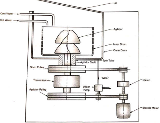
Components of washing machine
- Agitator: The large plastic agitator is mounted on agitator shaft, which is driven by an electric motor through the belt drive.
- Inner Drum:The inner drum is mounted on spin tube, which is again driven by an electric motor through the belt drive. The inner drum is having holes along the surface to throw water out during the spin cycle.
- Outer Drum: The outer drum is stationary and collects the water during spin cycle.
- Electric Motor and Belt Drive:The electric motor drives agitator, inner drum and water pump through the belt drive.
- Clutch: The clutch is mounted between two driving pulleys on the motor shaft.
- Transmission: It is gearbox mounted between belt drive and the agitator shaft.
- Water Pump: The water pump drains the water from the outer drum at the end of spin cycle.
|
Working of Washing Machine:
- The lid is lifted and cloths are dropped from top into the inner drum. The detergent is added. The hot and for cold water enter the drum through the pipes. The lid is then closed.
- During washing cycle, the clutch is disengaged so that the electric motor drives the agitator through the belt drive and transmission. During washing cycle, both the drums remain stationary.
- During spin cycle, the clutch is engaged so that the inner drum starts rotating. The inner drum is mounted on spin tube. The inner drum is driven by an electric motor through the clutch, belt drive and spin tube. During spin cycle, the inner drum throws the water through holes into outer drum.
- The pump drains the water form outer drum.
- An air compressor is a device which compresses the atmospheric air to a higher pressure at the expense of external work supplied either by electric motor or I.C. engine. The compressed air is delivered to a vessel, called receiver, for storage.
- Pressure ratio: It is defined as the ratio of outlet (discharge) pressure to inlet (suction)
Pressure.
RECIPROCATING AIR COMPRESSOR:
Construction:
|
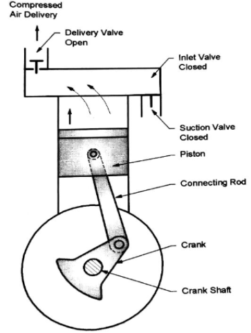
- Reciprocating air compressor consists of a piston which reciprocates in a cylinder. The piston is driven through the connecting rod and the crank. The crankshaft is driven by an electric motor.
- The suction or inlet valve and the delivery valve are mounted in the cylinder head. The valves are automatically opened and closed depending upon the pressure difference across the valves.
Working:
(1) Suction stroke:
- When the piston is moving downwards the delivery valve is closed.
- When the pressure inside the cylinder falls below, the atmospheric pressure, the inlet valve opens. The atmospheric air is sucked inside the cylinder up to the end of suction stroke.
(2) Compression and delivery stroke:
- When the piston is moving upwards, the air inside the cylinder is compressed
- When the pressure inside the cylinder reaches above the pressure on delivery side (i.e. receiver pressure), the delivery valve opens. The compressed air from the cylinder is discharged to the receiver.
Applications of Compressed Air:
- To operate pneumatic tools like: drill, hammers, riveting machine, etc.
- For spray painting
- In refrigeration and air conditioning industry
- For conveying the materials like sand Concrete along a pipe line
Specifications of Compressor:
Freezer Capacity | 60 Liter |
Food Capacity | 178 Liter |
Voltage | 220-240 V |
Current Rating | 0.8 A |
Frequency | 50 Hz |
Number of Doors | 2 |
Refrigerant | R 134a |
Defrost System | Auto Defrost |
REFRIGERATOR
- Refrigerator is an appliance having thermally insulated compartment from which the heat is removed artificially and is maintained at lower temperature for storage of food.
- The capacity of refrigerator is the volume of inside storage space of the refrigerator. It is expressed in litre (165 litre, 190 litre, 265 litre etc.)
|
Construction and Working:
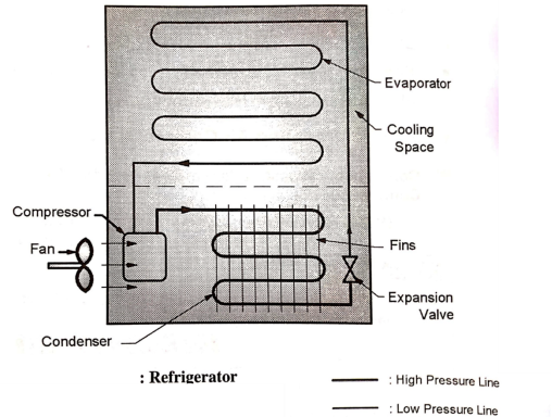
- Compressor:The low pressure and temperature refrigerant in vapor state enters the compressor.
In compressor, the low pressure and low temperature refrigerant in vapor state is compressed to high pressure and temperature.
- Condenser:The high pressure and temperature refrigerant in vapour state enters the condenser from compressor where it rejects the heat to surrounding atmosphere.
The condenser coils are provided with fins for effective heat dissipation.
- Expansion Valve:In expression valve, the expansion of refrigerant takes place. The pressure as well as temperature of refrigerant is reduced.
The liquid refrigerant at low pressure and temperature again enters the evaporator.
- Evaporator:Evaporator is a coil placed around the cooling space of the refrigerator. The low temperature and low pressure refrigerant in liquid state passes through the evaporator coil.
It absorbs the heat from the space to be cooled and converts the liquid refrigerant into vapour state. The heat absorption takes place at constant pressure and temperature.
- Refrigerant used in refrigerator are R134a, R12 etc.
Coefficient of Performance (COP):
|
Air Conditioner:
- Air conditioner is a system that removes heat and moisture from the enclosed space to improve the comfort of occupants.
Split Air Conditioner:
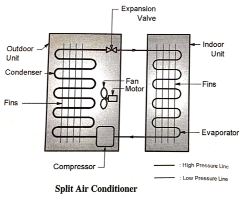
- The split air conditioner is an air conditioner with two separate units: indoor unit and outdoor unit.
- The indoor unit is installed inside the room to be air conditioned and outdoor unit is installed on the exterior wall or outside the room to be air conditioned.
Construction and Working:
- Compressor: The low pressure and temperature refrigerant in vapour state enters the compressor where it is compressed to high pressure and temperature.
The compressor is placed inside the outdoor unit of split air conditioner.
- Condenser: The high pressure and temperature refrigerant in vapour state enters the condenser when it rejects the heat to surrounding atmosphere.
The condenser coils are provided with fins for effective heat dissipation. The condenser is placed inside the outdoor unit of the split air conditioner.
|
- Expansion valve:In expansion valve, the expansion of refrigerant takes place. The pressure as well as temperature of refrigerant is reduced.
The liquid refrigerant at low pressure and temperature again enters the evaporator coil.
- Evaporator:
Evaporator is a coil placed inside the indoor unit. The low temperature and low pressure refrigerant in liquid state passes through the evaporator coil.
It absorbs heat from the space to be cooled and converts the liquid refrigerant into vapour state. The heat absorption takes place at constant pressure and temperature. The evaporator coils are provided with fins for effective heat absorption.
Specifications of Split Air Conditioner:
Type | Split |
Capacity | 2 Ton |
Cooling Capacity | 6200 W |
Voltage | 230 V |
Electric Consumption | 1290 Units/year |
Refrigerant | R 410a |
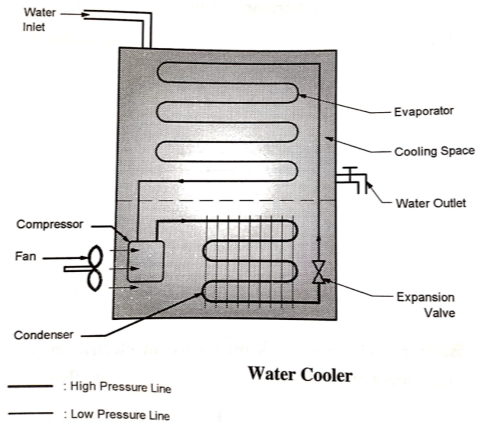
The water cooler is used for cooling the water by removing the heat using refrigeration cycle used in refrigerator.
Construction and Working:
- Compressor: The low pressure and temperature refrigerant in vapour state enters the compressor where it is compressed to high pressure and temperature.
The compressor is placed inside the outdoor unit of split air conditioner.
- Condenser: The high pressure and temperature refrigerant in vapour state enters the condenser when it rejects the heat to surrounding atmosphere.
The condenser coils are provided with fins for effective heat dissipation.
The condenser is placed inside the outdoor unit of the split air conditioner.
|
- Expansion valve:In expansion valve, the expansion of refrigerant takes place. The pressure as well as temperature of refrigerant is reduced. The liquid refrigerant at low pressure and temperature again enters the evaporator coil.
- Water Tank: Stores water.
The compressors, blowers and fans all increase the pressure of gas or air. All three i.e. compressors, blowers and fans are driven by electric motor.
Construction and Working:
- Fan:Fan is a machine used for moving the large amount of air or gas with low increase in pressure. In case of fans, the ratio of discharge pressure to suction pressure is up to 1.11.
- Blower:Blower is a machine used for moving or blowing the air or gas with moderate increase in pressure. In case of blowers, the ratio of discharge pressure to suction pressure is between 1.11 to 1.2.
- Compressor: Compressor is a machine used for increasing the pressure of air or gas by reducing the volume. In case of compressor, the ratio of discharge pressure to suction pressure is above 1.2.
Principle
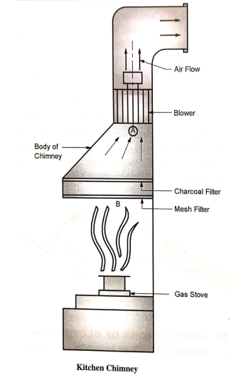
- When pressure difference is created between two locations, air flows from the location of high pressure to the location of lower pressure. The kitchen chimney sucks the smoke, fumes and air inside the kitchen and keeps kitchen fresh and odor free.
|
Construction and Working:
- Blower: The blower is driven by an electric motor. The direction of blower is kept such that air flows in upward direction as shown in Fig. 46. It creates vacuums (negative pressure) at point A and sucks fumes and air form kitchen.
- Mesh (Cassette) Filter:The Mesh filter has multiple layers of mesh, made of aluminum or stainless steel. It retains oil particles and smoke particles.
- Charcoal Filter:Charcoal filter absorbs the remaining oil particles and releases relatively clean air for passing it through the chimney to the outside atmosphere.
- Body of Chimney: The body of chimney provides passage to smoke and air from kitchen to the outside atmosphere.
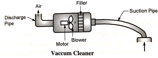
Vacuum cleaner is an apparatus which collects dust and small particle form floors, other surfaces and appliances by means of suction.
Construction and Working:
|
- Motor and Centrifugal Blower:When pressure difference is created between two locations, Particles or material flows from the location of high pressure to the location of low pressure.
The centrifugal blower creates vacuum (negative pressure) at point A.
- Filter:Because of vacuum at Point A the dust and small material particles are sucked in through the suction pipe.
The filter removes the dust and small material particles and clean air is discharged to the atmosphere.
- Suction Pipe:The dust and other small material particles are sucked through the suction pipe.
- Discharge Pipe:The discharge pipe discharges clean air to the atmosphere.
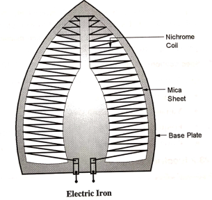
Principle:
When electric current is passed through coil, it gets heated.
Construction and Working:
- Nichrome coil:In electric iron, the Nichrome coil is used as a heating element. It has relatively high resistance. Therefore, when current is passed through the Nichrome coil, it produces high heat.
- Mica Sheets:The Nichrome coil is placed between two mica sheets. The Mica is an electric insulator but a good conductor of heat.
|
- Steel Base Plate and Body:When an electric current is passed through the heating coil (Nichrome coil); the coil gets heated. The heat is transferred to base plate due to conduction.
- The heat of base plates and manual pressure applied on iron, helps to iron the clothes.
Heat generated by Coil:

Where,
H = Heat generated, Jules (J)
I = Electric current through coil, A
R = Resistance of coil, ohm
V = Voltage
t = Time, Sec
Principle
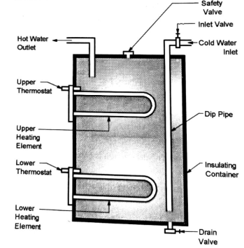
In electric geyser, the current is passed through the heating coil. The coil gets heated. The heat of coil is used for raising the temperature of water through conduction.
Construction and Working:
- Insulating Container: The container is provided with insulating layer so as to avoid the dissipation of heat to surrounding atmosphere.
- Cold Water Inlet and Dip Pipe:The cold water is supplied to the geyser through cold water inlet pipe.The cold water inlet pipe is provided with inlet valve so as to control the supply of cold water. The cold water to geyser is supplied in the lower part of the tank through dip pipe.
|
- Hot water Outlet:The hot water is taken out from the geyser through the hot water outlet. The hot water is light, and hence, it is in the upper part of tank.
- Upper Heating Element and Thermostat: The upper heating element has a heating coil. First the upper heating element functions until the upper tank is hot. The upper heating element has its own thermostat. Once the upper tank is hot, thermostat cut-offs electric supply to the upper heating element.
- Lower Heating Element and Thermostat:Once the upper heating element is cut-off, the lower heating element starts functioning. It has its own thermostat. Both the heating elements do not function simultaneously.
- Safety valve:If the pressure inside the geyser shoots up because of some reason, the safety valve opens and releases the high pressure fluid to ensure the safety.
Heat generated by Heating Element or Coil:

Where,
H = Heat generated, Joule
I = Electric current through Heating Element or coil, A
R = Resistance of Heating Element or coil, ohm
V = Voltage
T = Time, Sec
Heat given to water

Where,
H = Heat given to water, Joule
m = Mass of water, Kg
Cp = Specific Heat of water J/kgºC
ΔT = Temperature rise of water, ºC
Specifications of Electric Geyser:
Tank Capacity | 15 Liter |
Voltage | 220-240 V |
Frequency | 50 Hz |
Power | 2000 W |
Standing loss | 0.45 kWh/24 hours |
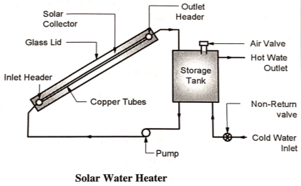
Solar water heater is used to heat water by using solar energy which is renewable, non-polluting and available free of cost in abundance.
|
Construction and Working:
- Storage Tank: The cold water is supplied to the storage tank form inlet pipe. The non-return valve fitted on the inlet pipe prevents the reverse flow of water from storage tank to the inlet pipe.
- Pump:The supply tank supplying the water to storage tank should be at sufficient height. If there is no sufficient gravity head, the pump is used to supply the water to the solar collector from storage tank.
- Solar Collector:The solar collector consists of an insulated box covered with glass lid. The insulated box contains number of copper tubes, connected between inlet header and outlet header. The copper tubes are painted by black color form outside.
- The cold water enters the inlet header and flow through the copper tubes. The solar radiation heats the water flowing through the copper tubes (copper is a good conductor of heat). The black color is a good absorber of heat.
- The glass lid prevents the loss of heat due to radiation.The solar collector is inclined so that as water gets heated, it moves up. The hot water form outlet header flows to the storage tank.
Reference Books
1. Khan, B. H., “Non Conventional Energy Sources, Tata McGraw-Hill Publisher Co. Ltd.
2. Boyle, Godfrey, “Renewable Energy”,2nd Ed., Oxford University Press
3. Khurmi, R.S. ,and Gupta, J. K.,“A Textbook of Thermal Engineering”, S. Chand & Sons
4. Incropera, F. P. and Dewitt, D.P., (2007), “Fundamentals of Heat and Mass Transfer, 6th Ed., John Wiley and Sons, USA
5. Groover,Mikell P., (1996), “Fundamentals of Modern Manufacturing: Materials, Processes, and Systems”, Prentice Hall, USA
6. Norton, Robert L., (2009), “Kinematics and Dynamics of Machinery”, Tata McGrawHill
7. Cleghorn, W. L., (2005), “Mechanisms of Machines”, Oxford University Press
8. Juvinal, R. C., (1994), “Fundamentals of Machine Component Design”, John Wiley and Sons, USA
9. Ganeshan, V., (2018), “Internal Combustion Engines”, McGraw Hill
10. Anderson, Curtis Darrel and Anderson,Judy, (2010), “Electric and Hybrid Cars: A History”, 2nd Ed., McFarland


