Unit 1
Data Communication and Network Models
Data Communications refers to the transfer of data or information between the source and the receiver. Data Communication is the method of transfer and preservation of data during transfer process.
The source transmits the data, and the receiver receives it.
Data communication involves communication networks, different communication services, kind of networks available, protocol architectures, OSI models, TCP/IP protocol models etc.
In Local Area Networks the computers are connected to share resources. Even though the computers have different disk operating systems, languages, cabling and locations, they still communicate to one another and share resources.
The rules and regulations are called protocols and standards in Data Communications.
Source
It is the generator of data that will pass on to the destination using networks. Without any request source it never passes data to destination. So, if source is passing the data means any of the destinations is requesting for data using some query languages.
Transmitter
It is a device used to convert the data as per the destination requirement. For example a modem, converts the analog (telephonic signals) signal to digital (computer signals) signals as well as digital to analog also.
Transmission System
To transmit the data on different connected systems different transmission systems are used. Data transmission using transmission system means the physical transfer of data over point-to-point or point-to-multipoint communication channels.
Example of such channels are copper wires, optical fibres even wireless communication channels etc.
Receiver
The receiver receives the signals from the transmission system and converts it into a form that is suitable to the destination device.
For example, a modem accepts analog signal from a transmission channel and transforms it into digital bit stream which is acceptable by computer system.
Destination
The destination is a device for which source device sends data.
Analog and Digital Signals
Like the data signals can be either analog or digital. An analog signal has infinitely many levels of intensity over a period. As the wave moves from value A to value B, it passes through and includes infinite number of values along its path. A digital signal can have only limited number of defined values. Although each value can be any number, it is often 1 and 0.
The curve representing the analog signal passes through an infinite number of points. The vertical lines of the digital signal, however, demonstrate the sudden jump that the signal makes from value to value.
A/D Signal Conversion Methods
There are several methods for analog to digital conversion. Some of them are:
Flash Conversion
When an ADC (analog to digital converter) has a comparator that fires for each decoded voltage range, it is not a direct conversion ADC or flash ADC. Code is generated for each voltage from the comparator bank to logic circuit for each voltage range.
Direct conversion is fast typically only 8 bits of resolution (256bit comparators) or less. A large expensive circuit is usually needed.
ADCs of this type have a high input capacitance ,large die size, and are prone to produce glitches on the output.
Successive Approximation Conversion
A successive-approximation ADC settles on final voltage range, by using comparator to reject ranges of voltages.
Successive approximation operates by comparing the input voltage constantly to a known reference voltage until the best approximation is achieved.
At each step in this process, a binary value of the approximation is stored in a successive approximation register (SAR).
A reference voltage is used for the SAR. If the input voltage is 150V and the reference voltage is 100V, then in the 1st clock cycle the voltage out is negative (because 100V is less than 150V). The voltage might increase by say 30V in the 2nd clock cycle, to 130V. This value still a negative value. The 3rd clock cycle results in 160V. Because of this, the output exceeds the input voltage and is positive. The binary form 110 is the result.
When the number of bit cycles is increased and the increment rise decreases, it is possible to construct an accurate A/D converter.
Delta-Encoded Conversion
A delta-encoded ADC consists of up-down counter. This counter feeds a digital to analog converter (DAC). The input signal and the DAC both go to a comparator. The comparator controls the counter.
The comparator uses negative feedback from the circuit to adjust the counter until the DAC's output is close to the input signal. The number is read from the counter.
Delta converters have wide ranges, as well as high resolution, but the conversion time depends on the input signal level.
D/A signal conversion methods
There are many methods that exist for Digital to Analog (D/A) converters.
There are 4 basic methods described below:
Using Resistors
Resistance elements are the most easy-to-use analog elements in LSI(Large Scale Integration).Relative accuracy is comparatively good, making it possible to achieve 10-bit precision without trimming.
Selecting the appropriate resistance makes it possible to cover a wide range, from low to high speeds.
Using Capacitors
Usage of capacitance results in better accuracy than resistance, therefore it more preferred method for medium and high precision D/A converters.
However, high accuracy requires a large capacitance which leads to longer charge/discharge times. Also, high-speed operation is problematic.
To compensate for leakage current at low frequencies refresh is required which complicates operation.
Using Current
This is adopted in conversion systems for high-speed (several MHz) applications. Output current switching is performed by switching the current source based on digital input. Resistors and operational amplifier are utilized to convert the output current to voltage.
Oversampling Method
This conversion method is used for high accuracy (16bit~) applications. This method filters low-resolution, high sampling rate to obtain the desired analog signal. Generally, a one- bit digital sigma system consists of a low pass filter and binary output (0, 1).
A/A Signal Conversion methods
Analog-to-Analog Conversion
Analog signals are modified to represent analog data. This conversion is also known as Analog Modulation. Analog modulation is required when bandpass is used. Analog to analog conversion can be done in three ways:
- Amplitude Modulation
In this modulation, the amplitude of the carrier signal is modified to reflect the analog data.
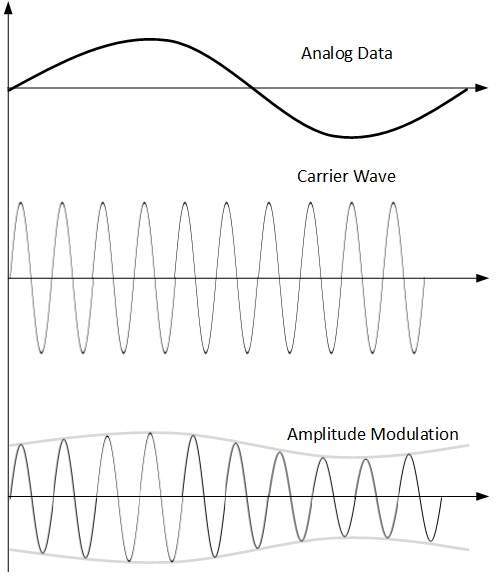
The amplitude of modulating signal (analog data) is multiplied by the amplitude of carrier frequency, which then reflects analog data.
The frequency and phase of carrier signal remain unchanged.
- Frequency Modulation
In this modulation technique, the frequency of the carrier signal is modified to reflect the change in the voltage levels of the modulating signal (analog data).
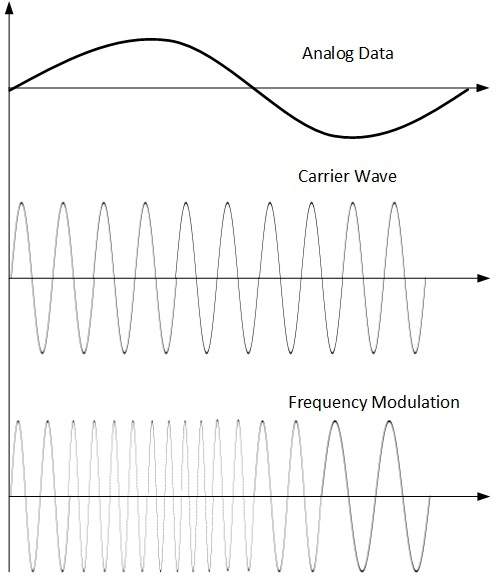
The amplitude and phase of the carrier signal are not altered.
- Phase Modulation
In this modulation technique, the phase of carrier signal is modulated to reflect the change in voltage (amplitude) of analog data signal.
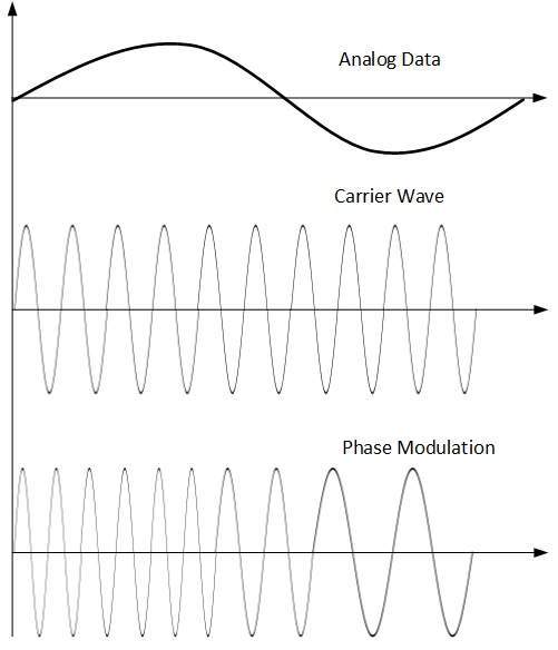
Phase modulation is similar to Frequency Modulation, but in Phase modulation frequency of the carrier signal is not increased. Frequency of carrier is signal is changed (made dense and sparse) to reflect voltage change in the amplitude of modulating signal.
Digital to Digital Conversion
Digital to digital conversion can be done in two ways, line coding and block coding. For all communications, line coding is necessary whereas block coding is optional.
Line Coding
The process for converting digital data into digital signal is said to be Line Coding. Digital data is found in binary format. It ‘s represented (stored) internally as series of 1s and 0s.
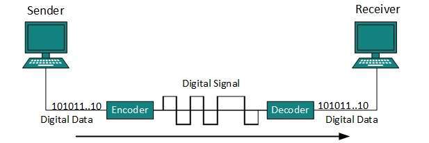
Digital signal is denoted by discrete signal, which represents digital data.
There are three types of line coding schemes available:

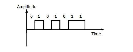
Uni-polar Encoding
Unipolar encoding schemes use single voltage level to represent data. To represent binary 1, high voltage is transmitted and to represent 0, no voltage is transmitted. It is also called Unipolar-Non-return-to-zero, because there is no rest condition that is it either represents 1 or 0.
Polar Encoding
Polar encoding scheme uses multiple voltage levels to represent binary values. Polar encodings are of four types:
- Polar Non-Return to Zero (Polar NRZ)
It uses two different voltage levels to represent binary values. Generally, positive voltage represents 1 and negative value represents 0. It is also NRZ because there is no rest condition.
NRZ scheme has two variants: NRZ-L and NRZ-I.
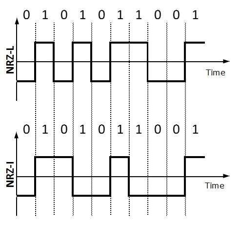
NRZ-L changes voltage level at when a different bit is encountered whereas NRZ-I changes voltage when a 1 is encountered.
Return to Zero (RZ)
Problem with NRZ is that the receiver cannot conclude when a bit is ended and when the next bit is started that is when sender and receiver’s clock are not synchronized.
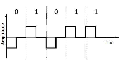
RZ uses three voltage levels, positive voltage to represent 1, negative voltage to represent 0 and zero voltage for none. Signals change during bits not between bits.
Manchester
This encoding scheme is a combination of RZ and NRZ-L. Bit time is divided into two halves. It transits in the middle of the bit and changes phase when a different bit is encountered.
Differential Manchester
This encoding scheme is a combination of RZ and NRZ-I. It also transmits at the middle of the bit but changes phase only when 1 is encountered.
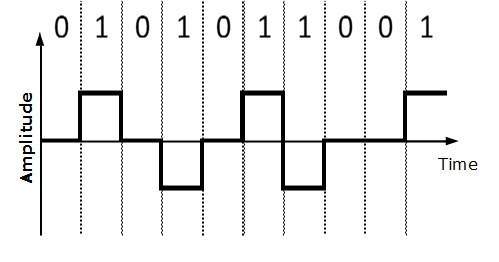
Bipolar Encoding
Bipolar encoding uses three voltage levels, positive, negative and zero. Zero voltage represents binary 0 and bit 1 is represented by altering positive and negative voltages.
Block Coding
To obtain accuracy of the received data frame redundant bits are used. For example, in even-parity, one parity bit is added to make the count of 1s in the frame even. In this way the original number of bits is increased. It is called Block Coding.
Block coding is represented by slash notation, mB/nB.Means, m-bit block is substituted with n-bit block where n > m.
Block coding involves three steps:
- Division,
- Substitution
- Combination.
After block coding is done, it is line coded for transmission.
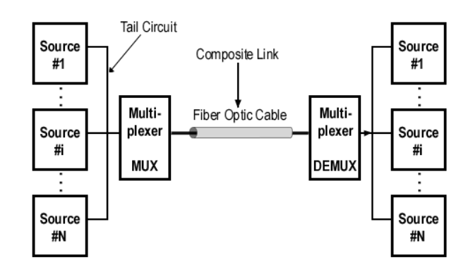
Bandwidth utilization is the use of available bandwidth to achieve specific goals. Efficiency is achieved by multiplexing, privacy and antijamming which can be achieved by using spreading.
Multiplexing is a set of techniques that allows simultaneous transmission of multiple signals across single data link. In this system n lines share bandwidth of one link, link refers to physical path and channel refers to the portion of the link that carries transmission.
There are basically three multiplexing techniques:
Frequency division multiplexing
Wave- length division multiplexing
Time division multiplexing.
The first two are designed for analog signals and the third for digital signals.
An important consideration in data communication is how fast we send data in bits per second over the channel. Data rate depends on three factors
- Bandwidth available
- Level of signals we use
- The quality of the channel.
Multiplexing is a technique in which different analog and digital streams of transmission are simultaneously processed over a shared link.
Multiplexing divides the high capacity medium into low capacity logical medium which is shared by different streams.
Communication is possible over the air (radio frequency), using a physical media (cable), and light (optical fibre). All mediums are capable of multiplexing.
When multiple senders try to send over a single medium, a device called Multiplexer divides the physical channel and allocates one to each. On the other end of communication, a De-multiplexer receives data from a single medium, identifies each, and sends to different receivers.
The different multiplexing techniques are:
Frequency Division Multiplexing
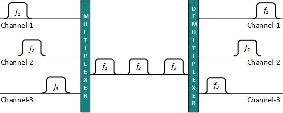
FDM is an analog technology when the carrier is frequency. FDM divides the spectrum or carrier bandwidth in logical channels and allocates one user to each channel.
Each user can use the channel frequency independently and has exclusive access of it.
All channels are divided in such a way that they do not overlap with each other. Channels are separated by guard bands. Guard band is a frequency which is not used by either channel.
Time Division Multiplexing
TDM is applied primarily on digital signals but can be applied on analog signals as well. In TDM the shared channel is divided among its user by means of time slot.
Each user can transmit data within the provided time slot only. Digital signals are divided into frames which is equivalent to time slot that is a frame of an optimal size which can be transmitted in given time slot.
TDM works in synchronized mode. Both ends that is Multiplexer and De-multiplexer are timely synchronized and both switch to next channel simultaneously.
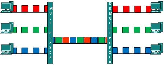
When channel A transmits its frame from one end, the De-multiplexer provides media to channel A on the other end. As soon as the channel A’s time slot expires, this side switches to channel B.
The De-multiplexer works in a synchronized manner and provides media to channel B. Signals from different channels travel the path in interleaved manner.
Wavelength Division Multiplexing
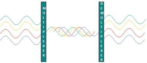
Light has different wavelength (colors). In fiber optic mode, multiple optical carrier signals are multiplexed into an optical fiber by using different wavelengths. This is analog multiplexing technique and works in the same manner as FDM but uses light as signals.
Code Division Multiplexing
Multiple data signals are transmitted over a single frequency by using Code Division Multiplexing. FDM divides the frequency in smaller channels but CDM allows its users to full bandwidth and transmit signals all the time using a unique code. CDM uses orthogonal codes to spread signals.
Each station is assigned with a unique code, called chip. Signals travel with these codes independently, inside the whole bandwidth. The receiver knows in advance the chip code signal it can receive.
Data rate refers to the speed of data transfer through a channel. It is generally computed in bits per second (bps).
Higher data rates are expressed as Kbps ("Kilo" bits per second, i.e.1000 bps), Mbps ("Mega" bits per second, i.e.1000 Kbps), Gbps ("Giga" bits per second, i.e. 1000 Mbps) and Tbps ("Tera" bits per second, i.e. 1000 Gbps).
There are three factors that determine the data rate of a channel:
- Bandwidth of the channel
- Number of levels of signals that are used
- Noise present in the channel
Data rate is calculated using the formulae:
Nyquist bit rate- for noiseless channel
Shannon’s capacity – for noisy channel.
Nyquist Bit Rate
Nyquist bit rate developed by Henry Nyquist proved that the transmission capacity has maximum limit when an even perfect channel has no noise.
The theoretical formula for the maximum bit rate is:
Maximum bit rate = 2 × Bandwidth × log2V
Here, maximum bit rate is calculated in bps
Bandwidth is the bandwidth of the channel
V is the number of discrete levels in the signal
For example, if there is a noiseless channel with a bandwidth of 4 KHz that is transmitting a signal with 4 discrete levels, then the maximum bit rate will be computed as, maximum bit rate = 2 × 4000 × log24 = 16,000 bps = 16 kbps
Shannon's Capacity
Claude Shannon extended Nyquist's work for actual channels subject to noise. Noise are of various types like thermal noise, impulse noise, cross-talks etc. Among this thermal noise is unavoidable.
The random movement of electrons in the channel creates an extraneous signal which is not present in the original signal, called the thermal noise. The amount of thermal noise is calculated as the ratio of the signal power to noise power, SNR.
Signal-to-Noise Ratio,SNR = Average Signal Power/Average Noise Power
SNR is the ratio of two powers that varies over large range which is expressed in decibels called SNRdb = 10log10SNR.
Shannon's Capacity gives the theoretical maximum data rate or capacity of a noisy channel. It is expressed as:
Capacity = Bandwidth × log2( 1+SNR )
Here, Capacity is the maximum data rate of the channel in bps
Bandwidth is the bandwidth of the channel
SNR is the signal – to – noise ratio
For example, if the bandwidth of a noisy channel is 4 KHz, and the signal to noise ratio is 100, then the maximum bit rate can be computed as:
Capacity = 4000 × log2( 1+100 ) = 26,633 bps = 26.63 kbps
Topology defines the structure of the where all the components are interconnected to each other.
There are two types of topology: physical and logical topology.
Physical topology refers to the geometric representation of all the nodes in a network.
A logical topology refers to a concept in networking that defines the architecture of the communication mechanism for all nodes in a network.
Bus Topology
In Bus topology, all devices share single communication line or cable. There may arise a problem while multiple hosts are sending data at the same time.
Therefore, it uses CSMA/CD technology or recognizes one host as Bus Master to solve the issue.
It is one of the simplest forms of networking where the failure of a device does not affect the other devices. However, failure of the shared communication line can make all other devices stop functioning.
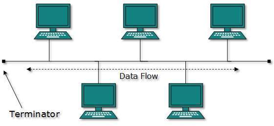
Both ends of the shared channel have line terminator. The data is sent in only one direction and as soon as it reaches the extreme end, the terminator removes the data from the line.
Star Topology
All hosts in Star topology are connected to a central device known as hub device using a point-to-point connection. Hence, there exists a point to point connection between hosts and hub. The hub device can be any of the following:
- Layer-1 device such as hub or repeater
- Layer-2 device such as switch or bridge
- Layer-3 device such as router or gateway
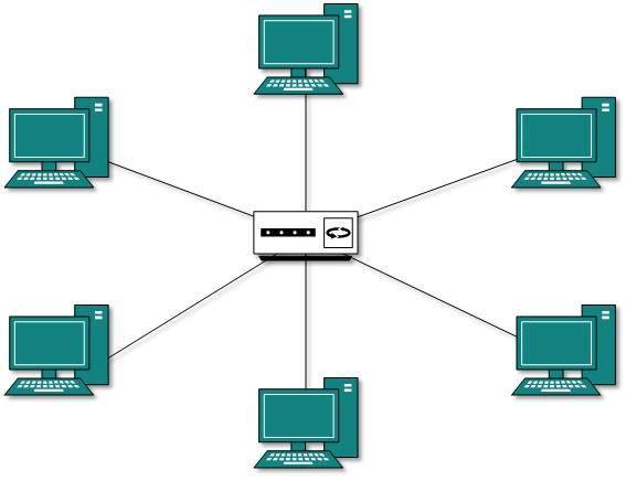
As in Bus topology, hub acts as single point of failure. If hub fails, connectivity of all hosts to all other hosts fails. Every communication between hosts takes place through the hub.
Ring Topology
In ring topology, each host machine connects to exactly two other machines thereby creating a circular network structure. When one host tries to communicate or send message to a host which is not adjacent to it, the data travels through all intermediate hosts. To connect one more host in the existing structure, the administrator may need only one more extra cable.
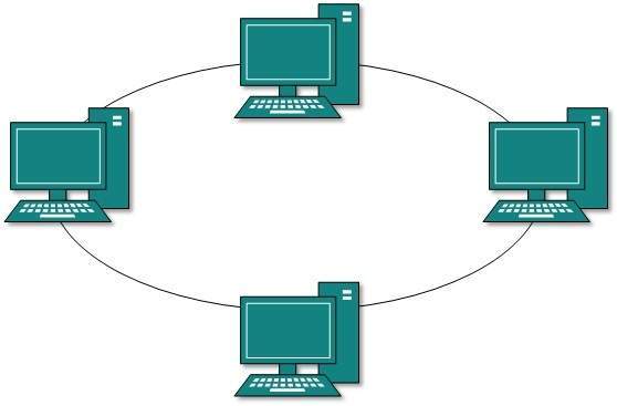
Failure of any host results in failure of the whole ring. Thus, every connection in the ring is a point of failure. There are methods which employ one more backup ring.
Mesh Topology
In this type of topology, a host is connected to one or multiple hosts. This topology has hosts in point-to-point connection with every other host or may also have hosts which are in point-to-point connection to few hosts.
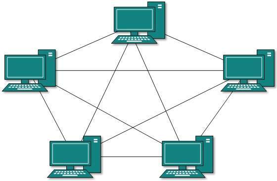
Mesh technology comes into two types:
- Full Mesh: All hosts have point-to-point connection to every other host in the network. Thus, for every new host n(n-1)/2 connections are required. It provides the most reliable network structure among all network topologies.
- Partially Mesh: Not all hosts have point-to-point connection to every other host. Hosts connect to each other in some arbitrarily fashion. This topology is required to provide reliability to some other hosts out of all.
Tree Topology
This topology divides the network in to multiple levels/layers of network. Mainly in LANs, a network is bifurcated into three types of network devices.
The lowermost is access-layer where computers are attached.
The middle layer is known as distribution layer, which works as mediator between upper layer and lower layer.
The highest layer is known as core layer which is central point of the network that is root of the tree from which all nodes fork.
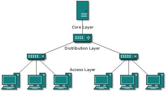
All neighbouring hosts have point-to-point connection between them. Similar, to Bus topology, if the root goes down, then the entire network suffers though it is not the single point of failure.
Daisy Chain
This topology connects all the hosts in a linear fashion. Similar to Ring topology, all hosts are connected to two hosts only, except the end hosts which means, if the end hosts in daisy chain are connected then it represents Ring topology.

Each link in daisy chain topology represents a single point of failure. Every link failure splits the network into two segments. Every intermediate host works as relay for its immediate hosts.
Hybrid Topology
A network structure whose design contains more than one topology is said to be hybrid topology.
Hybrid topology inherits merits and demerits of all the incorporating topologies.
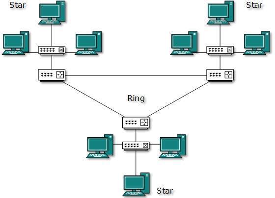
The above picture represents an arbitrarily hybrid topology. The combining topologies may contain attributes of Star, Ring, Bus, and Daisy-chain topologies. Internet is the best example of largest Hybrid topology
In any communication system, during the transmission of the signal, or while receiving the signal, some unwanted signal gets introduced into the communication making it unpleasant for the receiver regarding the quality of the communication. Such a disturbance is called as Noise.
Electrical noise is defined as undesirable electrical energy that falls within the passband of the signal. A noise signal consists of a mixture of frequencies with random amplitudes.
The most prevalent and most interfering to data communication signals are man-made, Thermal noise, correlated noise, and impulse noise.
Man-made noise: Kind of noise produced by mankind. The main sources are spark producing mechanisms like commutators in electric motors, automobile ignition systems, ac power-generating and switching equipment, and fluorescent lights.
It is impulsive in nature and contains a wide range of frequencies propagated in the free space like the radio waves. Man-made noise is most intense in more densely populated areas and sometimes is referred to as industrial noise.
Thermal noise: This is the noise generated by thermal agitation of electrons in a conductor. It is also referred to as white noise because of its uniform distribution across the entire electromagnetic frequency spectrum.
Noise power density is the thermal noise power present in a 1-Hz bandwidth and is given by No = KT.
Thermal noise is independent of frequency and thus thermal noise present in any bandwidth is where N is thermal noise power in watts, K is Boltzmann's constant in joules per Kelvin, T is the conductor temperature in kelvin (0K = -273o C), and B is the bandwidth in hertz. Noise power is often measured in dBm.
The noise power in a resistor at room temperature is:
NdBm = -174 dBm + 10 log B
Correlated noise: This noise is correlated to the signal and cannot be present in a circuit unless there is a signal. Correlated noise is produced by nonlinear amplification and includes harmonic distortion and intermodulation distortion. Harmonic distortion occurs when unwanted harmonics of a signal are produced through nonlinear amplification and is also 28 N = KTB Data C
Impulse noise: This noise is characterized by high-amplitude peaks of short duration in the total noise spectrum. It consists of sudden bursts of irregularly shaped pulses that generally last between a few microseconds and several milliseconds, depending on their amplitude and origin.
Signal-to-noise power ratio:
Signal-to-noise ratio is defined as the power ratio between signal and the background noise where P is average power in watts.
The ratio often expressed in decibels as
S/N (dBm) = 10 log(PS/PN)
In information theory it gives us theoretical maximum bit-rate that can be transmitted with an arbitrarily small bit-error rate (BER), with a given average signal power, over a channel with bandwidth B Hz which is affected by AWGN.
By “arbitrarily small BER” means that provided the conditions of the theorem are met, for any given BER, however small, we can find a coding technique that achieves this BER; the smaller the given BER, the more complicated will be the technique.
The maximum achievable bit-rate (with arbitrary BER) is referred to as the channel capacity C.
The Shannon-Hartley Theorem (or Law) states that:
C = B log 2( 1+S/N) bits/second
Where S/N is the mean square signal to noise ratio (not in dB) and the logarithm is to the base2.
The communication between A and B is a consequence of a physical act performed by A to induce the desired state. This transfer of information is subjected to noise.
The communication is successful if transmitter A and the receiver B agree on what was sent.
The channel capacity is defined as the logarithm of the number of distinguishable signals that can be sent through the channel. Source symbols from some finite alphabet are mapped into some sequence of channel symbols which produces the output sequence of the channel. The output sequence is random but has distribution that depends on the input sequence.
Each of the possible input sequences induces probability distribution on the output sequences.
We can transmit a message with a very low probability of error and reconstruct the source message at the output. The maximum rate at which this can be done is called the capacity of the channel.

The Nyquist theorem shows how to sample a signal or waveform in such a way that we do not lose information.
Suppose that we have a bandlimited signal X(t).
Bandlimited means that if we were to take the Fourier transform of this signal, Xˆ(f) = F{X(t)}, there would be a certain fmax for which,
|Xˆ(f)| = 0 ∀ |f| > fmax,---------------------------------------------- (1)
So that there is no power in the signal beyond the maximum frequency fmax.
The Nyquist theorem states that if we were to sample this signal we would need samples with a frequency larger than twice the maximum frequency contained in the signal, that is
Fsample ≥ 2fmax -------------------------------------------(2)
If this is the case, we have not lost any information during the sampling process and we could theoretically reconstruct the original signal from the sampled signal.
We can define a Nyquist frequency based on a certain sampling frequency: fNyquist = 1 /2 fsample. --------------------------(3)
Any signals that contain frequencies higher than this Nyquist frequency cannot be perfectly reconstructed from the sampled signal, hence called undersampled.
If our signal only contains frequencies smaller than the Nyquist frequency, we can perfectly reconstruct the original signal given the sampled signal, and we are oversampled.
When our signal is bandlimited to a frequency equal to the Nyquist frequency, we are critically sampled. It is sometimes useful to state the Nyquist theorem in a different way.
Suppose we have a certain bandlimited signal with a maximum frequency fmax. The period of this maximum frequency is ∆tmin = 1/fmax.
If we want to correctly sample this signal, we need to sample with a period of ∆t sample ≤ 1 2∆tmin.----------------------------------- (4)
If we were to sample our signal slower, with a longer interval between samples, we would be under sampling our signal.
It is measured at the receiver's front end. To increase the information rate, the signal-to-noise ratio and the allocated bandwidth are tradedagainst each other. For no noise, the signal to noise ratio becomes infinite and so an infinite information rate is possible at small bandwidth.
OSI Model
The data/message flows 2 ways in the OSI model, DOWN (data encapsulation) and UP (data decapsulation).
The figure is an example of a simple data transfer between 2 computers and shows how data is encapsulated and decapsulated:
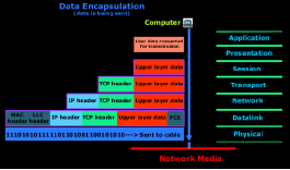
The computer from the figure needs to send some data to another computer.
The Application layer is where the user interface exists, here the user interacts with the application he or she is using, then this data is passed to the Presentation layer and then to the Session layer.
These three layers add some extra information to the original data that came from the user and then passes it to the Transport layer.
Here the data is broken into smaller pieces (one piece at a time transmitted) and the TCP header is added. At this point, the data at the Transport layer is called a segment.
Each segment is sequenced so the data stream can be put back together on the receiving side exactly as transmitted.
Each segment is then handed to the Network layer for network addressing (logical addressing) and routing through the internet network.
At the Network layer, we call the data which includes at this point the transport header and the upper layer information a packet.
The Network layer add its IP header and then sends it off to the Datalink layer.
Here we call the data which includes the Network layer header, Transport layer header and upper layer information a frame.
The Datalink layer is responsible for taking packets from the Network layer and placing them on the network medium (cable). The Datalink layer encapsulates each packet in a frame which contains the hardware address (MAC) of the source and destination computer (host) and the LLC information which identifies to which protocol in the previous layer (Network layer) the packet should be passed when it arrives to its destination.
At the end the FCS field which is the Frame Check Sequence is used for error checking and is also added at the end by the Datalink layer.
If the destination computer is on a remote network, then the frame is sent to the router or gateway to be routed to the desination. To put this frame on the network, it must be put into a digital signal.
Since a frame is really a logical group of 1's and 0's, the Physical layer is responsible for encapsulating these digits into a digital signal which is read by devices on the same local network.
There are also a few 1's and 0's put at the beginning of the frame so the receiving end can synchronize with the digital signal it will be receiving.
The figure shows what happens when the data is received at the destination computer.
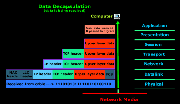
The receiving computer will first synchronize with the digital signal by reading the few extra 1's and 0's. Once the synchronization is complete and it receives the whole frame and passes it to the layer above it which is the Datalink layer.
The Datalink layer will do a Cyclic Redundancy Check (CRC) on the frame. This is a computation which the computer does and if the result it gets matches the value in the FCS field, then it assumes that the frame has been received without any errors. Next the Datalink layer will strip off any information or header which was put on by the remote system's Datalink layer and pass the rest .
At the Network layer the IP address is checked and if it matches (with the machine's own IP address) then the Network layer header, or IP header if you like, is stripped off from the packet and the rest is passed to the above layer which is the Transport layer. Here the rest of the data is now called a segment.
The segment is processed at the Transport layer, which rebuilds the data stream and acknowledges to the transmitting computer that it received each piece.
Since we are sending an ACK back to the sender from this layer that we are using TCP and not UDP. After this it hands the data stream to the upper-layer application.
OSI model addressing mechanism:
- The Network layer of the OSI model is responsible for managing logical addressing information in the packets and the delivery of those packets to the correct destination.
- Routers, which are special computers used to build the network, direct the data packet generated by Network Layer using information stored in a table known as routing table.
- The routing table is a list of available destinations that are stored in memory on the routers. The network layer is responsible for working with logical address.
- The logical address are used to uniquely identify a computer on the network, but at the same time identify the network that system resides on.
- The logical address is used by network layer protocols to deliver the packets to the correct network. The logical addressing system used in Network Layer is known as IP address.
Devices
Layer 1 and 2 runs on each internet device, from end-system to router. They are needed to communicate with peers; without the device would be sitting isolated in the network.
Switches are the boxes, that run only layer 1 and 2.
Layer 3 runs on all end systems and on so-called routers. These are devices that either receive IP packets or forward IP packets from one subnetwork to another one.
Layers 4 and above we find on end-systems (clients, servers, etc). The Layer 4 software is responsible for the end-to-end control of the communication flow between two systems.
Data format in TCP/IP suite
TCP is a connection-oriented Layer 4 protocol that provides full-duplex, acknowledged, and flow-controlled service to upper-layer protocols.
It moves data in a continuous, unstructured byte stream. Sequence numbers identify bytes within that stream.
Packet format :
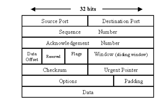
The TCP packet format consists of these fields:
- Source Port and Destination Port fields (16 bits each) identify the end points of the connection.
- Sequence Number field (32 bits) specifies the number assigned to the first byte of data in the current message. Under certain circumstances, it can also be used to identify an initial sequence number to be used in the upcoming transmission.
- Acknowledgement Number field (32 bits) contains the value of the next sequence number that the sender of the segment is expecting to receive, if the ACK control bit is set.
- Data Offset (a.k.a. Header Length) field (variable length) tells how many 32-bit words are contained in the TCP header. This information is needed because the Options field has variable length, so the header length is variable too.
- Reserved field (6 bits) must be zero. This is for future use.
- Flags field (6 bits) contains the various flags:
URG—Indicates that some urgent data has been placed.
ACK—Indicates that acknowledgement number is valid.
PSH—Indicates that data should be passed to the application as soon as possible.
RST—Resets the connection.
SYN—Synchronizes sequence numbers to initiate a connection.
FIN—Means that the sender of the flag has finished sending data. - Window field (16 bits) specifies the size of the sender's receive window (that is, buffer space available for incoming data).
- Checksum field (16 bits) indicates whether the header was damaged in transit.
- Urgent pointer field (16 bits) points to the first urgent data byte in the packet.
- Options field (variable length) specifies various TCP options.
- Data field (variable length) contains upper-layer information.
TCP packets
TCP almost always operates in full-duplex mode (two independent byte streams traveling in opposite directions). Only during the start and end of a connection will data be transferred in one direction and not the other. TCP uses segments to determine whether the receiving host is ready to receive the data.
When the sending TCP host wants to establish connections, it sends a segment called a SYN to the peer TCP protocol running on the receiving host. The receiving TCP returns a segment called an ACK to acknowledge the successful receipt of the segment. The sending TCP sends another ACK segment and then proceeds to send the data. This exchange of control information is referred to as a three-way handshake.
IP packet format:
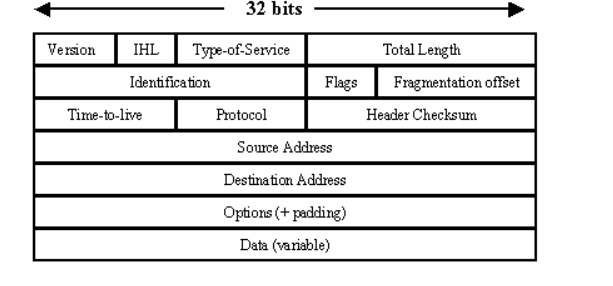
The IP packet format consists of these fields:
- Version field (4 bits) indicates the version of IP currently used.
- IP Header Length (IHL) field (4 bits) indicates how many 32-bit words are in the IP header.
- Type-of-service field (8 bits) specifies how a particular upper-layer protocol would like the current datagram to be handled. Datagrams can be assigned various levels of importance through this field.
- Total Length field (16 bits) specifies the length of the entire IP packet, including data and header, in bytes.
- Identification field (16 bits) contains an integer that identifies the current datagram. This field is used to help reconstruct datagram fragments.
- Flags field (4 bits; one is not used) controls whether routers are allowed to fragment a packet and indicates the parts of a packet to the receiver.
- Time-to-live field (8 bits) maintains a counter that gradually decrements to zero, at which point the datagram is discarded. This keeps packets from looping endlessly.
- Protocol field (8 bits) indicates which upper-layer protocol receives incoming packets after IP processing is complete.
- Header Checksum field (16 bits) helps ensure IP header integrity.
- Source Address field (32 bits) specifies the sending node.
- Destination Address field (32 bits) specifies the receiving node.
- Options field (32 bits) allows IP to support various options, such as security.
- Data field (32 bits) contains upper-layer information.
IP packets (datagrams)
IP attaches an IP header to the segment or packet’s header in addition to the information added by TCP or UDP. Information in the IP header includes the IP addresses of the sending and receiving hosts, datagram length, and datagram sequence order. This is provided in case the datagram exceeds the allowable byte size for network packets and must be fragmented.
Addressing Mechanism in TCP/IP
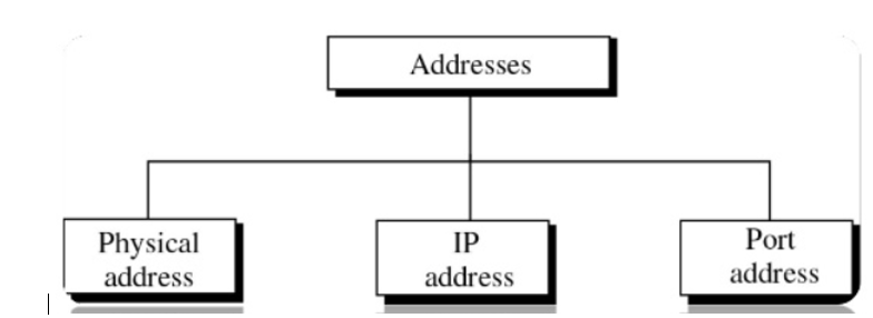
There are four type of addresses used in internet employing the TCP/IP protocols:
- Physical address
- Logical address
- Port address
- Application specific address
Physical Addresses
- The physical address also known as link address is the address of a node defined by its LAN or WAN.
- It is included in the frame used by data link layer. It is the lowest level address.
- The physical addresses have authority over link (LAN or WAN). The size and format addresses vary depending on the network.
- For example, Ethernet uses 60byte physical address. Physical address can be unicast, multicast or broadcast.
Logical address:
- Logical addresses are used by networking software to allow packets to be independent of the physical connection of the network that is to work with different network topologies and types of media.
- A logical address in the Internet is currently 32-bit address that can uniquely define a host connected to the Internet. An internet address in IPv4 in decimal numbers. 132.24.75.9
- No two publicly addressed and visible hosts on the Internet can have the same IP address.
- The physical addresses will change from hop to hop but the logical addresses remain the same.
Port Addresses:
There are many applications running on the computer. Each application run with port no on the computer.
A port number are used with TCP/IP connections.
These port numbers allow different applications on the same computer to share the network resources simultaneously.
The physical addresses change from hop to hop but the logical and port addresses remain the same.
Devices used in each layer of TCP/IP model
1. Physical Layer – Physical layer of TCP/IP model is responsible for physical connectivity of two devices. Some of the devices used in Physical layers are,
- Hubs:
Hubs are devices commonly used to connect segments of a LAN. It contains multiple input/output ports. When signal is at any input port, this signal will be made at all output ports except the one it is coming from. - Cables:
In Wired network architecture (e.g Ethernet), cables are used to interconnect the devices. Some of the types of cables are coaxial cable, optical fiber cable, and twisted pair cable. - Repeaters:
Repeaters are used in transmission systems to regenerate analog or digital signals distorted by transmission loss. Analog repeaters can only amplify the signal whereas a digital repeater can reproduce a signal to near its original quality.
2. Data Link Layer – Data Link layer is responsible to transfer data hop by hop based on the MAC address. Some of the devices used in Data Link layer are,
- Bridges:
A bridge is a type of computer network device that provides interconnection with other networks that use the same protocol, connecting two different networks together and providing communication between them. - Modem:
Modem stands for MOdulator/DEModulator. A modem converts digital signals generated by the computer into analog signals which, then can be transmitted over cable line and transforms incoming analog signals into digital equivalents. - Network Interface Card:
Network interface card is an electronic device that is mounted on ROM of the com that connects a computer to a computer network, usually a LAN. It is considered a piece of computer hardware. Most modern computers support an internal network interface controller embedded in the motherboard directly rather than provided as an external component.
3. Network Layer – The network layer is responsible for creating routing table, and based on routing table, forwarding of the input request. Some of the Devices used in Network Layer are,
- Routers:
A router is a switch like device that routes/forwards data packets based on their IP addresses. Routers normally connect Local Area Network (LANs) and Wide Are Network (WANs) together and have a dynamically updating routing table based on which they make decisions on routing the incoming packets. - Brouters:
A bridge router or brouter is a network device that works as a bridge and as a router. The brouter routes packets for known protocols and simply forwards all other packets as a bridge would. Brouters operate at both the network layer for routable protocols (or between network with different data link layer protocol ex. One is running on ethernet (802.3) and other network is running on Token ring (802.5)) and at the data link layer for non-routable protocols (or both network are using same data link layer protocol).
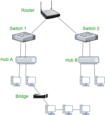
Figure: Typical interconnection of Router, Switch, Hub and Bridge
4. Transport Layer – Transport layer is responsible for end-to-end communication (or process-to-process communication). Some of the transport layer devices are,
- Gateways:
In computer networking, a gateway is a component that is part of two networks, which use different protocols. The gateway is a protocol converter which will translate one protocol into the other. A router is a special case of a gateway. - Firewall:
A firewall is a system designed to prevent unauthorized access to or from a private network, some of the functionalities of firewall are, packet filtering and as a proxy server.
5. Application Layer – Application layer is the top- most layer of TCP/IP Model that provides the interface between the applications and network. Application layer is used exchange messages. Some of the devices used in Application layer are,
- PC’s (Personal Computer), Phones, Servers
- Gateways and Firewalls
To Install and Configure Wired and Wireless NIC and transfer files between systems in LAN and Wireless LAN.
Aim: To Install and Configure Wired and Wireless (remotely) NIC and transfer files between systems in LAN and Wireless LAN between two system in a LAN.
Principle: NICs (Network Interface Card):
Network Interface Card, or NIC is a hardware card installed in a computer so it can communicate on a network. The network adapter provides one or more ports for the network cable to connect to, and it transmits and receives data onto the network cable.
Wireless LAN card: Every networked computer must also have a network adapter driver, which controls the network adapter. Each network adapter driver is configured to run with a certain type of network adapter.
Procedure: (a) Install the network card:
Disconnect all cables connected to the computer and open the case. Locate an available PCI slot (white slots) and insert the network card and secure the card with the screw that came with it. Once the adapter has been installed and secured close the computer case, connect all the cables and turn it on. After installing the adapter driver it should be working find, now let’s configure the card for use on a network.
Click on the Start button and select Settings then Control Panel. Double click on the System icon Click on the Hardware tab. Click on Device Manager. You will see a list of devices installed in your computer.
If necessary, click on the + sign next to Network Adapters to expand the list. Ensure that there is no yellow exclamation mark (!) next to the Network Adapter.
This indicates a possible problem with the card or configuration. Double click on your network driver (e.g. NE2000 Compatible).
In the Device Status box you should see the message:
This Device is working correctly. If you do not see this message or if there is no Network Adapter displayed, then your Ethernet card will probably need configuring.
Result: Installation and configuration of Wired and Wireless (remotely) NIC and transfer files between systems in LAN and Wireless LAN between two systems in a LAN have been done successfully.
To Install and configure Network Devices HUB, Switch and Routers PCs are interfaced using connectivity devices.
Principle:
1. Repeater: Functioning at Physical Layer.A repeater is an electronic device that receives a signal and retransmits it at a higher level and/or higher power, or onto the other side of an obstruction, so that the signal can cover longer distances. Repeater have two ports ,so cannot be use to connect for more than two devices.
2. Hub: An Ethernet hub, active hub, network hub, repeater hub, hub or concentrator is a device for connecting multiple twisted pair or fiber optic Ethernet devices together and making them act as a single network segment. Hubs work at the physical layer (layer 1) of the OSI model. The device is a form of multiport repeater. Repeater hubs also participate in collision detection, forwarding a jam signal to all ports if it detects a collision.
3. Switch:A network switch or switching hub is a computer networking device that connects network segments.The term commonly refers to a network bridge that processes and routes data at the data link layer (layer 2) of the OSI model. Switches that additionally process data at the network layer (layer 3 and above) are often referred to as Layer 3 switches or multilayer switches.
4. Bridge: A network bridge connects multiple network segments at the data link layer (Layer 2) of the OSI model. In Ethernet networks, the term bridge formally means a device that behaves according to the IEEE 802.1D standard. A bridge and switch are very much alike; a switch being a bridge with numerous ports. Switch or Layer 2 switch is often used interchangeably with bridge. Bridges can analyse incoming data packets to determine if the bridge is able to send the given packet to another segment of the network
5. Router: A router is an electronic device that interconnects two or more computer networks, and selectively interchanges packets of data between them. Each data packet contains address information that a router can use to determine if the source and destination are on the same network, or if the data packet must be transferred from one network to another. Where multiple routers are used in a large collection of interconnected networks, the routers exchange information about target system addresses, so that each router can build up a table showing the preferred paths between any two systems on the interconnected networks.
6. Gate Way: In a communications network, a network node equipped for interfacing with another network that uses different protocols.
• A gateway may contain devices such as protocol translators, impedance matching devices, rate converters, fault isolators, or signal translators as necessary to provide system interoperability. It also requires the establishment of mutually acceptable administrative procedures between both networks.
• A protocol translation/mapping gateway interconnects networks with different network protocol technologies by performing the required protocol conversions.
Procedure:
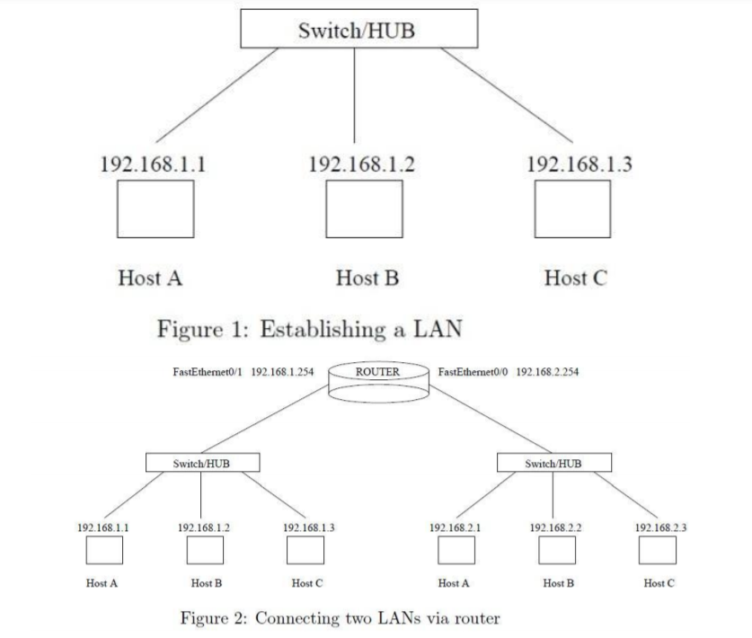
Result: Thus install and configure Network Devices PCs are interfaced using connectivity devices – Hub, router and switch have been done successfully.
References:
Tcp/Ip Protocol Suite Book by Behrouz A. Forouzan
Open Systems Networking: TCP/IP and OSI Book by David M. Piscitello and Lyman Chapin
Patterns in Network Architecture: A Return to Fundamentals Book by John Day