Unit 3
Multiaccess Mechanism and Ethernet Standards
CSMA
Carrier sense multiple access (CSMA) is based on "sense before transmit" principle. CSMA can reduce the possibility of collision but cannot eliminate it. The possibility of collision still exists because of propagation delay, when a station sends a frame other stations still need to sense that. Thus, a station may sense the medium and find it idle because the first bit sent by another station has not been received yet.
For example,
A B C D
T2
T1
At time T1 station A senses the medium and finds it idle, so it sends a frame. At time T2 (T2> T1) station C senses the medium and finds it idle because the first bit from station A has not reached station C yet. Station C also sends a frame. The two signals collide and both frames are destroyed.
Vulnerable Time
The vulnerable time for CSMA is the propagation time Tp. The propagation time is needed for a signal to propagate from one end of the medium to another end. When two stations try to send respective frames simultaneously a collision will result. But if the first bit of the frame reaches the end of the medium, every station should have heard the bit and will refrain from sending them.
Persistence Methods for CSMA
There are basically three persistence methods:
- 1-Persistent
- Non-Persistent
- p-Persistent
1) 1-Persistent
The 1-persistent method is simple and straightforward. When a station finds the channel idle, it sends its frame immediately (with probability 1).
This method has the more chances of collision because two or more stations may find the channel idle at the same time and send their frames immediately.
2) Non-persistent method
In the non-persistent method, a station that has a frame ready to be sent senses the line first. If the channel is idle, it sends immediately. If the channel is not idle, it waits a random amount of time like Aloha and then senses the line again.
The non-persistent method reduces the chance of collision because it is unlikely that two or more stations will wait for the same amount of time since it is random and retry to send simultaneously.
3) p-persistent method
The p-persistent method is used if the channel is slotted in time slots with a slot duration equal to or greater than the maximum propagation time. The p-persistent method reduces the chance of collision and improves efficiency. In this method, after the station finds the channel idle it follows these following steps:
- With probability p, the station sends its frame.
- With probability q = 1 -p, the station waits for the beginning of the next time slot and checks the line again.
- If the line is idle, it goes to step 1.
- If the line is busy, it acts as though a collision has occurred and uses the back-off procedure like Aloha.
CSMA/CD
Carrier Sense Multiple Access with Collision Detection (CSMA/CD) –
In this method, a station monitors the medium after it sends a frame to see if the transmission was successful. If successful, the station is finished, if not, the frame is sent again.
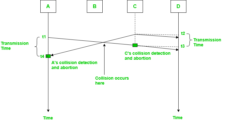
In the diagram, A starts to send the first bit of its frame at t1 and since C sees the channel idle at t2, starts sending its frame at t2. C detects A’s frame at t3 and aborts transmission. A detects C’s frame at t4 and aborts its transmission. Transmission time for C’s frame is therefore t3-t2 and for A’s frame is t4-t1.
Therefore, frame transmission time (Tfr) should be at least twice the maximum propagation time (Tp). This can be deduced when the two stations involved in collision are maximum distance apart.
Process –
The entire process of collision detection is explained as:
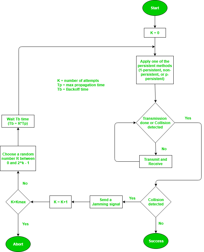
Throughput and Efficiency – The throughput of CSMA/CD is much greater than pure or slotted ALOHA.
- For 1-persistent method throughput is 50% when G=1.
- For non-persistent method throughput can go upto 90%.
CSMA/CA
Carrier Sense Multiple Access with Collision Avoidance (CSMA/CA) –
In CSMA/CA is that the station should be able to receive while transmitting to detect a collision from different stations.
In wired networks, if a collision has occurred then the energy of received signal almost doubles and the station can sense the possibility of collision.
In wireless networks, most of the energy is used for transmission and the energy of received signal increases by only 5-10% if there is collision.
It cannot be used by the station to sense collision. Therefore CSMA/CA has been specially designed for wireless networks.
These are three types of strategies:
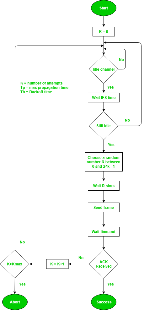
- InterFrame Space (IFS) – When a station finds the channel busy, it waits for a period of time called IFS time. IFS can also be used to define the priority of a station or a frame. Higher the IFS lower is the priority.
- Contention Window – It is the amount of time divided into slots.A station which is ready to send frames chooses random number of slots as wait time.
- Acknowledgements – The positive acknowledgements and time-out timer can help guarantee a successful transmission of the frame.
Process –
The entire process for collision avoidance can be explained as follows:
In controlled access, the stations seek information from one another to find which station has the right to send. Only one node can send at a time, to avoid collision of messages on shared medium.
The three controlled-access methods are:
- Reservation
- Polling
- Token Passing
Reservation
- In the reservation method, a station needs to make a reservation before sending data.
- The time-line has two kinds of periods:
- Reservation interval of fixed time length
- Data transmission period of variable frames.
- If there are M stations, the reservation interval is divided into M slots, and each station has one slot.
- Suppose if station 1 has a frame to send, it transmits 1 bit during the slot 1. No other station can transmit during this slot.
- In general, i th station may announce that it has a frame to send by inserting a 1 bit into i th slot. After all N slots have been checked, each station knows which stations wish to transmit.
- The stations which have reserved their slots transfer their frames in that order.
- After data transmission period, next reservation interval begins.
- Since everyone agrees on who goes next, there will never be any collisions.
The following figure shows a situation with five stations and a five- slot reservation frame.
In the first interval, only stations 1, 3, and 4 have made reservations. In the second interval, only station 1 has made a reservation.

Polling
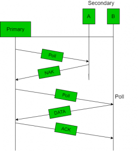
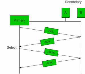
- Polling process similar to roll-call is performed in class. Just like the teacher, a controller sends a message to each node in turn.
- In this, one acts as a primary station(controller) and the others are secondary stations. All data exchanges must be made through the controller.
- The message sent by the controller contains the address of the node being selected for granting access.
- Although all nodes receive the message only the addressed one responds to it and sends data. If there is no data, usually a “poll reject” (NAK) message is sent back.
- Problems include high overhead of the polling messages and high dependence on the reliability of the controller.
Efficiency
Let Tpoll be the time for polling and Tt be the time required for transmission of data. Then,
Efficiency = Tt / (T t + T poll)
Token Passing
- In token passing scheme, the stations are connected logically to each other in form of ring and access of stations is governed by tokens.
- A token is a special bit pattern or a small message, which circulate from one station to the next in some predefined order.
- In Token ring, token is passed from one station to another adjacent station in the ring whereas in Token bus, each station
uses the bus to send the token to the next station in some predefined order. - In both cases, token represents permission to send. If a station has a frame queued for transmission when it receives the token, it can send that frame before it passes the token to the next station. If it has no queued frame, it passes the token simply.
- After sending a frame, each station must wait for all N stations (including itself) to send the token to their neighbours and the other N – 1 stations to send a frame, if they have one.
- Problems like duplication of token or token is lost or insertion of new station, removal of a station, which need be tackled for correct and reliable operation of this scheme.

Performance
Performance of token ring is concluded by 2 parameters: -
- Delay, which is a measure of time between when the packet is ready and when it is delivered. So, the average time (delay) required to send a token to the next station = a/N.
- Throughput, which is a measure of the successful traffic.
Throughput S = 1/(1+a/N) for a<1 and
S= 1/ {a(1+1/N)} for a>1
Where N = number of stations
a = Tp / Tt ; Tp = Propagation delay , Tt = Transmission delay.
Channelization is a multiple-access method in which the bandwidth available of a link is shared in time, frequency, or through code, between different stations.
The three channelization protocols are FDMA, TDMA, and CDMA.
The Frequency-Division Multiple Access (FDMA):
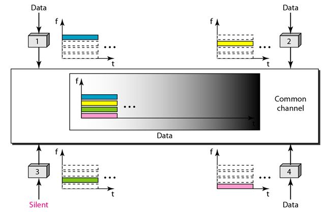
In frequency-division multiple access (FDMA) bandwidth available is divided into frequency bands. Each station is allocated a band to send its data.
Each band is reserved for a specific station and it belongs to the station all the time. Each station uses a bandpass filter to confine the transmitter frequencies.
To prevent station interferences, the allocated bands are separated from one another by small guard bands. The following figure shows the idea of FDMA.
Time-Division Multiple Access (TDMA):
In time-division multiple access (TDMA), the stations share the bandwidth of the channel in time. Each station is allocated a time slot during which it can send data. Each station transmits its data in is assigned time slot. The following figure shows the idea behind TDMA.
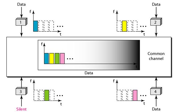
The main problem with TDMA lies in achieving synchronization between the different stations. Each station needs to know the beginning of its slot and the location of its slot. This is difficult because of propagation delays are introduced in the system if the stations are spread over a large area.
Hence to compensate for delays guard times are inserted. Synchronization is normally accomplished by having some synchronization bits at the beginning of each slot.
Code-Division Multiple Access (CDMA):
CDMA means communication with different codes. CDMA differs from FDMA because only one channel occupies the entire bandwidth of the link. It differs from TDMA because all stations can send data simultaneously and there is no timesharing.
Let us assume we have four stations 1, 2, 3, and 4 connected to the same channel. The data from station 1 are d1, from station 2 are d2, and so on. The code assigned to first station is c1, and second is c2, and so on. We assume that the assigned codes have two properties.
1. If we multiply each code by another, we get 0.
2. If we multiply each code by itself, we get 4 that is the number of stations.
With this in picture the four stations can send data using the same common channel, as shown in the following figure.
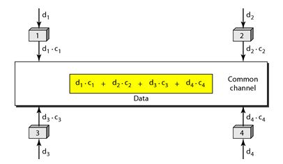
Station 1 multiplies its data by its code to get d1.c1. Station 2 multiplies its data by its code to get d2.c2. And so on. The data that go on the channel are the sum of all these terms, as shown in the box.
Any station that wants to receive data from one of the other three multiplies the data on the channel by the code of the sender.
For example, suppose stations 1 and 2 are talking to each other. Station 2 wants to hear what station 1 is saying. It multiplies the data on the channel by c1 the code of station1.
Because (c1.c1) is 4, but (c2 . c1), (c3. c1), and (c4 .c1) are all 0s, station 2 divides the result by 4 to get the data from station1.
Data =(d1.c1+d2.c2+d3.c3+d4.c4).c1
= c1. d1. c1+ c1. d2. c2+ c1. d3. c3+ c1. d4. c4= 4d1
IEEE 802.3
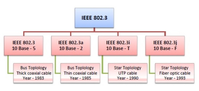
IEEE 802.3 defines the physical layer and medium access control (MAC) sub-layer of the data link layer for wired Ethernet networks.
Ethernet is classified into two categories: classic Ethernet and switched Ethernet.
Classic Ethernet is the original form of Ethernet that provides data rates between 3 to 10 Mbps. The varieties are commonly referred as 10BASE-X.
A switched Ethernet uses switches to connect to the stations in LAN. It replaces the repeaters used in classic Ethernet and allows full bandwidth utilization.
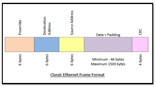
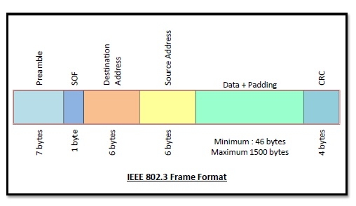
Frame Format of Classic Ethernet and IEEE 802.3
The main fields of a frame of classic Ethernet are -
- Preamble: It is the starting field that provides alert and timing pulse for transmission. In case of classic Ethernet, it is an 8 byte field and in case of IEEE 802.3 it is of 7 bytes.
- Start of Frame Delimiter: It is a 1-byte field in a IEEE 802.3 frame that contains an alternating pattern of ones and zeros ending with two ones.
- Destination Address: It is a 6- byte field containing physical address of destination stations.
- Source Address: It is a 6- byte field containing the physical address of the sending station.
- Length: It a 7 bytes field that stores the number of bytes in the data field.
- Data: This is a variable sized field carries the data from the upper layers. The maximum size of data field is 1500 bytes.
- Padding: This is added to the data to bring its length to the minimum requirement of 46 bytes.
CRC: CRC stands for cyclic redundancy check. It contains the error detection information.
802.4
Token Bus (IEEE 802.4)
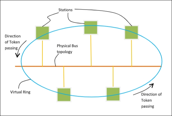
It is a standard for implementing token ring over the virtual ring in LANs. The physical media has a bus or a tree topology and uses coaxial cables. A virtual ring is created with nodes/stations and token is passed from one node to next in a sequence along this virtual ring.
Each node knows the address of its preceding station and its succeeding station. A station can only transmit data when it has the token.
Token Passing Mechanism in Token Bus
A token is a small message that circulates among the stations of a computer network providing permission to the stations for transmission. If a station has data to transmit when it receives a token, it sends the data and then passes the token to the next station or it simply passes the token to the next station.
This is shown in the diagram −
Frame Format of Token Bus
The frame format is given by the following diagram −
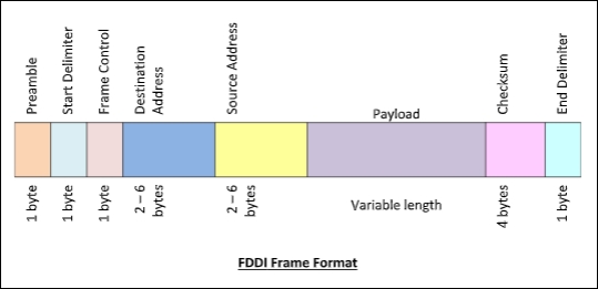
The fields of a token bus frame are −
- Preamble: 1 byte for synchronization.
- Start Delimiter: 1 byte that marks the beginning of the frame.
- Frame Control: 1 byte that specifies whether this is a data frame or control frame.
- Destination Address: 2-6 bytes that specifies address of destination station.
- Source Address: 2-6 bytes that specifies address of source station.
- Payload: A variable length field that carries the data from the network layer.
- Checksum: 4 bytes frame check sequence for error detection.
- End Delimiter: 1 byte that marks the end of the frame.
802.5
IEEE 802.5 Token Ring:
It is a standard for a token-passing ring in Communication networks. A ring consists of a collection of ring interfaces connected by point-to-point lines that is ring interface of one station is connected to the ring interfaces of its left station as well as right station.
These point-to-point links can be created with twisted pair, coaxial cable or fiber optics. Each bit arriving at an interface is copied into a 1-bit buffer. In this buffer the bit is checked and may be modified and is then copied out to the ring again. This copying of bit in the buffer introduces a 1-bit delay at each interface.
Token Ring is a LAN protocol defined in the IEEE 802.5 where all stations are connected in a ring and each station can hear transmissions only from its immediate neighbour.
Permission to transmit is granted by a message (token) that circulates around the ring. A token is a special bit pattern (3 bytes long). There is only one token in the network.
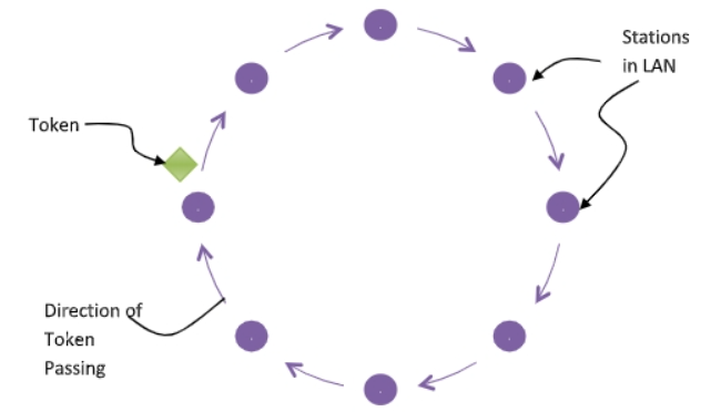
Token-passing networks move a small frame called a token, around the network. If a node receiving the token in order to transmit data, it seizes the token, alters 1 bit of the token appends the information that it wants to transmit, and sends this information to the next station on the ring.
Since only one station can possess the token and transmit data at any given time, there are no collisions. There are two operating modes of ring interfaces. There are listen and transmit.
In listen mode, the input bits are simply copied to output with a delay of 1- bit time. In transmit mode the connection between input and output is broken by the interface so that is can insert its own data.
802.6
IEEE 802.6 standard that is DQDB (Distributed Queue Dual Bus) is a MAN protocol. It can be defined as a high speed shared medium access control protocol that is used over a bus network.
It has two unidirectional buses for controlling purposes where the bus can carry data, video, and voice over a network with bandwidth being allocated as per time slots.
The advantage of using the paired bus is that it is used to tackles failure configuration. It can be extended up to 30 miles at 34-55 Mbps.
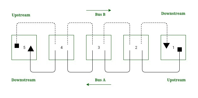
Working of DQDB
Directional Traffic:
Each bus support traffic in only one direction and are opposite to one another. The start of bus is represented as a square and the end of the bus is represented as triangle. Bus A traffic moves from right to left that is from station 1 to 5 whereas the bus B traffic moves from left to right that is from station 5 to 1.
Working:
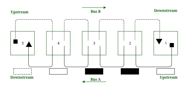
The head of the bus A that is station 1 generates empty slot for use of bus A. Similarly, the head of bus B that is station 5 generate empty slot for use of bus B. The empty slot travels down its bus until the transmission station drops data into it and intended destination reads the data.
Standard Ethernet
In Standard Ethernet, the MAC sublayer governs the operation of the access method. It also frames data received from the upper layer and passes them to the physical layer.
The Ethernet frame contains seven fields:
Preamble, SFD, DA, SA, length, or type of protocol data unit (PDU), upper-layer data, and the CRC.
Ethernet does not provide any mechanism for acknowledging received frames, making it what is known as an unreliable medium.

Each station on an Ethernet network has its own network interface card (NIC). The NIC fits inside the station and provides the station with a 6-byte physical address. The Ethernet address is 6 bytes (48 bits), nominally written in hexadecimal notation, with a colon between the bytes.

Fast Ethernet
The Fast Ethernet standard (IEEE 802.3u) has been established for Ethernet networks that need higher transmission speeds. This standard raises the Ethernet speed limit from 10 Mbps to 100 Mbps with only minimal changes to the existing cable structure. Fast Ethernet provides faster throughput for video, multimedia, graphics, Internet surfing and stronger error detection and correction.
There are three types of Fast Ethernet: 100BASE-TX for use with level 5 UTP cable; 100BASE-FX for use with fiber-optic cable; and 100BASE-T4 which utilizes an extra two wires for use with level 3 UTP cable. The 100BASE-TX standard has become the most popular due to its close compatibility with the 10BASE-T Ethernet standard.
Gigabit Ethernet
Gigabit Ethernet was developed to meet the need for faster communication networks with applications such as multimedia and Voice over IP (VoIP).
GigE is a version of Ethernet that runs at speeds 10 times faster than 100Base-T. It is defined in the IEEE 802.3 standard and is currently used as an enterprise backbone.
From the data link layer of the OSI model upward, the look and implementation of Gigabit Ethernet is identical to that of Ethernet.
The most important differences between Gigabit Ethernet and Fast Ethernet include the additional support of full duplex operation in the MAC layer and the data rates.
Campus network design
Campus network is a building or group of buildings all connected into one enterprise network that consists of many local-area networks (LANs). A campus is generally a portion of a company that is constrained to a fixed geographic area.
The distinct characteristic of a campus environment is that the company that owns the campus network usually owns the physical wires deployed in the campus. The campus network topology is primarily LAN technology connecting all the end systems within the building. Campus networks generally use LAN technologies, such as Ethernet, Token Ring, Fiber Distributed Data Interface (FDDI), Fast Ethernet, Gigabit Ethernet, and Asynchronous Transfer Mode (ATM).
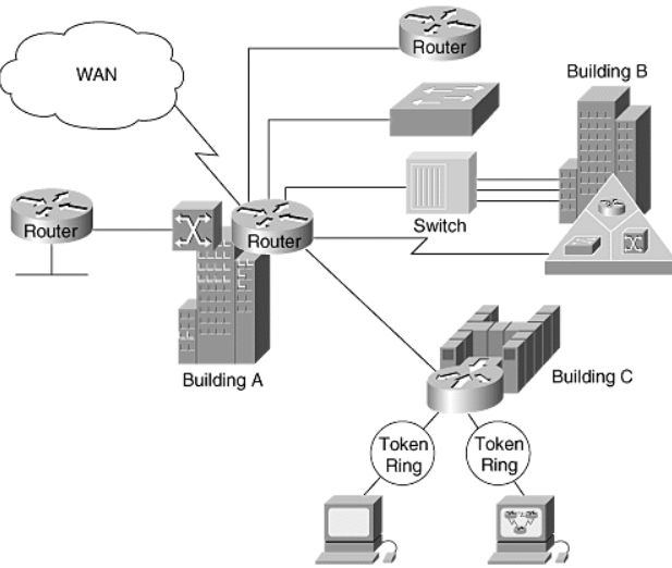
A large campus with groups of buildings can use WAN technology to connect the buildings. Although the wiring and protocols of a campus might be based on WAN technology, they do not share the WAN constraint of the high cost of bandwidth.
After the wire is installed, bandwidth is inexpensive because the company owns the wires and there is no recurring cost to a service provider. Upgrading the physical wiring is xpensive.
Consequently, network designers generally deploy a campus design optimized for the fastest functional architecture that runs on the existing physical wire. They might also upgrade wiring to meet the requirements of emerging applications. For example, higher-speed technologies—such as Fast Ethernet, Gigabit Ethernet, and ATM as a backbone architecture—and Layer 2 switching provide dedicated bandwidth to the desktop.
References:
Tcp/Ip Protocol Suite Book by Behrouz A. Forouzan
Open Systems Networking: TCP/IP and OSI Book by David M. Piscitello and Lyman Chapin
Patterns in Network Architecture: A Return to Fundamentals Book by John Day