Unit 6
Transport Layer – Services and Protocols
- A transport layer protocol provides for logical communication between application processes running on different hosts. Logical communication means that although the communicating application processes are not physically connected to each other it is as if they were physically connected.
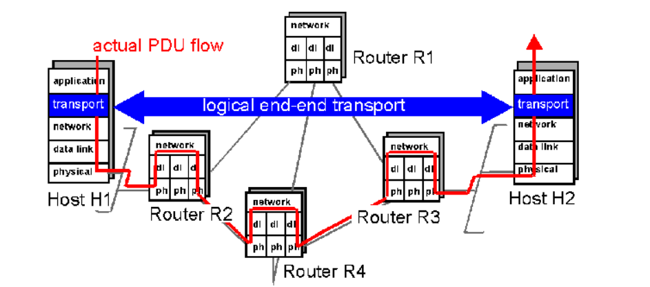
The Application processes use the logical communication provided by the transport layer to send messages to each other. The Figure illustrates the logical communication.
- As shown in the Figure the transport layer protocols are implemented in the end systems. Network routers act on the network-layer fields of the layer-3 PDUs.
- At the sending side, the transport layer converts the messages it receives from a sending application process into 4-PDUs that is, transport-layer protocol data units.
- This is done by breaking the application messages into smaller chunks and adding a transport-layer header to each chunk to create 4-PDUs.
- The transport layer then passes the 4-PDUs to the network layer, where each 4-PDU is encapsulated into a 3-PDU. At the receiving side, the transport layer receives the 4-PDUs from the network layer, removes the transport header from the 4-PDUs, reassembles the messages and passes them to a receiving application process.
COTS:
- A connection-oriented service is a technique that is used to transport data at the session layer. Unlike its opposite, connectionless service, connection-oriented service requires that a session connection be established between sender and receiver which is analogous to phone call.
- This method is normally considered to be more reliable than a connectionless service, although all connection-oriented protocols are reliable.
- A connection-oriented service can be a circuit-switched connection or a virtual circuit connection in a packet-switched network. For the latter, traffic flows are identified by a connection identifier, typically a small integer of 10 to 24 bits.
TCP Header:
TCP Header Format
TCP segments are sent as internet datagrams. The Internet Protocol header carries several information fields including the source and destination host addresses .
A TCP header follows the internet header, supplying information specific to the TCP protocol. This division allows for the existence of host level protocols other than TCP.
TCP Header Format
0 1 2 3
0 1 2 3 4 5 6 7 8 9 0 1 2 3 4 5 6 7 8 9 0 1 2 3 4 5 6 7 8 9 0 1
+-+-+-+-+-+-+-+-+-+-+-+-+-+-+-+-+-+-+-+-+-+-+-+-+-+-+-+-+-+-+-+-+
| Source Port | Destination Port |
+-+-+-+-+-+-+-+-+-+-+-+-+-+-+-+-+-+-+-+-+-+-+-+-+-+-+-+-+-+-+-+-+
| Sequence Number |
+-+-+-+-+-+-+-+-+-+-+-+-+-+-+-+-+-+-+-+-+-+-+-+-+-+-+-+-+-+-+-+-+
| Acknowledgment Number |
+-+-+-+-+-+-+-+-+-+-+-+-+-+-+-+-+-+-+-+-+-+-+-+-+-+-+-+-+-+-+-+-+
| Data | |U|A|P|R|S|F| |
| Offset| Reserved |R|C|S|S|Y|I| Window |
| | |G|K|H|T|N|N| |
+-+-+-+-+-+-+-+-+-+-+-+-+-+-+-+-+-+-+-+-+-+-+-+-+-+-+-+-+-+-+-+-+
| Checksum | Urgent Pointer |
+-+-+-+-+-+-+-+-+-+-+-+-+-+-+-+-+-+-+-+-+-+-+-+-+-+-+-+-+-+-+-+-+
| Options | Padding |
+-+-+-+-+-+-+-+-+-+-+-+-+-+-+-+-+-+-+-+-+-+-+-+-+-+-+-+-+-+-+-+-+
| data |
+-+-+-+-+-+-+-+-+-+-+-+-+-+-+-+-+-+-+-+-+-+-+-+-+-+-+-+-+-+-+-+-+
TCP Header Format
Source Port: 16 bits
The source port number.
Destination Port: 16 bits
The destination port number.
Sequence Number: 32 bits
The sequence number of the first data octet in this segment
If SYN is present the sequence number is the initial sequence number (ISN) and
The first data octet is ISN+1.
Acknowledgment Number: 32 bits
If the ACK control bit is set this field contains the value of the next sequence number the sender of the segment is expecting to receive. Once a connection is established this is always sent.
Data Offset: 4 bits
The number of 32 bit words in the TCP Header. This indicates where the data begins. The TCP header (even one including options) is an integral number of 32 bits long.
Reserved: 6 bits
Reserved for future use. Must be zero.
Control Bits: 6 bits (from left to right):
URG: Urgent Pointer field significant
ACK: Acknowledgment field significant
PSH: Push Function
RST: Reset the connection
SYN: Synchronize sequence numbers
FIN: No more data from sender
Window: 16 bits
The number of data octets beginning with the one indicated in the acknowledgment field which the sender of this segment is willing to accept.
Checksum: 16 bits
The checksum field is the 16 bit one's complement of the one's complement which is the sum of all 16 bit words in the header and text. If a segment contains an odd number of header and text octets to be checksummed, the last octet is padded on the right with zeros to form a 16- bit word for checksum purposes. The pad is not transmitted as part of the segment. While computing the check sum, the checksum field itself is replaced with zeros.
+--------+--------+--------+--------+
| Source Address |
+--------+--------+--------+--------+
| Destination Address |
+--------+--------+--------+--------+
| zero | PTCL | TCP Length |
+--------+--------+--------+--------+
Urgent Pointer: 16 bits
This field communicates the current value of the urgent pointer as a positive offset from the sequence number in this segment. The urgent pointer points to the sequence number of the octet following the urgent data. This field is only be interpreted in segments with the URG control bit set.
Services
TCP offers following services to the processes at the application layer:
- Stream Delivery Service
- Sending and Receiving Buffers
- Bytes and Segments
- Full Duplex Service
- Connection Oriented Service
- Reliable Service
Stream Delivery Service
TCP protocol is stream oriented because it allows the sending process to send data as stream of bytes and the receiving process to obtain data as stream of bytes.
Sending and Receiving Buffers
For sending and receiving process to produce and obtain data at same speed the TCP needs buffers for storage at sending and receiving ends.
Bytes and Segments
The Transmission Control Protocol (TCP), at transport layer groups the bytes into a packet. This packet is called segment. Before transmission of these packets, these segments are encapsulated into an IP datagram.
Full Duplex Service
Transmitting the data in duplex mode means flow of data in both the directions at the same time.
Connection Oriented Service
TCP offers connection- oriented service in the following manner:
- TCP of process-1 informs TCP of process – 2 and gets its approval.
- TCP of process – 1 and TCP of process – 2 exchange data in both the two directions.
- After completing the data exchange, when buffers on both sides are empty, the two TCP’s destroy their buffers.
Reliable Service
For sake of reliability, TCP uses acknowledgement mechanism.
Segments
TCP divides a stream of data into chunks, and then adds a TCP header to each chunk to create a TCP segment. A TCP segment consists of a header and a data section.
The TCP header contains 10 mandatory fields, and an optional extension field. The payload data follows the header and contains the data for the application.
Connection Establishment
The Sender starts the process with following:
Sequence number (Seq=521) which contains the random initial sequence number which generated at sender side.
Syn flag (Syn=1) s the request receiver to synchronize its sequence number with provided sequence number.
Maximum segment size (MSS=1460 B): The sender tells its maximum segment size so that receiver sends datagram which will not require any fragmentation.
MSS field is present inside Option field in TCP header.
Window size (window=14600 B): The sender tells about the buffer capacity in which he stores messages from receiver.
TCP is a full duplex protocol so both sender and receiver require a window for receiving messages from one another.
Sequence number (Seq=2000): contains the random initial sequence number which is generated at receiver side.
Syn flag (Syn=1): It is the request sent to synchronize its sequence number with the provided sequence number.
Maximum segment size (MSS=500 B): This segment sender tells its maximum segment size, so that receiver sends datagram which does not require any fragmentation. MSS field is present inside Option field in TCP header.
Window size (window=10000 B): The receiver tells about his buffer capacity in which he has to store messages from sender.
ACK flag (ACk=1): tells that acknowledgement number field contains the next sequence expected by receiver.
Flow Control:
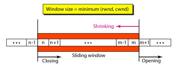
TCP uses a sliding window to handle flow control. The sliding window protocol used by TCP is something between the Go-Back-N and Selective Repeat sliding window.
The following figure shows the sliding window in TCP.
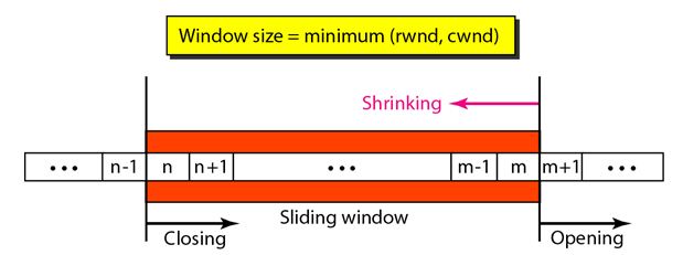
The window spans a portion of the buffer containing bytes received from the process. The bytes inside the window are the bytes that can be in transit; they can be sent without worrying about acknowledgment. The imaginary window has two walls: one left and one right.
Opening a window means moving the right wall to the right. This allows more new bytes in the buffer that are eligible for sending. Closing the window means moving the left wall to the right.
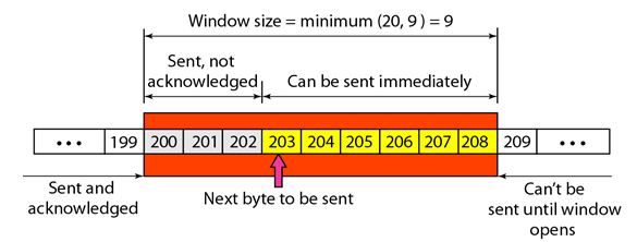
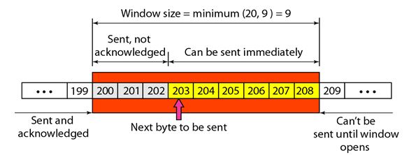
The size of the window at one end is determined by the lesser of two values: receiver window (rwnd) or congestion window (cwnd).
The receiver window is the value advertised by the opposite end in a segment containing acknowledgment. It is the number of bytes the other end can accept before its buffer overflows and data are discarded.
The following figure shows an unrealistic example of a sliding window.
Congestion Control
TCP uses a congestion window and a congestion policy that avoid congestion
On assumption that only receiver can dictate the sender’s window size we ignored another entity here which is the network.
If the network cannot deliver the data as fast as it is created by the sender, it must tell the sender to slow down.
In other words, in addition to the receiver, the network is a second entity that determines the size of the sender’s window.
Congestion policy in TCP –
- Slow Start Phase: starts slowly increment is exponential to threshold
- Congestion Avoidance Phase: After reaching the threshold increment is by 1
- Congestion Detection Phase: Sender goes back to Slow start phase or Congestion avoidance phase.
Congestion Control Algorithms:
Congestion refers to a state occurring in network layer when the message traffic is so heavy that it slows down network response time.
The Effects of Congestion are:
- As delay increases, performance decreases.
- If delay increases, retransmission occurs, making situation worse.
Leaky bucket algorithm
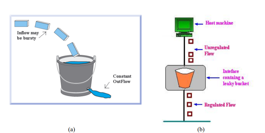
Let us imagine a bucket with a small hole in the bottom.No matter at what rate water enters the bucket, the outflow is at constant rate.When the bucket is full with water additional water entering spills over the sides and is lost.
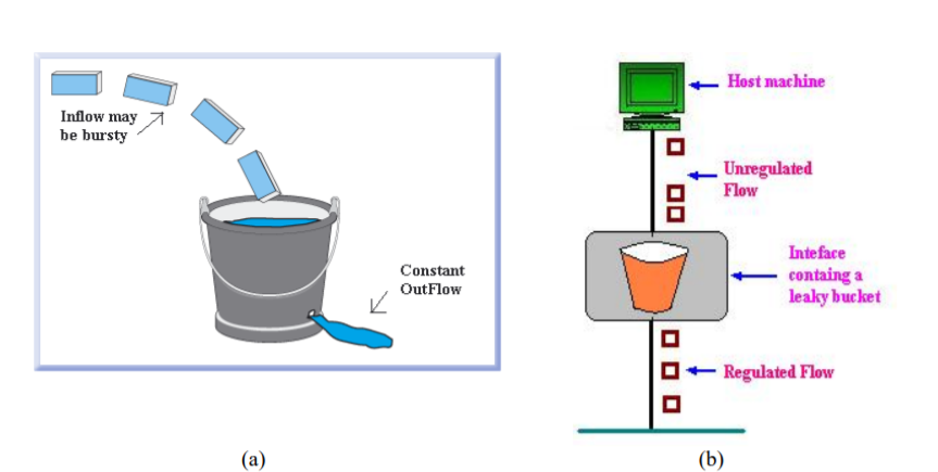
(a) – leaky bucket
(b) Implementation
Similarly, each network interface contains a leaky bucket and the following steps are involved in leaky bucket algorithm:
- When host wants to send packet, packet is thrown into the bucket.
- The bucket leaks at a constant rate, meaning the network interface transmits packets at a constant rate.
- Bursty traffic is converted to a uniform traffic by the leaky bucket.
- In practice the bucket is a finite queue that outputs at a finite rate.
- Token bucket Algorithm
The leaky bucket algorithm enforces output pattern at the average rate, no matter how bursty the traffic is. Therefore, to deal with the bursty traffic we need a flexible algorithm so that the data is not lost.
One such algorithm is token bucket algorithm.
Steps of this algorithm can be described as follows:
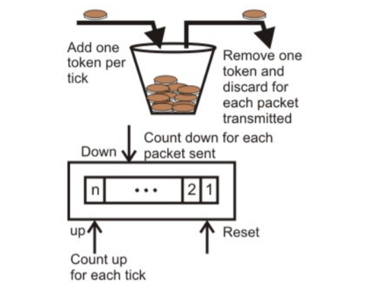
- In regular intervals tokens are thrown into the bucket. ƒ
- The bucket has a maximum capacity. ƒ
- If there is a ready packet, a token is removed from the bucket, and the packet is sent.
- If there is no token in the bucket, the packet cannot be sent.
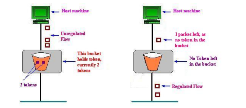
Consider In figure (a) we see a bucket holding three tokens, with five packets waiting to be transmitted. For a packet to be transmitted, it must capture and destroy one token. In figure (b) we see that three of the five packets have gotten through, but the other two are stuck waiting for more tokens to be generated.
In the token bucket, algorithm tokens are generated at each tick (up to a certain limit). For an incoming packet to be transmitted, it must capture a token and the transmission takes place at the same rate. Hence some of the busty packets are transmitted at the same rate if tokens are available and thus introduces some amount of flexibility in the system.
Formula: M * s = C + ρ * s
where S – is time taken
M – Maximum output rate
ρ – Token arrival rate
C – Capacity of the token bucket in byte
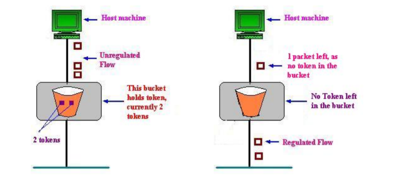
(a)Token bucket holding two tokens, before packets are send out,
(b)Token bucket after two packets are send, one packet still remains as no token is left
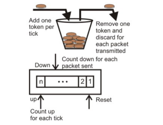
Implementation of token bucket algorithm
QoS:
Congestion management tools, including queuing tools, apply to interfaces that experience congestion. Whenever packets enter a device faster than they can exit, the potential for congestion exists and queuing mechanisms apply.
It is important that queuing tools are activated only when congestion exists. In the absence of congestion, packets are sent as soon as they arrive. However, when congestion occurs, packets must be buffered, or queued—the temporary storage and subsequent scheduling of these backed-up packets—to mitigate dropping.
After traffic is analyzed and identified which is treated by a set of actions, the next quality of service (QoS) task is to assign actions or policy treatments to these classes of traffic, including bandwidth assignments, policing, shaping, queuing, and dropping decisions.
Timers:
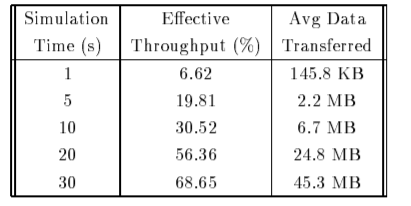
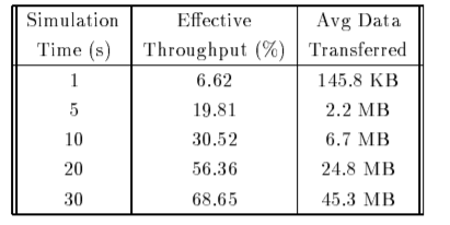
The table shows the effective throughput obtained by limiting the simulation time to different values. It indicates the resulting average amount of data transferred by each sender at that time.
These results indicate that the effective throughput of TCP transfers increases with increase in simulation time.
It also indicates that the resulting average amount of data transferred by each sender in that time. These results indicate that the effective throughput of TCP transfers increases with simulation time.
For TCP transfers it takes less than 1s of time to finish the effective throughput is less than 7% while transfers take less than 10s to finish that have effective throughput less than 30% . Large TCP transfers attains effective throughput of 70% and shall be effectively utilized for high bandwidth network.
CLTS Connectionless Transport
TS Transport Services (implies connectionless transport
Service in this memo)
TSAP Transport Service Access Point
TS-peer a process which implements the mapping of CLTS
Protocols onto the UDP interface as described by
This memo
TS-user a process using the services of a TS-provider
TS-provider the abstraction of the totality of those entities which provide the overall service between the two TS-users
UD TPDU Unit Data TPDU (Transport Protocol Data Unit)
Each TS-user gains access to the TS-provider at a TSAP.
The two TS- users can communicate with each other using a connectionless
Transport provided that there is pre-arranged knowledge about each
Other (e.g., protocol version, formats, options, ... Etc.), since
There is no negotiation before data transfer. One TS-user passes a message to the TS-provider, and the peer TS-user receives the message from the TS-provider. The interactions between TS-user and TS-provider are described by connectionless TS primitives.
UDP header :
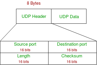
UDP header is 8-bytes fixed and has simple header. The first 8 Bytes contains all necessary header information and remaining part consist of data. UDP port number fields are each 16 bits long, therefore range for port numbers defined from 0 to 65535; port number 0 is reserved. Port numbers help to distinguish different user requests or process.
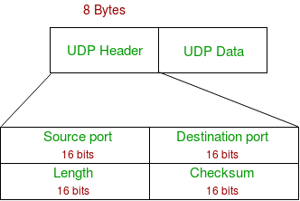
- Source Port : Source Port is 2 Byte long field used to identify port number of source.
- Destination Port : It is 2 Byte long field, used to identify the port of destined packet.
- Length : Length is the length of UDP including header and the data. It is 16-bits field.
- Checksum : Checksum is 2 Bytes long field. It is the 16-bit one’s complement of the one’s complement sum of the UDP header, pseudo header of information from the IP header and the data, padded with zero octets at the end (if necessary) to make a multiple of two octets.
UDP Datagram:
The User Datagram Protocol offers minimal transport service -- non-guaranteed datagram delivery -- and gives applications direct access to the datagram service of the IP layer.
UDP is used by applications that do not require the level of service of TCP or that wish to use communications services .
UDP is almost a null protocol which the services it provides over IP are check summing of data and multiplexing by port number.
Therefore, an application program running over UDP must deal directly with end-to-end communication problems that a connection-oriented protocol would have handled -- e.g., retransmission for reliable delivery, packetization and reassembly, flow control, congestion avoidance, etc., when these are required.
UDP Services:
- Domain Name Services.
- Simple Network Management Protocol.
- Trivial File Transfer Protocol.
- Routing Information Protocol.
- Kerberos
UDP Applications
- Lossless data transmission
- Improve data transfer rate of large files compared to TCP
- UDP works in conjunction with higher level protocols to manage data transmission services.
- Real time Streaming Protocol
- Simple Network Management Protocol.
- Gaming, voice and video communications which suffers data loss.
- Reliable exchange of information
- Multicasting and Packet switching
Socket
Primitives:
Within the socket interface, UDP is normally used with send to (), send msg(), recvfrom() and recvmsg() system calls.
If the connect() call is used to fix the destination for future packets, then the recv() or read() and send() or write() calls may be used.
A server knows who (which client) to respond to by looking at the client IP address and port contained within the received UDP header and IP header. This information is passed by the UDP entity (kernel) when a process receives a datagram.
A UDP socket may be restricted by both foreign and local address. The local address applies for to machines with more than one interface, or for receipt of UDP broadcast packets.

TCP and UDP Sockets
TCP Socket API
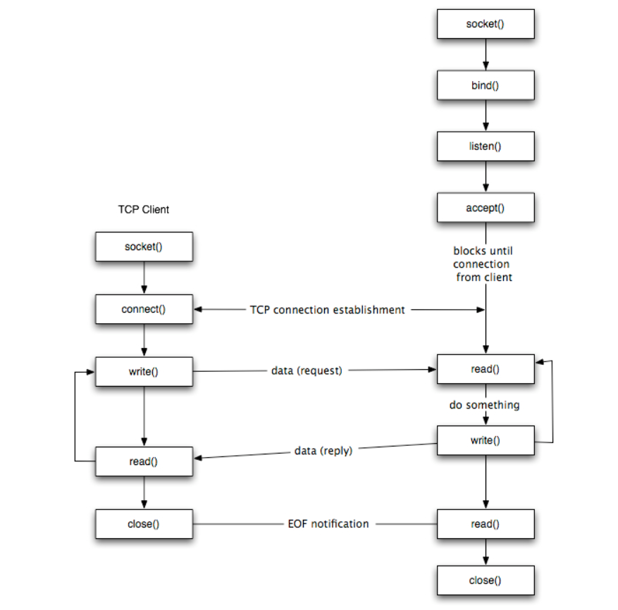
The sequence of function calls for the client and a server participating in a TCP connection is presented in Figure.
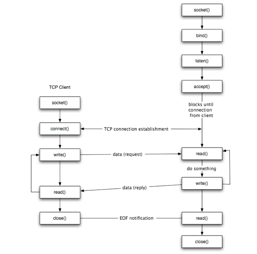
The steps for establishing a TCP socket on the client side are the following:
- Create a socket using the socket() function;
- Connect the socket to the address of the server using the connect() function;
- Send and receive data by means of the read() and write() functions.
- Close the connection by means of the close() function.
The steps involved in establishing a TCP socket on the server side are as follows:
- Create a socket with the socket() function;
- Bind the socket to an address using the bind() function;
- Listen for connections with the listen() function;
- Accept a connection with the accept() function system call. This call typically blocks until a client connects with the server.
- Send and receive data by means of send() and receive().
- Close the connection by means of the close() function.
The socket() Function
- The first step is to call the socket function, specifying the type of communication protocol (TCP based on IPv4, TCP based on IPv6, UDP).
- The function is defined as follows:
# include <sys/socket.h>
Int socket ( int family, int type, int protocol) ; where family specifies the protocol family which specifies protocol family
Type is constant described type of socket.
The connect () Function
The connect () function is used by a TCP client to establish a connection with a TCP server/
The function is defined as follows:
#include<sys/socket.h>
Int connect (int sockfd, const struct sockaddr *servaddr, socklen_t addrlen);
Where sockfd is the socket descriptor returned by the socket function.
The bind() Function
The bind() assigns a local protocol address to a socket. With the Internet protocols, the address is the combination of an IPv4 or IPv6 address (32-bit or 128-bit) address along with a 16 bit TCP port number.
The function is defined as follows:
#include<sys/socket.h>
Int bind(int sockfd, const struct sockaddr *servaddr, socklen_t addrlen);
The listen() Function
The listen() function converts an unconnected socket into a passive socket, indicating that the kernel should accept incoming connection requests directed to this socket. It is defined as follows:
#include<sys/socket.h>
Int listen(int sockfd, int backlog);
Where sockfd is the socket descriptor and backlog is the maximum number of connections the kernel should queue for this socket.
The accept() Function
The accept() is used to retrieve a connect request and convert that into a request. It is defined as follows:
#include<sys/socket.h>
Int accept (int sockfd, struct sockaddr *cliaddr, socklen_t *addrlen);
Where sockfd is a new file descriptor that is connected to the client that called the connect(). The cliaddr and addrlen arguments are used to return the protocol address of the client.
To accept() is not associated with the connection, but instead remains available to receive additional connect requests. The kernel creates one connected socket for each client connection that is accepted.
The send() Function
Since a socket endpoint is represented as a file descriptor use read and write to communicate with a socket as long as it is connected. However, if we want to specify options we need another set of functions.
For example, send() is similar to write() but allows to specify some options. send() is defined as follows:
#include<sys/socket.h>
Ssize_t_send(int sockfd, const void *buf, size_t nbytes, int flags );
Where buf and nbytes have the same meaning as they have with write. The additional argument flags is used to specify how we want the data to be transmitted.
The receive() Function
The recv() function is similar to read(), but allows to specify some options to control how the data are received. We will not consider the possible options in this course. We will assume it equal to 0.
Receive is defined as follows:
#include<sys/socket.h>
Ssize_t_recv(int sockfd, void *buf,size_t nbytes, int flags);
The function returns the length of the message in bytes, 0 if no messages are available and peer had done an orderly shutdown, or -1 on error.
The close() Function
The normal close() function is used to close a socket and terminate a TCP socket. It returns 0 if it succeeds, -1 on error. It is defined as follows:
#include<unistd.h>
Int close(int sockfd);
UDP socket
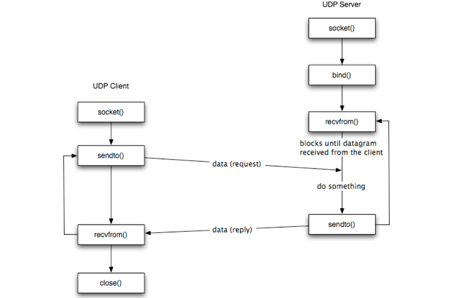
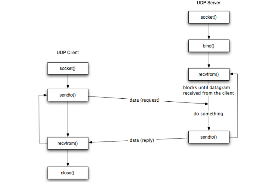
The figure shows the interaction between a UDP client and server. The client does not establish a connection with the server instead, the client just sends a datagram to the server using sendto function which requires the address of the destination as a parameter.
Similarly, the server does not accept a connection from a client. Instead, the server just calls the recvfrom function which waits until data arrives from some client. recvfrom returns the IP address of the client, along with the datagram, so the server can send a response to the client.
The steps of establishing a UDP socket communication on the client side are as follows:
- Create a socket using the socket() function;
- Send and receive data by means of the recvfrom() and sendto() functions.
The steps of establishing a UDP socket communication on the server side are as follows:
- Create a socket with the socket() function;
- Bind the socket to an address using the bind() function;
- Send and receive data by means of recvfrom() and sendto().
The recvfrom() Function
This function is similar to the read() function, but three additional arguments are required. The recvfrom() function is defined as follows:
#include<sys/socket.h>
Ssize_t recvfrom(int sockfd void* buff, size_t nbytes, int flags, struct sock addr* from socklen t *addrlen);
The first three arguments sockfd, buff, and nbytes, are identical to the first three arguments of read and write. sockfd is the socket descriptor, buff is the pointer to read into, and nbytes is number of bytes to read.
The sendto() Function
This function is similar to the send() function, but three additional arguments are required. The sendto() function is defined as follows:
#incude<sys/socket.h>
Ssize_t recvfrom(int sockfd void* buff, size_t nbytes, int flags, struct sock addr* to socklen t *addrlen);
The first three arguments sockfd, buff, and nbytes, are identical to the first three arguments of recv. sockfd is the socket descriptor, buff is the pointer to write from, and nbytes is number of bytes to write.
The fork() function
The fork() function is the only way in Unix to create a new process. It is defined as follows:
#include<units.h>
Pid_t fors(void);
The function returns 0 if in child and the process ID of the child in parent; otherwise, -1 on error.
Client Server model using simple socket Programming.
The Client–Server model of computing is a distributed application that partitions tasks or workloads between the providers of a resource or service, called servers, and service requesters, called clients.
Often clients and servers communicate over a computer network on separate hardware, but both client and server may reside in the same system.
A server machine is a host that is running one or more server programs which share their resources with clients. A client does not share any of its resources but requests a server’s content or service function. Clients therefore initiate communication sessions with servers which await incoming requests.
Socket Programming
A socket is one of the most fundamental technologies of computer networking. Sockets allow applications to communicate using standard mechanisms built into network hardware and operating systems.
A socket represents a single connection between exactly two pieces of software. More than two pieces of software can communicate in client/server or distributed systems (for example, many Web browsers can simultaneously communicate with a single Web server) but multiple sockets are required to do this. Sockets are bidirectional, meaning that either side of the connection is capable of both sending and receiving data. Libraries implementing sockets for Internet Protocol
Use TCP for streams, UDP for datagrams, and IP itself for raw sockets.
For opening socket at the client end
Following syntax is used:
Socket MyClient;
MyClient=new Socket(“Server IP”,Portnumber);
Where server IP is the machine where the client is trying to connect, and Portnumber is the port (a number) on which the server trying to connect to is running. When selecting a port number, the port numbers between 0 and 1,023 are reserved for privileged users (that is, super user or root). These port numbers are reserved for standard services, such as email, FTP, and HTTP.
When selecting a port number for your server, select one that is greater than 1,023!
Open socket at server end. Following syntax is used.
ServerSocket Myserver;
Myserver=new ServerSocket(“Portnumber”);
3. When implementing a server there is a need to create a socket object from the ServerSocket to listen for and accept connections from clients.
ServiceScoket=Myserver.accept();
4.On the client side, DataInputStream class can be used to create an input stream to receive response from the server:
DataInputStream input;
Input=new DataInputStream(MyClient.getInputStream());
The class DataInputStream allows to read lines of text and Java primitive data types in a portable way. It has methods such as read, readChar, readInt, readDouble,and readLine,. Use whichever function you think suits your needs depending on the type of data that you receive from the server.
5. On the server side, DataInputStream can be used to receive input from the client:
DataInputStream input;
Input=new DataInputStream(ServiceSocket.getInputStream());
6. On the client side, an output stream is created to send information to the server socket using the class PrintStream or DataOutputStream of java.io:
PrintStream output;
Output=new PrintStream(MyClient.getOutputStream());
The class PrintStream has Write and println methods for displaying textual representation of Java primitive data types.
7. On the server side, you can use the class PrintStream to send information to the client.
PrintStream output;
Output=new PrintStream(ServiceSocket.getOutputStream());
8. You should always close the output and input stream before you close the socket.
Output.close();
Input.close();
Myclient.close();
On server side:
Output.close();
Input.close();
ServiceSocket.close();
Case Study on Transport Layer Security – Firewall (Stateless Packet)
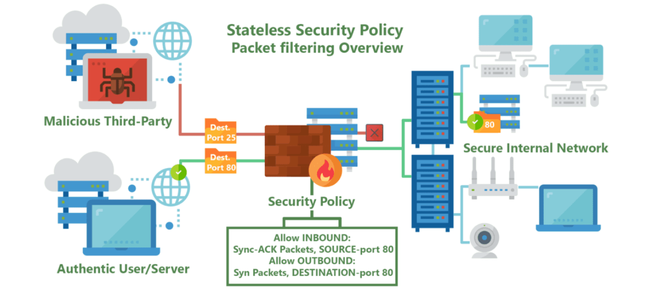
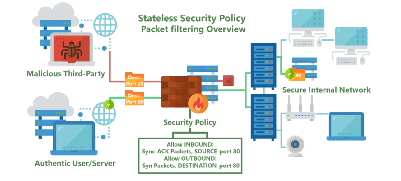
Stateless firewalls are some of the oldest firewalls on the market and have been around for almost as long as the web itself. The purpose of stateless firewalls is to protect computers and networks — specifically: routing engine processes and resources. They provide this security by filtering the packets of incoming traffic distinguishing between udp/tcp traffic and port numbers. The packets are either allowed entry onto the network or denied access based either their source or destination address or some other static information such as the traffic type (udp/tcp).These days completely stateless firewalls are far and few inbetween.
The most commonly seen in the form of CPE’s (modems/router combos) given to customers by typical service providers. This equipment, usually given to residential internet consumers, provide simple firewalls using packet filtering and port forwarding functionality built on top of low-power CPE’s.
Providing very basic but powerful security restricting incoming and outgoing traffic useful to protect commonly abused ports often by self-propagating or DDOSing malware, such as ports 443, 53, 80 and 25.
This blanket port filtering is implemented using white-lists allowing only a few key ports for application-specific traffic such as VoIP, as 90% of all internet traffic traverses with the Hyper-Text Transfer Protocol (HTTP) through proxy requests to Domain Name Servers (DNS).
In cases when hosting servers for multiplayer video games, email/web services, or live-streaming video, users must manually configure these firewalls outside of their default security policy to allow different ports & applications through the filter.
References:
Tcp/Ip Protocol Suite Book by Behrouz A. Forouzan
Open Systems Networking: TCP/IP and OSI Book by David M. Piscitello and Lyman Chapin
Patterns in Network Architecture: A Return to Fundamentals Book by John Day
Unit 6
Transport Layer – Services and Protocols
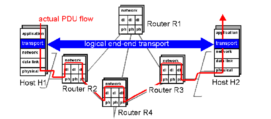
- A transport layer protocol provides for logical communication between application processes running on different hosts. Logical communication means that although the communicating application processes are not physically connected to each other it is as if they were physically connected.
The Application processes use the logical communication provided by the transport layer to send messages to each other. The Figure illustrates the logical communication.
- As shown in the Figure the transport layer protocols are implemented in the end systems. Network routers act on the network-layer fields of the layer-3 PDUs.
- At the sending side, the transport layer converts the messages it receives from a sending application process into 4-PDUs that is, transport-layer protocol data units.
- This is done by breaking the application messages into smaller chunks and adding a transport-layer header to each chunk to create 4-PDUs.
- The transport layer then passes the 4-PDUs to the network layer, where each 4-PDU is encapsulated into a 3-PDU. At the receiving side, the transport layer receives the 4-PDUs from the network layer, removes the transport header from the 4-PDUs, reassembles the messages and passes them to a receiving application process.
COTS:
- A connection-oriented service is a technique that is used to transport data at the session layer. Unlike its opposite, connectionless service, connection-oriented service requires that a session connection be established between sender and receiver which is analogous to phone call.
- This method is normally considered to be more reliable than a connectionless service, although all connection-oriented protocols are reliable.
- A connection-oriented service can be a circuit-switched connection or a virtual circuit connection in a packet-switched network. For the latter, traffic flows are identified by a connection identifier, typically a small integer of 10 to 24 bits.
TCP Header:
TCP Header Format
TCP segments are sent as internet datagrams. The Internet Protocol header carries several information fields including the source and destination host addresses .
A TCP header follows the internet header, supplying information specific to the TCP protocol. This division allows for the existence of host level protocols other than TCP.
TCP Header Format
0 1 2 3
0 1 2 3 4 5 6 7 8 9 0 1 2 3 4 5 6 7 8 9 0 1 2 3 4 5 6 7 8 9 0 1
+-+-+-+-+-+-+-+-+-+-+-+-+-+-+-+-+-+-+-+-+-+-+-+-+-+-+-+-+-+-+-+-+
| Source Port | Destination Port |
+-+-+-+-+-+-+-+-+-+-+-+-+-+-+-+-+-+-+-+-+-+-+-+-+-+-+-+-+-+-+-+-+
| Sequence Number |
+-+-+-+-+-+-+-+-+-+-+-+-+-+-+-+-+-+-+-+-+-+-+-+-+-+-+-+-+-+-+-+-+
| Acknowledgment Number |
+-+-+-+-+-+-+-+-+-+-+-+-+-+-+-+-+-+-+-+-+-+-+-+-+-+-+-+-+-+-+-+-+
| Data | |U|A|P|R|S|F| |
| Offset| Reserved |R|C|S|S|Y|I| Window |
| | |G|K|H|T|N|N| |
+-+-+-+-+-+-+-+-+-+-+-+-+-+-+-+-+-+-+-+-+-+-+-+-+-+-+-+-+-+-+-+-+
| Checksum | Urgent Pointer |
+-+-+-+-+-+-+-+-+-+-+-+-+-+-+-+-+-+-+-+-+-+-+-+-+-+-+-+-+-+-+-+-+
| Options | Padding |
+-+-+-+-+-+-+-+-+-+-+-+-+-+-+-+-+-+-+-+-+-+-+-+-+-+-+-+-+-+-+-+-+
| data |
+-+-+-+-+-+-+-+-+-+-+-+-+-+-+-+-+-+-+-+-+-+-+-+-+-+-+-+-+-+-+-+-+
TCP Header Format
Source Port: 16 bits
The source port number.
Destination Port: 16 bits
The destination port number.
Sequence Number: 32 bits
The sequence number of the first data octet in this segment
If SYN is present the sequence number is the initial sequence number (ISN) and
The first data octet is ISN+1.
Acknowledgment Number: 32 bits
If the ACK control bit is set this field contains the value of the next sequence number the sender of the segment is expecting to receive. Once a connection is established this is always sent.
Data Offset: 4 bits
The number of 32 bit words in the TCP Header. This indicates where the data begins. The TCP header (even one including options) is an integral number of 32 bits long.
Reserved: 6 bits
Reserved for future use. Must be zero.
Control Bits: 6 bits (from left to right):
URG: Urgent Pointer field significant
ACK: Acknowledgment field significant
PSH: Push Function
RST: Reset the connection
SYN: Synchronize sequence numbers
FIN: No more data from sender
Window: 16 bits
The number of data octets beginning with the one indicated in the acknowledgment field which the sender of this segment is willing to accept.
Checksum: 16 bits
The checksum field is the 16 bit one's complement of the one's complement which is the sum of all 16 bit words in the header and text. If a segment contains an odd number of header and text octets to be checksummed, the last octet is padded on the right with zeros to form a 16- bit word for checksum purposes. The pad is not transmitted as part of the segment. While computing the check sum, the checksum field itself is replaced with zeros.
+--------+--------+--------+--------+
| Source Address |
+--------+--------+--------+--------+
| Destination Address |
+--------+--------+--------+--------+
| zero | PTCL | TCP Length |
+--------+--------+--------+--------+
Urgent Pointer: 16 bits
This field communicates the current value of the urgent pointer as a positive offset from the sequence number in this segment. The urgent pointer points to the sequence number of the octet following the urgent data. This field is only be interpreted in segments with the URG control bit set.
Services
TCP offers following services to the processes at the application layer:
- Stream Delivery Service
- Sending and Receiving Buffers
- Bytes and Segments
- Full Duplex Service
- Connection Oriented Service
- Reliable Service
Stream Delivery Service
TCP protocol is stream oriented because it allows the sending process to send data as stream of bytes and the receiving process to obtain data as stream of bytes.
Sending and Receiving Buffers
For sending and receiving process to produce and obtain data at same speed the TCP needs buffers for storage at sending and receiving ends.
Bytes and Segments
The Transmission Control Protocol (TCP), at transport layer groups the bytes into a packet. This packet is called segment. Before transmission of these packets, these segments are encapsulated into an IP datagram.
Full Duplex Service
Transmitting the data in duplex mode means flow of data in both the directions at the same time.
Connection Oriented Service
TCP offers connection- oriented service in the following manner:
- TCP of process-1 informs TCP of process – 2 and gets its approval.
- TCP of process – 1 and TCP of process – 2 exchange data in both the two directions.
- After completing the data exchange, when buffers on both sides are empty, the two TCP’s destroy their buffers.
Reliable Service
For sake of reliability, TCP uses acknowledgement mechanism.
Segments
TCP divides a stream of data into chunks, and then adds a TCP header to each chunk to create a TCP segment. A TCP segment consists of a header and a data section.
The TCP header contains 10 mandatory fields, and an optional extension field. The payload data follows the header and contains the data for the application.
Connection Establishment
The Sender starts the process with following:
Sequence number (Seq=521) which contains the random initial sequence number which generated at sender side.
Syn flag (Syn=1) s the request receiver to synchronize its sequence number with provided sequence number.
Maximum segment size (MSS=1460 B): The sender tells its maximum segment size so that receiver sends datagram which will not require any fragmentation.
MSS field is present inside Option field in TCP header.
Window size (window=14600 B): The sender tells about the buffer capacity in which he stores messages from receiver.
TCP is a full duplex protocol so both sender and receiver require a window for receiving messages from one another.
Sequence number (Seq=2000): contains the random initial sequence number which is generated at receiver side.
Syn flag (Syn=1): It is the request sent to synchronize its sequence number with the provided sequence number.
Maximum segment size (MSS=500 B): This segment sender tells its maximum segment size, so that receiver sends datagram which does not require any fragmentation. MSS field is present inside Option field in TCP header.
Window size (window=10000 B): The receiver tells about his buffer capacity in which he has to store messages from sender.
ACK flag (ACk=1): tells that acknowledgement number field contains the next sequence expected by receiver.
Flow Control:
TCP uses a sliding window to handle flow control. The sliding window protocol used by TCP is something between the Go-Back-N and Selective Repeat sliding window.
The following figure shows the sliding window in TCP.
The window spans a portion of the buffer containing bytes received from the process. The bytes inside the window are the bytes that can be in transit; they can be sent without worrying about acknowledgment. The imaginary window has two walls: one left and one right.
Opening a window means moving the right wall to the right. This allows more new bytes in the buffer that are eligible for sending. Closing the window means moving the left wall to the right.
The size of the window at one end is determined by the lesser of two values: receiver window (rwnd) or congestion window (cwnd).
The receiver window is the value advertised by the opposite end in a segment containing acknowledgment. It is the number of bytes the other end can accept before its buffer overflows and data are discarded.
The following figure shows an unrealistic example of a sliding window.
Congestion Control
TCP uses a congestion window and a congestion policy that avoid congestion
On assumption that only receiver can dictate the sender’s window size we ignored another entity here which is the network.
If the network cannot deliver the data as fast as it is created by the sender, it must tell the sender to slow down.
In other words, in addition to the receiver, the network is a second entity that determines the size of the sender’s window.
Congestion policy in TCP –
- Slow Start Phase: starts slowly increment is exponential to threshold
- Congestion Avoidance Phase: After reaching the threshold increment is by 1
- Congestion Detection Phase: Sender goes back to Slow start phase or Congestion avoidance phase.
Congestion Control Algorithms:
Congestion refers to a state occurring in network layer when the message traffic is so heavy that it slows down network response time.
The Effects of Congestion are:
- As delay increases, performance decreases.
- If delay increases, retransmission occurs, making situation worse.
Leaky bucket algorithm
Let us imagine a bucket with a small hole in the bottom.No matter at what rate water enters the bucket, the outflow is at constant rate.When the bucket is full with water additional water entering spills over the sides and is lost.
(a) – leaky bucket
(b) Implementation
Similarly, each network interface contains a leaky bucket and the following steps are involved in leaky bucket algorithm:
- When host wants to send packet, packet is thrown into the bucket.
- The bucket leaks at a constant rate, meaning the network interface transmits packets at a constant rate.
- Bursty traffic is converted to a uniform traffic by the leaky bucket.
- In practice the bucket is a finite queue that outputs at a finite rate.
- Token bucket Algorithm
The leaky bucket algorithm enforces output pattern at the average rate, no matter how bursty the traffic is. Therefore, to deal with the bursty traffic we need a flexible algorithm so that the data is not lost.
One such algorithm is token bucket algorithm.
Steps of this algorithm can be described as follows:
- In regular intervals tokens are thrown into the bucket. ƒ
- The bucket has a maximum capacity. ƒ
- If there is a ready packet, a token is removed from the bucket, and the packet is sent.
- If there is no token in the bucket, the packet cannot be sent.
Consider In figure (a) we see a bucket holding three tokens, with five packets waiting to be transmitted. For a packet to be transmitted, it must capture and destroy one token. In figure (b) we see that three of the five packets have gotten through, but the other two are stuck waiting for more tokens to be generated.
In the token bucket, algorithm tokens are generated at each tick (up to a certain limit). For an incoming packet to be transmitted, it must capture a token and the transmission takes place at the same rate. Hence some of the busty packets are transmitted at the same rate if tokens are available and thus introduces some amount of flexibility in the system.
Formula: M * s = C + ρ * s
where S – is time taken
M – Maximum output rate
ρ – Token arrival rate
C – Capacity of the token bucket in byte
(a)Token bucket holding two tokens, before packets are send out,
(b)Token bucket after two packets are send, one packet still remains as no token is left
Implementation of token bucket algorithm
QoS:
Congestion management tools, including queuing tools, apply to interfaces that experience congestion. Whenever packets enter a device faster than they can exit, the potential for congestion exists and queuing mechanisms apply.
It is important that queuing tools are activated only when congestion exists. In the absence of congestion, packets are sent as soon as they arrive. However, when congestion occurs, packets must be buffered, or queued—the temporary storage and subsequent scheduling of these backed-up packets—to mitigate dropping.
After traffic is analyzed and identified which is treated by a set of actions, the next quality of service (QoS) task is to assign actions or policy treatments to these classes of traffic, including bandwidth assignments, policing, shaping, queuing, and dropping decisions.
Timers:
The table shows the effective throughput obtained by limiting the simulation time to different values. It indicates the resulting average amount of data transferred by each sender at that time.
These results indicate that the effective throughput of TCP transfers increases with increase in simulation time.
It also indicates that the resulting average amount of data transferred by each sender in that time. These results indicate that the effective throughput of TCP transfers increases with simulation time.
For TCP transfers it takes less than 1s of time to finish the effective throughput is less than 7% while transfers take less than 10s to finish that have effective throughput less than 30% . Large TCP transfers attains effective throughput of 70% and shall be effectively utilized for high bandwidth network.
CLTS Connectionless Transport
TS Transport Services (implies connectionless transport
Service in this memo)
TSAP Transport Service Access Point
TS-peer a process which implements the mapping of CLTS
Protocols onto the UDP interface as described by
This memo
TS-user a process using the services of a TS-provider
TS-provider the abstraction of the totality of those entities which provide the overall service between the two TS-users
UD TPDU Unit Data TPDU (Transport Protocol Data Unit)
Each TS-user gains access to the TS-provider at a TSAP.
The two TS- users can communicate with each other using a connectionless
Transport provided that there is pre-arranged knowledge about each
Other (e.g., protocol version, formats, options, ... Etc.), since
There is no negotiation before data transfer. One TS-user passes a message to the TS-provider, and the peer TS-user receives the message from the TS-provider. The interactions between TS-user and TS-provider are described by connectionless TS primitives.
UDP header :
UDP header is 8-bytes fixed and has simple header. The first 8 Bytes contains all necessary header information and remaining part consist of data. UDP port number fields are each 16 bits long, therefore range for port numbers defined from 0 to 65535; port number 0 is reserved. Port numbers help to distinguish different user requests or process.
- Source Port : Source Port is 2 Byte long field used to identify port number of source.
- Destination Port : It is 2 Byte long field, used to identify the port of destined packet.
- Length : Length is the length of UDP including header and the data. It is 16-bits field.
- Checksum : Checksum is 2 Bytes long field. It is the 16-bit one’s complement of the one’s complement sum of the UDP header, pseudo header of information from the IP header and the data, padded with zero octets at the end (if necessary) to make a multiple of two octets.
UDP Datagram:
The User Datagram Protocol offers minimal transport service -- non-guaranteed datagram delivery -- and gives applications direct access to the datagram service of the IP layer.
UDP is used by applications that do not require the level of service of TCP or that wish to use communications services .
UDP is almost a null protocol which the services it provides over IP are check summing of data and multiplexing by port number.
Therefore, an application program running over UDP must deal directly with end-to-end communication problems that a connection-oriented protocol would have handled -- e.g., retransmission for reliable delivery, packetization and reassembly, flow control, congestion avoidance, etc., when these are required.
UDP Services:
- Domain Name Services.
- Simple Network Management Protocol.
- Trivial File Transfer Protocol.
- Routing Information Protocol.
- Kerberos
UDP Applications
- Lossless data transmission
- Improve data transfer rate of large files compared to TCP
- UDP works in conjunction with higher level protocols to manage data transmission services.
- Real time Streaming Protocol
- Simple Network Management Protocol.
- Gaming, voice and video communications which suffers data loss.
- Reliable exchange of information
- Multicasting and Packet switching
Socket
Primitives:
Within the socket interface, UDP is normally used with send to (), send msg(), recvfrom() and recvmsg() system calls.
If the connect() call is used to fix the destination for future packets, then the recv() or read() and send() or write() calls may be used.
A server knows who (which client) to respond to by looking at the client IP address and port contained within the received UDP header and IP header. This information is passed by the UDP entity (kernel) when a process receives a datagram.
A UDP socket may be restricted by both foreign and local address. The local address applies for to machines with more than one interface, or for receipt of UDP broadcast packets.

TCP and UDP Sockets
TCP Socket API
The sequence of function calls for the client and a server participating in a TCP connection is presented in Figure.
The steps for establishing a TCP socket on the client side are the following:
- Create a socket using the socket() function;
- Connect the socket to the address of the server using the connect() function;
- Send and receive data by means of the read() and write() functions.
- Close the connection by means of the close() function.
The steps involved in establishing a TCP socket on the server side are as follows:
- Create a socket with the socket() function;
- Bind the socket to an address using the bind() function;
- Listen for connections with the listen() function;
- Accept a connection with the accept() function system call. This call typically blocks until a client connects with the server.
- Send and receive data by means of send() and receive().
- Close the connection by means of the close() function.
The socket() Function
- The first step is to call the socket function, specifying the type of communication protocol (TCP based on IPv4, TCP based on IPv6, UDP).
- The function is defined as follows:
# include <sys/socket.h>
Int socket ( int family, int type, int protocol) ; where family specifies the protocol family which specifies protocol family
Type is constant described type of socket.
The connect () Function
The connect () function is used by a TCP client to establish a connection with a TCP server/
The function is defined as follows:
#include<sys/socket.h>
Int connect (int sockfd, const struct sockaddr *servaddr, socklen_t addrlen);
Where sockfd is the socket descriptor returned by the socket function.
The bind() Function
The bind() assigns a local protocol address to a socket. With the Internet protocols, the address is the combination of an IPv4 or IPv6 address (32-bit or 128-bit) address along with a 16 bit TCP port number.
The function is defined as follows:
#include<sys/socket.h>
Int bind(int sockfd, const struct sockaddr *servaddr, socklen_t addrlen);
The listen() Function
The listen() function converts an unconnected socket into a passive socket, indicating that the kernel should accept incoming connection requests directed to this socket. It is defined as follows:
#include<sys/socket.h>
Int listen(int sockfd, int backlog);
Where sockfd is the socket descriptor and backlog is the maximum number of connections the kernel should queue for this socket.
The accept() Function
The accept() is used to retrieve a connect request and convert that into a request. It is defined as follows:
#include<sys/socket.h>
Int accept (int sockfd, struct sockaddr *cliaddr, socklen_t *addrlen);
Where sockfd is a new file descriptor that is connected to the client that called the connect(). The cliaddr and addrlen arguments are used to return the protocol address of the client.
To accept() is not associated with the connection, but instead remains available to receive additional connect requests. The kernel creates one connected socket for each client connection that is accepted.
The send() Function
Since a socket endpoint is represented as a file descriptor use read and write to communicate with a socket as long as it is connected. However, if we want to specify options we need another set of functions.
For example, send() is similar to write() but allows to specify some options. send() is defined as follows:
#include<sys/socket.h>
Ssize_t_send(int sockfd, const void *buf, size_t nbytes, int flags );
Where buf and nbytes have the same meaning as they have with write. The additional argument flags is used to specify how we want the data to be transmitted.
The receive() Function
The recv() function is similar to read(), but allows to specify some options to control how the data are received. We will not consider the possible options in this course. We will assume it equal to 0.
Receive is defined as follows:
#include<sys/socket.h>
Ssize_t_recv(int sockfd, void *buf,size_t nbytes, int flags);
The function returns the length of the message in bytes, 0 if no messages are available and peer had done an orderly shutdown, or -1 on error.
The close() Function
The normal close() function is used to close a socket and terminate a TCP socket. It returns 0 if it succeeds, -1 on error. It is defined as follows:
#include<unistd.h>
Int close(int sockfd);
UDP socket
The figure shows the interaction between a UDP client and server. The client does not establish a connection with the server instead, the client just sends a datagram to the server using sendto function which requires the address of the destination as a parameter.
Similarly, the server does not accept a connection from a client. Instead, the server just calls the recvfrom function which waits until data arrives from some client. recvfrom returns the IP address of the client, along with the datagram, so the server can send a response to the client.
The steps of establishing a UDP socket communication on the client side are as follows:
- Create a socket using the socket() function;
- Send and receive data by means of the recvfrom() and sendto() functions.
The steps of establishing a UDP socket communication on the server side are as follows:
- Create a socket with the socket() function;
- Bind the socket to an address using the bind() function;
- Send and receive data by means of recvfrom() and sendto().
The recvfrom() Function
This function is similar to the read() function, but three additional arguments are required. The recvfrom() function is defined as follows:
#include<sys/socket.h>
Ssize_t recvfrom(int sockfd void* buff, size_t nbytes, int flags, struct sock addr* from socklen t *addrlen);
The first three arguments sockfd, buff, and nbytes, are identical to the first three arguments of read and write. sockfd is the socket descriptor, buff is the pointer to read into, and nbytes is number of bytes to read.
The sendto() Function
This function is similar to the send() function, but three additional arguments are required. The sendto() function is defined as follows:
#incude<sys/socket.h>
Ssize_t recvfrom(int sockfd void* buff, size_t nbytes, int flags, struct sock addr* to socklen t *addrlen);
The first three arguments sockfd, buff, and nbytes, are identical to the first three arguments of recv. sockfd is the socket descriptor, buff is the pointer to write from, and nbytes is number of bytes to write.
The fork() function
The fork() function is the only way in Unix to create a new process. It is defined as follows:
#include<units.h>
Pid_t fors(void);
The function returns 0 if in child and the process ID of the child in parent; otherwise, -1 on error.
Client Server model using simple socket Programming.
The Client–Server model of computing is a distributed application that partitions tasks or workloads between the providers of a resource or service, called servers, and service requesters, called clients.
Often clients and servers communicate over a computer network on separate hardware, but both client and server may reside in the same system.
A server machine is a host that is running one or more server programs which share their resources with clients. A client does not share any of its resources but requests a server’s content or service function. Clients therefore initiate communication sessions with servers which await incoming requests.
Socket Programming
A socket is one of the most fundamental technologies of computer networking. Sockets allow applications to communicate using standard mechanisms built into network hardware and operating systems.
A socket represents a single connection between exactly two pieces of software. More than two pieces of software can communicate in client/server or distributed systems (for example, many Web browsers can simultaneously communicate with a single Web server) but multiple sockets are required to do this. Sockets are bidirectional, meaning that either side of the connection is capable of both sending and receiving data. Libraries implementing sockets for Internet Protocol
Use TCP for streams, UDP for datagrams, and IP itself for raw sockets.
For opening socket at the client end
Following syntax is used:
Socket MyClient;
MyClient=new Socket(“Server IP”,Portnumber);
Where server IP is the machine where the client is trying to connect, and Portnumber is the port (a number) on which the server trying to connect to is running. When selecting a port number, the port numbers between 0 and 1,023 are reserved for privileged users (that is, super user or root). These port numbers are reserved for standard services, such as email, FTP, and HTTP.
When selecting a port number for your server, select one that is greater than 1,023!
Open socket at server end. Following syntax is used.
ServerSocket Myserver;
Myserver=new ServerSocket(“Portnumber”);
3. When implementing a server there is a need to create a socket object from the ServerSocket to listen for and accept connections from clients.
ServiceScoket=Myserver.accept();
4.On the client side, DataInputStream class can be used to create an input stream to receive response from the server:
DataInputStream input;
Input=new DataInputStream(MyClient.getInputStream());
The class DataInputStream allows to read lines of text and Java primitive data types in a portable way. It has methods such as read, readChar, readInt, readDouble,and readLine,. Use whichever function you think suits your needs depending on the type of data that you receive from the server.
5. On the server side, DataInputStream can be used to receive input from the client:
DataInputStream input;
Input=new DataInputStream(ServiceSocket.getInputStream());
6. On the client side, an output stream is created to send information to the server socket using the class PrintStream or DataOutputStream of java.io:
PrintStream output;
Output=new PrintStream(MyClient.getOutputStream());
The class PrintStream has Write and println methods for displaying textual representation of Java primitive data types.
7. On the server side, you can use the class PrintStream to send information to the client.
PrintStream output;
Output=new PrintStream(ServiceSocket.getOutputStream());
8. You should always close the output and input stream before you close the socket.
Output.close();
Input.close();
Myclient.close();
On server side:
Output.close();
Input.close();
ServiceSocket.close();
Case Study on Transport Layer Security – Firewall (Stateless Packet)
Stateless firewalls are some of the oldest firewalls on the market and have been around for almost as long as the web itself. The purpose of stateless firewalls is to protect computers and networks — specifically: routing engine processes and resources. They provide this security by filtering the packets of incoming traffic distinguishing between udp/tcp traffic and port numbers. The packets are either allowed entry onto the network or denied access based either their source or destination address or some other static information such as the traffic type (udp/tcp).These days completely stateless firewalls are far and few inbetween.
The most commonly seen in the form of CPE’s (modems/router combos) given to customers by typical service providers. This equipment, usually given to residential internet consumers, provide simple firewalls using packet filtering and port forwarding functionality built on top of low-power CPE’s.
Providing very basic but powerful security restricting incoming and outgoing traffic useful to protect commonly abused ports often by self-propagating or DDOSing malware, such as ports 443, 53, 80 and 25.
This blanket port filtering is implemented using white-lists allowing only a few key ports for application-specific traffic such as VoIP, as 90% of all internet traffic traverses with the Hyper-Text Transfer Protocol (HTTP) through proxy requests to Domain Name Servers (DNS).
In cases when hosting servers for multiplayer video games, email/web services, or live-streaming video, users must manually configure these firewalls outside of their default security policy to allow different ports & applications through the filter.
References:
Tcp/Ip Protocol Suite Book by Behrouz A. Forouzan
Open Systems Networking: TCP/IP and OSI Book by David M. Piscitello and Lyman Chapin
Patterns in Network Architecture: A Return to Fundamentals Book by John Day