Unit - 1
Computer Graphics Basic, OpenGL and Line, Circle Drawing
1.1.1 Introduction to Computer Graphics
The more complex objects and operations are constructed by the primitives that are low level objects or the operations from higher level.
The primitives are the basic elements used in computer graphics.
Lines, curves and polygons are the basic elements that are used to create complex graphical images in computer.
The operations of basic primitives are used in programing language.
To create any drawing in computer these primitives are used as software.
To store the type of display the data is important.
1.1.2 Basics of Graphics Systems
Following are the graphics primitives which are form together to create complex images in computer.
Graphics is made by this basic element that are used to create graphics application.
The most basic element of structure is pixel that is short of picture element.
Pixel:
It is a building block of graphics.
A pixel is the point of light or it is just a tiny dot on raster display.
Line:
The line is the especial build block of graphics it is used in various platform such as line graphs, bar and pie chart, 2D and 3D graphs in mathematical function, engineering drawing and architectural plans.
The straight line is developed in two ways as structural method which shows the pixels that should be set before drawing line and conditional method that is used to find the pixels which should be set next.
Resolution
A resolution of 100 dots line per inch has the dot size of 0.01 inch.
The resolution of CRT is related to the dot size.
Aspect ratio
The ratio of the distance between the center of two adjacent horizontal pixel to that of the vertical pixel is known as aspect ratio that is used in line generation algorithms.
Frame Buffer
The frame buffer is the video output device which drives a video display from the memory buffer as complete set of data.
The images are stored in terms of pixel by pixel.
The memory cane be disc, integrated circuits, etc.
1.1.3 Raster scan & Random scan displays,
Random Scan Display
The electron beam is directed only to the area where picture has to be drawn.
It is also called as vector display.
It draws the picture as one line at time.
In any specified sequence the picture line can be drawn or refresh.
For ex. Pen plotter
Raster Scan Display
The raster scan display uses the CRT method.
It is based on television technology.
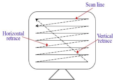
The electron beam in raster scan sweeps from top to bottom by covering one row at a time.
The beam is intensity on and off is creating the pattern of illuminated pattern of spots as it moves from each row.
The memory area is known as refresh buffer or frame buffer as it stores picture definition.
The memory area holds intensity values for all screen points.
The figure 1.1.3 shows the representation of scan line, vertical retrace and horizontal retrace in raster scan display.
Fig. no.1.1.3 |
1.1.4 Basic Display Processor
The display device is an output device which is used to represent the information in the form of images.
It is also known as the video monitor or video display unit (VDU).
These devices are designed to display, view, model or display information.
The main advantage of displaying is the sharing of information.
There are some display devices given below.
- Cathode-ray tube (CRT)
- Color CRT monitor
- Light emitting diode (LED)
- Liquid crystal display (LCD)
- Direct view storage tubes (DVST)
- Plasma display
- 3D display
The output image that describes by the series of graphics command is known as display list or display file.
The various primitives get combines to execute image creation.
The process is executed by specialized display or completely independent system CPU.
The display file is represented in 2D and 3D dimensional space.
The scene is stored by display list called as retained mode.
Atari 8-bit family is the one of the earliest popular display list.
It is also known as Atari terminology.
It is a series of instruction for ANTIC as video processor.
Scan Conversion:
Scan conversion it digitization process where picture definition is given to the application program into set of pixels intensity values for storage in the frame buffer.
Lines and Line Segments:
The line is defined by points and the points are specified by pair of numbers (x,y).
Here, x represents horizontal distance and y represents the vertical distance.
The lines can be extended by both the forward and backward direction.
Vectors and Vector Generation:
The vector having single direction and length.
It is denoted by (dx,dy) where dx indicates the x axis direction and dy indicates y axis direction..
DDA Line drawing algorithm
Digital differential analyzer (DDA) is the simple line generation algorithm.
Line connects two points.
Hence to draw any line we need at least two points.
Hence, we prefer one point as (X1, Y1) and second point is (X2, Y2).
Following are some steps to perform DDA algorithm.
Step 1: Get the input (X1, Y1) and (X2, Y2) Step 2: calculate the slope of the line using inputs. M= Y2-Y1/X2-X1 Step 3: according to slope of the line we need to decide the case which gives the next point of line. Following are three cases are used to solve the DDA algorithm. Case 1: m<1 Xn=X1+1 and Yn=Y1+m Case 2: m>1 Xn=X1+1/m and Yn=Y1+1 Case 3: m=1 Xn=X1+1 and Yn=Y1+1 Step 4: the process continues till we get the input point (X2, Y2). Then the line generates with the help of coordinates that we occur. Example: Inputs: (X1, Y1) = (0,0) and (X2, Y2) = (8,4) M= Y2-Y1/X2-X1 M=4-0/8-0 M = 0.5 Here M=0.5 |
Hence follow case 1 where M<1 then Xn=X1+1 and Yn=Y1+m
X1 | Y1 | Xn | Yn |
0 | 0 | 0 | 0 |
0+1=1 | 0+0.5=0.5 | 1 | 1 |
1+1=2 | 0.5+0.5=1 | 2 | 1 |
2+1=3 | 1+0.5=1.5 | 3 | 2 |
3+1=4 | 1.5+0.5=2 | 4 | 2 |
4+1=5 | 2+0.5=2.5 | 5 | 3 |
5+1=6 | 2.5+0.5=3 | 6 | 3 |
6+1=7 | 3+0.5=3.5 | 7 | 4 |
7+1=8 | 3.5+0.5=4 | 8 | 4 |
At last, we get the last point (X2, Y2) = (8,4) we stop.
Summary:
The DDA circle drawing algorithm has four steps. Step 1: Get the input (X1, Y1) and (X2, Y2) Step 2: calculate the slope of the line using inputs. M= Y2-Y1/X2-X1 Step 3: according to slope of the line we need to decide the case which gives the next point of line. Following are three cases are used to solve the DDA algorithm. Case 1: m<1 Xn=X1+1 and Yn=Y1+m Case 2: m>1 Xn=X1+1/m and Yn=Y1+1 Case 3: m=1 Xn=X1+1 and Yn=Y1+1 Step 4: the process continues till we get the input point (X2, Y2). Then the line generates with the help of coordinates that we occur. |
Bresenham Line drawing algorithm
It is another line generation algorithm known as incremental scan conversion algorithm. It uses only integer calculations. Following are steps to perform bresenham’s algorithm. Step 1: Get the input (X1, Y1) and (X2, Y2) Step 2: Find decision parameter Pk and P0 Pk=2 ∆Y - ∆X Where ∆X=X2-X1 and ∆Y=Y2-Y1 Step 3: according to the value of Pk we need to decide the case which gives the next point of line. Following are three cases are used to solve the bresenham’s algorithm. Case 1: Pk>0, Pk+1=Pk + 2 ∆Y - 2 ∆X Where Xn=X1+1 and Yn=Y1+1 Case 2: Pk<0, Pk+1=Pk + 2 ∆Y Where Xn=X1+1 and Yn=Y1+1 Step 4: the process continues till we get the input point (X2, Y2). Then the line generates with the help of coordinates that we occur. Example: Step 1: Get the input (X1, Y1) and (X2, Y2) (X1, Y1) = (20,10) and (X2, Y2) = (30,18) Step 2: find decision parameter Pk and P0 Pk=2 ∆Y - ∆X Where ∆X=X2-X1=30-20=10 and ∆Y=Y2-Y1=18-10=8 Hence, Pk=2 ∆Y - ∆X = 2*8-10= 16-10=6 |
Pk | Xn | Yn |
>0 | 21 | 11 |
2>0 | 22 | 12 |
-2<0 | 23 | 12 |
14>0 | 24 | 13 |
10>0 | 25 | 14 |
6>0 | 26 | 15 |
2>0 | 27 | 16 |
-2<0 | 28 | 16 |
14>0 | 29 | 17 |
10>0 | 30 | 18 |
At last, we get the last point (X2, Y2) = (30,18) we stop. Summary: Bresenham’s line drawing has following four steps. Step 1: Get the input (X1, Y1) and (X2, Y2) Step 2: Find decision parameter Pk and P0 Pk=2 ∆Y - ∆X Where ∆X=X2-X1 and ∆Y=Y2-Y1 Step 3: according to the value of Pk we need to decide the case which gives the next point of line. Following are three cases are used to solve the bresenham’s algorithm. Case 1: Pk>0, Pk+1=Pk + 2 ∆Y - 2 ∆X Where Xn=X1+1 and Yn=Y1+1 Case 2: Pk<0, Pk+1=Pk + 2 ∆Y Where Xn=X1+1 and Yn=Y1+1 Step 4: the process continues till we get the input point (X2, Y2). Then the line generates with the help of coordinates that we occur. |
DDA
This algorithm uses the incremental method to draw each point. The algorithm calculates the starting point and by the value of E the value of x and y coordinates will be increases and decreases respt. The equation of circle is r2=X2+Y2 To calculate the value of E, We have formula, 2n-1<=r <=2n where r = radius of circle E=2^-n=1/2^n E is used to calculate the value of circle point which helps to draw a circle as X2=X1+E Y1 for x and Y2=Y1- E X2 for y Algorithm: Step 1: Read the radius r of the circle and calculate value of E Step 2: Start X=0 i.e. initial point and Start Y=r i.e. radius Step 3: X1=0 and Y1=r Step 4: Do { X2=X1+E Y1 Y2=Y1-E X2 //Here X2 represents Xn+1 and X1 represent Xn //Xn is from equation of circle Plot (int X2,int Y2) //here swapping points to calculate next closest pixel X1=X2 Y1=Y2 } While ((Y1-Y0)< E or (X0-X1)>E) //here while condition is to check the current position is starting point or not, if current point is not starting point then repeats. Step 5: stop Summary: In DDA circle drawing algorithm the radius and initial points are taken. Value of E is calculated by given radius. The value of X2 and Y2 are calculated by given formula and pot them. X2=X1+E Y1 Y2=Y1-E X2 The next points are then calculated by swapping points as X1 with X2 and Y1 with Y2. |
Bresenham
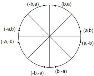
Following circle shows in figure 1.5.2 the 8 portions from which we will occur the coordinates of circle.
Fig. no. 1.5.2 |
Algorithm:
Step 1: input of circle radius r, (Xc, Yc) Step 2: initial value X=0 and Y=r Step 3: plot pixel (X+Xc, Y+Yc) Step 4: decision parameter Pk=3-2r Step 5: start of loop If Case 1: If Pk<0 then Pk+1=Pk+4X+6 Where Xn=X+1 and Yn=Y Else Case 2: If Pk>0 then Pk+1=Pk+4(X-Y) +10 Xn=X+1 and Yn=Y-1 Step 6: X=Y stop Example: Given R=10 Hence Y=R If we want to draw circle in center then we have given the center points as (Xc, Yc) = (2,2) Decision parameters are Pk and P0. P0=3-2r Here, P0=3-2*10=3-20=-17 Hence Pk=P0= -17 Following are two cases that will be decided according to Pk’s value. Case 1: If Pk<0 then Pk+1=Pk+4X+6 Where Xn=X+1 and Yn=Y Case 2: If Pk>0 then Pk+1=Pk+4(X-Y) +10 Xn=X+1 and Yn=Y-1 |
Pk | Xn | Yn |
-17<0 | 0 | 10 |
-17+4*1+6=-7<0 | 1 | 10 |
-7+4*2+6=7>0 | 2 | 10 |
7+4*(3-9)+10=-7<0 | 3 | 9 |
-7+4*4+6=15>0 | 4 | 9 |
15+4*5-4*8+10=-7<0 | 5 | 8 |
-7+4*6+6=23>0 | 6 | 8 |
| 7 | 7 |
Here X=Y then stop
Summary:
We only need to calculate the values on to border of the circle in the first octant. The other values may be determined by symmetry. It has 5 steps. Step 1: input of circle radius r, (Xc, Yc) Step 2: initial value X=0 and Y=r Step 3: plot pixel (X+Xc, Y+Yc) Step 4: decision parameter Pk=3-2r Step 5: start of loop |
Stroke Principle
It uses small line segments to generate character.
The small series of segment are drawn like stroke of pen to form a character.
The line drawing algorithm can also be used in stroke method.
Starburst Principle
The line segments having fix pattern used to generate character.
Segments are required to display for particular character are highlighted out of 24-line segments.
This method appears as characteristic appearance so it is called as starburst method.
24 bits are required to represent a character.
In this method the character quality is poor.
Bitmap Method
It is also referred as dot matrix method.
The characters are represented as array of dots in the matrix form.
The matrices having two columns and rows.
An 5*7 array is used commonly to represent character.
Each dot matrix is a pixel.
The character is placed on screen by copying pixel values from the character array into some portion of the screen’s frame buffer.
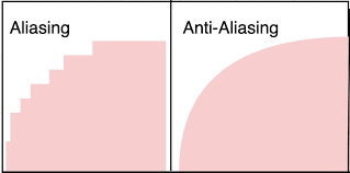
If the resolution is too low, visual stair stepping of edges that occur in an image is aliasing.
Antialiasing is smoothing of jagged edges in digital images by averaging the colors of the pixels at boundary.
Following figure 1.7 shows the difference between aliasing and antialiasing.
|
Fig. no. 1.7
References
- S. Harrington, “Computer Graphics” ‖, 2nd Edition, McGraw-Hill Publications, 1987, ISBN 0 – 07– 100472 – 6.
- Donald D. Hearn and Baker, “Computer Graphics with OpenGL”, 4th Edition, ISBN-13:9780136053583.
- D. Rogers, “Procedural Elements for Computer Graphics”, 2nd Edition, Tata McGraw-Hill Publication, 2001, ISBN 0 – 07 – 047371 – 4.
- J. Foley, V. Dam, S. Feiner, J. Hughes, “Computer Graphics Principles and Practice” ‖, 2nd Edition, Pearson Education, 2003, ISBN 81 – 7808 – 038 – 9.
- D. Rogers, J. Adams, “Mathematical Elements for Computer Graphics” ‖, 2nd Edition, Tata McGraw Hill Publication, 2002, ISBN 0 – 07 – 048677 – 8.


