Unit 3
Windowing, Clipping, 3D Transformations and Projections
3.1.1 Concept of Window and Viewport
The portion of screen where the selection and enlarging the portion of drawing method is used is called as windowing.
The world coordinates are used to select window.
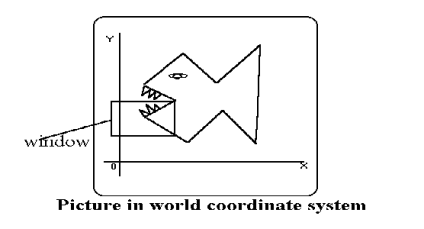
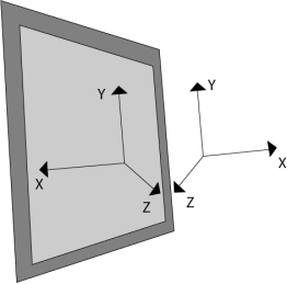
The window as shown in figure 3.1 becomes an imaginary box where we select objects or enclose the area of the object.
The size of window is (0,0) coordinates which is bottom left corner and towards the right side until the window encloses the desired area.
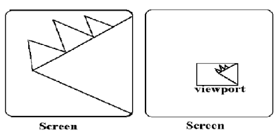
The area on display device where the window is mapped is called as viewport.
|
Fig. no. 3.1
The viewport is a section of screen where the images are encloses by the window on the world coordinate system will be drawn.
When a window is placed on the object and parts of the objects can be seen.
The points and the lines that are outside the window are cut off from view.
This process of cutting off parts of the image on the screen is called as clipping.
In clipping we examine the object with each line that comes completely inside the window, completely outside the window or crosses the window.
If the lines are inside the window then lines will be displayed, if the lines or points are completely outside the window then it is not displayed.
If the line and the points are crossing the window then the part of intersection will be taken and the portion which comes inside the window that will be displayed other part will be not displayed.
Below figure 3.1 (a) shows the clipping process.
|
Fig. no. 3.1 (a)
3.1.2 Viewing Transformations
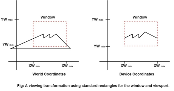
The viewing transformation is the mapping part of the world coordinate scene to device coordinate.
The viewing transformation is also called as the window to viewport transformation or windowing transformation.
Following figure 3.1 (b) shows the viewing transformation using standard rectangle for window and viewport.
|
Fig. no. 3.1 (b)
Following are some steps to perform viewing transformation:
- First we construct the scene in the world coordinate system using the primitives and attributes.
- To obtain the particular orientation, set up a 2D viewing coordinate system in the window coordinates plane and define a window in a viewing coordinates system.
- After viewing frame established the transformation description comes at world coordinates to view coordinates.
- Define viewport in normalized coordinates.
- Map the viewing coordinates description of the scene to normalized coordinates.
Finally, all the parts of the picture are enclosed in the device coordinates.
3.2.1 Cohen Sutherland Method of Line Clipping
The line clipping is same as the point clipping method.
The line that is outside the window is cut and the line which is inside the window that will be displayed.
This algorithm uses the line clipping method.
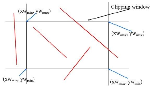
The minimum coordinates for the clipping region is (XWmin, YWmin) and the maximum coordinates are (XWmax, YWmax).
As below figure 3.2 shows the concept of cohen Sutherland line clipping.
|
Fig. no. 3.2
There are three possibilities for line as-
- The line which is completely inside the window will be accepted.
- The line which is completely outside the window will be discarded.
- The line which is partially inside the window in that the portion which is inside that will be shown and other part will be discarded.
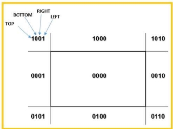
The 4bits are used to divide the entire region.
These 4 bits represents the top, bottom, top and left as the figure 3.2 (a) shows.
|
Fig. no. 3.2 (a)
Following are steps to perform the cohen Sutherland algorithm which are based on 4 bits that are given above.
- Assign a region code for each endpoints.
- If both endpoints having bits 0000 then that line will be accepted.
- Else perform logical AND operation on the region code.
- If the result is not 0000 then reject line.
- Else need clipping process
- Choose an endpoints of the line that is outside the window.
- Find the intersection point at the window boundary.
- Replace the endpoints with that intersection points and update the region code.
- Repeat step 2 until we get the clipped line either trivially accepted or trivially rejected.
Repeat step 1 for other lines.
3.3.1 Sutherland Hodgeman Method for Convex and Concave Polygon Clipping
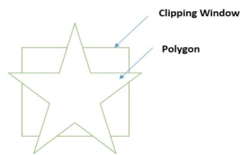
The Sutherland Hodgeman polygon clipping algorithm is used for polygon clipping.
The polygon can also be clipped by specifying the clipping window.
All the vertices of the polygon are clipped against each edge of the clipping window.
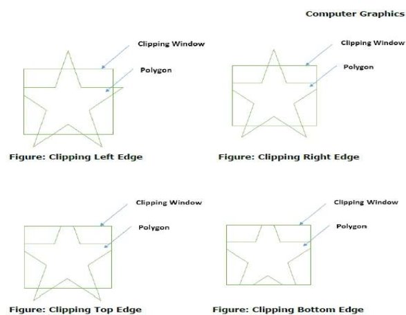
First the polygon is clipped against the left edge of the polygon window to get new vertices of the polygon.
The new vertices are used to clip the polygon against right, top and bottom edge.
While processing an edge of a polygon with clipping window, an intersection point is found if edge is not completely inside the clipping window and the partial edge from the intersection point to the outside edge is clipped.
Following figure 3.3 (a) and 3.3 (b) shows the Sutherland Hodgeman polygon clipping algorithm.
|
Fig. no. 3.3 (a)
|
Fig. no. 3.3 (b)
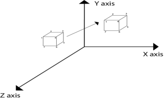
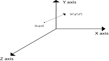
The translation is used for moving object from one position to another position like in 2D.
There are three vectors in 3D to be changed for translation process as x, y, z axis. In 3D there are also the three translation vectors used. The translation in x direction represented as tx, in y-direction ty and in z direction it is represented as tz. If P (x, y, z) is the point which is going to be translated with the translation vectors (tx, ty, tz) then new vectors will be, X’=X+tx Y’=Y+ty Z’=Z+tz Following is the matrix for translation:
or
X’ 1 0 0 tx X Y’ = 0 1 0 ty Y Z’ 0 0 1 tz Z 1 0 0 0 1 1
Following figure 3.1.1 shows the translation process in 3D:
Fig. no. 3.1.1
|
Summary:
The translation process is used in 2D and 3D space.
This process is used to translate the object from one axis to other in 3D.
In process the X’, Y’ and Z’.
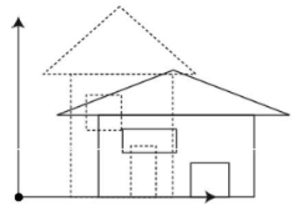
It is used to change the size of object like 2D transformation. The size can be increased or decreased by using scaling. If the scaling vectors are same or equal i.e. Sx=Sy=Sz then it is known as uniform scaling. If the scaling vectors are different then it is known as differential scaling. In 3D there are three scaling factors as Sx, Sy and Sz. Sx for x direction, Sy for y direction and Sz for z direction.
Sx 0 0 0 0 Sy 0 0 0 0 Sz 0 0 0 0 1 It is mathematically represented as, P’=P * S
0 Sy 0 0 0 0 Sz 0 0 0 0 1 = [X. Sx Y. Sy Z. Sz 1] Steps for scaling the object if the object is located at the fixed place.
Following figure 3.1.2 shows the scaling in 3D transformation.
Fig. no. 3.1.2 |
Summary:
The scaling transformation required three steps.
Translate
Scale
Retranslate
3.4.3 Rotation About X, Y, Z & Arbitrary Axis
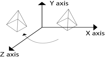
It is used to rotate an object about an angle.
The object can be rotate anticlockwise or clockwise.
This rotation is complex than the 2D rotation.
In this the axis are also important with the angle of rotation.
The axis can be x, y or z.
Following figure 3.1.3 shows the rotation about y axis:
|
Fig. no.3.1.3
Rotation matrix are represented as:
Rx(Ꙫ)=
Ry (Ꙫ)=
Rz (Ꙫ)=
|
Summary:
The rotation transformation has x, y, z axis to perform the rotation.
It has 3 matrices for each axis of rotation.
3.4.4 Rotation about an Arbitrary Axis
The rotation about an axis is used when the object is rotated about an axis at that time it is not parallel to axis.
In rotation of object, it needs to be parallel to the one of the axes.
Hence the addition transformation is required.
First, it adjusts the alignment of the object and then it translates the object back to the original position.
Following are the steps required to solve the rotation about an arbitrary axis.
- Translate the object to the origin
- Rotate the object from which the object will comes under any of the coordinate axis.
- Perform rotation on the object with the coinciding axis.
- Apply reverse rotation to bring the object back to the original coordinates.
- Apply reverse translation to bring rotation axis to the original position
Example:
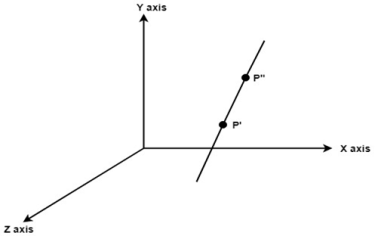
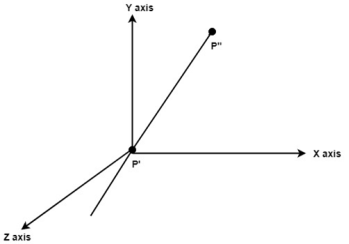
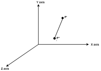
Following figure shows the initial position of P’ and P’’.
|
Fig. no.3.1.4 (a)
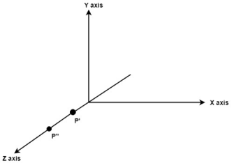
Translate object P’ to origin
|
Fig. no. 3.1.4(b)
Rotate P’’ to z axis so that it aligns along the z axis
|
Fig. no.3.1.4(c)
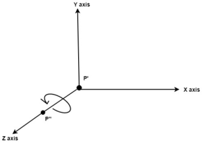
Rotate about around z axis
|
Fig. no. 3.1.4(d)
Rotate axis to the original position
|
Fig. no. 3.1.4(e)
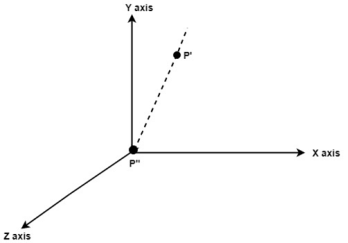
Translate axis to the original position
|
Fig. no. 3.1.4(f)
Summary:
Following steps are used in rotation about an arbitrary axis.
- Translate the object to the origin
- Rotate the object from which the object will comes under any of the coordinate axis.
- Perform rotation on the object with the coinciding axis.
- Apply reverse rotation to bring the object back to the original coordinates.
- Apply reverse translation to bring rotation axis to the original position
3.4.5 Reflection about XY, YZ, XZ & Arbitrary Plane
it is a mirror image of object.
The reflection axis and the reflection plane is selected for this process.
3D reflections are same as 2D reflections.
Reflection is occurred on 180 degree about the given axis.
The reflection can be done on xy, yz or xz axis.
Following figure 3.1.5 shows the reflection on axeses.
|
Fig. no. 3.1.5
Following are the reflection matrices used for three planes.
Reflection about XY plane,
1 | 0 | 0 | 0 |
0 | 1 | 0 | 0 |
0 | 0 | -1 | 0 |
0 | 0 | 0 | 1 |
Reflection about YZ plane,
-1 | 0 | 0 | 0 |
0 | 1 | 0 | 0 |
0 | 0 | 1 | 0 |
0 | 0 | 0 | 1 |
Reflection about XZ plane,
1 | 0 | 0 | 0 |
0 | -1 | 0 | 0 |
0 | 0 | 1 | 0 |
0 | 0 | 0 | 1 |
Summary:
Reflection is the mirror image of object in which the reflection axis and reflection plane is selected.
All the axis has its matrices for calculation.
In 2D, X and Y coordinates are used but in 3D the extra z coordinate is added.
The 3D computer graphics and its applications are applied in computer games, entertainment, etc.
It is also used in scientific visualization
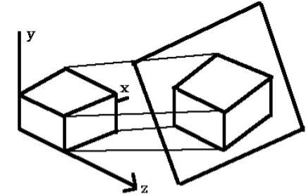
Following are the types of projection.
Oblique – Cavalier, Cabinet, Orthographic – Isometric, Diametric, Trimetric
The parallel projection discards the z coordinate.
The parallel line from each vertex on the object are extended until they intersect the view plane.
The direction of the projection will be specified instead of center of projection.
The distance between project plane and the center of the projection is infinite, in parallel projection.
In parallel projection the projected vertices are connected to the original object by line segments.
This projection is good for exact measurement but not so realistic.
There two measure types of projection as follows:
- Oblique projection
- Orthographic projection
Oblique Parallel Projection
The projection of the plane and the direction of the projection is not normal in oblique projection.
The object can be view better in oblique projection than orthographic projection.
There are two types in oblique projection as follows:
- Cavalier
- Cabinet
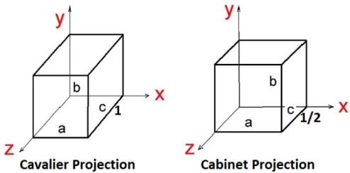
Cavalier Projection:
The cavalier makes the angle 45 to the projection plane.
In cavalier the projection line is perpendicular to the view plane with same length as the line itself.
The foreshortening factors for all three principal directions are equal.
Cabinet Projection:
The cabinet makes the angle 63.4 to the projection plane.
In cabinet the projection line is perpendicular to the view plane surface with 1/2 length as the line itself.
Both the projections are as follows in figure 3.2.1.
|
Fig. no. 3.2.1
Orthographic Projection
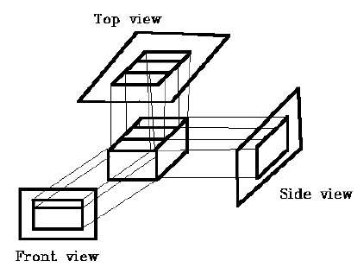
In orthographic projection the direction of the projection is normal to the projection of the plane.
There are three types of the orthographic projections:
- Front projection
- Top projection
- Side projection
Following figure 3.2.1 (a) shows the orthographic projection.
|
Fig. no. 3.2.1(a)
Isometric Projection:
The object that shows the more than one side of the object in orthographic projection then it is known as axonometric orthographic projections.
The isometric projection is the most common axonometric projection.
The projection plane intersects each coordinate axis in the model coordinate system at an equal distance.
The angles of projection are not preserved but parallelism of projections is preserved.
Following figure 3.2.2 shows the isometric projection:
|
Fig. no. 3.2.2
Diameter Projection:
In diameter projection, two of the three axes of space appear foreshortened.
The direction of viewing is equally foreshortened.
Based on angle of viewing the attendant scale and angles of presentation are determined.
The scale of the third direction is determined separately.
The dimensional approximation is common in diametric projection.
Trimetric Projection:
In diameter projection, all three axes of space appear foreshortened.
The direction of viewing is unequally foreshortened.
Based on angle of viewing the attendant scale of three axes and angles of presentation are determined.
The dimensional approximation is common in trimetric projection.
The trimetric perspective is used in trimetric drawings.
Vanishing Points as 1 Point, 2 Point And 3 Point
The distance between center of the projection and project plane is finite in perspective projection.
The distance looks realistic in perspective projection.
The size of the object varies inversely with distance.
The parallelism is not maintained as well as the distance and angles are not preserved in perspective projection.
Distance, angles and the lines converge at the center of the projection or projection reference point.
There are three types of points in the perspective projection as given below:
- One point: it is simple to draw
- Two point: it gives better impression of depth.
- Three point: it is difficult to draw.
References
- S. Harrington, “Computer Graphics” ‖, 2nd Edition, McGraw-Hill Publications, 1987, ISBN 0 – 07– 100472 – 6.
- Donald D. Hearn and Baker, “Computer Graphics with OpenGL”, 4th Edition, ISBN-13:9780136053583.
- D. Rogers, “Procedural Elements for Computer Graphics”, 2nd Edition, Tata McGraw-Hill Publication, 2001, ISBN 0 – 07 – 047371 – 4.
- J. Foley, V. Dam, S. Feiner, J. Hughes, “Computer Graphics Principles and Practice” ‖, 2nd Edition, Pearson Education, 2003, ISBN 81 – 7808 – 038 – 9.
- D. Rogers, J. Adams, “Mathematical Elements for Computer Graphics” ‖, 2nd Edition, Tata McGraw Hill Publication, 2002, ISBN 0 – 07 – 048677 – 8.
