Unit 5
Curves, Fractals and Animation
5.1.1 Introduction
A curve is an infinite large set of points.
Each point has two neighbors except endpoints.
The classification of the curve is as follows:
- Explicit curve
- Implicit curve
- Parametric curve
5.1.2 Interpolation and Approximation
The interpolation is filling in frames between the key frames.
It uses the polynomial interpolation to draw images semi automatically.
It is a generating principle which enables to model connected curve segments from the discrete ordered sets of points in the extended space.
5.1.3 Spline interpolation methods- Hermite interpolation
It is a polynomial unction that is used for interpolating data points.
The Hermite interpolating polynomial is same as newton interpolating polynomial.
The interpolating polynomials are calculated by divided differences.
The Hermite interpolation can be calculated without using divided differences.
The observed value can be unknown to the Hermite interpolation.
Hermite interpolation
It is a polynomial unction that is used for interpolating data points.
The Hermite interpolating polynomial is same as newton interpolating polynomial.
The interpolating polynomials are calculated by divided differences.
The Hermite interpolation can be calculated without using divided differences.
The observed value can be unknown to the Hermite interpolation.
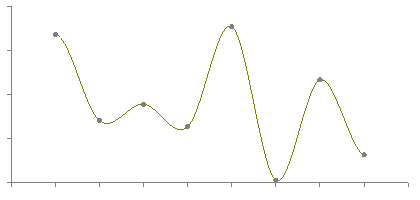
Following figure 6.1.3 (b) shows the representation of the Hermite interpolation.
|
Fig. no. 6.1.3 (b)
Summary:
The interpolation is filling in frames between the key frames.
The interpolating algorithms are as follows:
- Hermite interpolation
- Linear interpolation
- Cubic interpolation
5.1.4 B-Spline Curve
B-spline curve overcomes the limitation of Bezier curve as Bezier curve has limited flexibility. It is a special case of Berstein basis. It is non-global method. It consists of linear combination of control points Pi and B-spline basis function Ni. The mathematical representation of B-spline curve is, C(t) = ∑ Pi * N (i, k) (t) Where summation limitation is n to i=0 and n >= k-1, t belongs to (tk - 1, tn + 1) Here k is order of polynomial segments of B-spline curve. N(i,k)(t) it is an normalized B-spline blending function. Following figure 6.1.5 shows the B-spline curve.
Fig. no. 6.1.5 |
Properties of B-spline curve:
- The sum of B-spline basis function for any parameter value is 1.
- For all parameter values each basis function is positive or 0.
- Each basis function have one maximum value except for k=1.
- The number of vertices in polygon is equal to the maximum order of the curve.
- The degree of B-spline polynomial is independent on the number of vertices of polygon.
- B-spline curve allows the local control over the curve surface.
- It explicit the variation diminishing property.
- It follows the shape of the defining polygon.
Summary:
B-spline curve overcomes the limitation of Bezier curve as Bezier curve has limited flexibility.
It is a special case of Berstein basis.
The mathematical representation of B-spline curve is,
C(t) = ∑ Pi * N (i, k) (t)
5.1.5 Bezier Curve
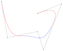
The Bezier curve are developed by French engineer Pierre Bezier. The Bezier curve is generated under the control of other points. To generate the Bezier curve approximate tangents are used by using control points. The mathematical representation of Bezier curve is, ∑ Pi * B ni (t) where summation from n to k=0 Pi is the set of points and B(t) is berstein polynomials as B(t)= (n, i) (1 - t) n-I * ti The simple beizer curve is a straight line from P0 to P1. A quadratic Bezier curve has three control points. A cubic Bezier curve is determined by four control points. Following figure 6.1.6 represents the Bezier curve.
|
Fig. no. 6.1.6
Properties of Bezier curve:
- It follows the shape of the control polygon which consist of segment joiing the control points.
- It always passes through first and last control point.
- The convex hull contains the Bezier curve with defining control point.
- The degree of the polynomial defining the curve segment is 1 less.
The Bezier curve follows the polynomial control points.
Summary:
The Bezier curve are developed by French engineer Pierre Bezier.
The Bezier curve is generated under the control of other points.
The mathematical representation of Bezier curve is,
∑ Pi * B ni (t) where summation from n to k=0
5.2.1 Introduction
The fragmented geometric shape that can be split into parts.
Fractal is the complex picture that is generated by computer from one formula.
Fractals are created using iteration.
The formula of fractal repeats again and again with slightly different values.
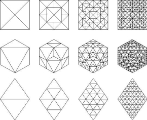
The figure 6.1.7 represents as different shapes of fractals.
|
Fig. no. 6.1.7
5.2.2 Classification of Fractals
The fractals can be classified as:
Self-Similar Fractal:
These fractals are scaled down the version of entire object.
The overall fractals are scaled by the applying the scaling parameter s to the initial shape.
It is all over the user to choose the same scaling factor s for all subparts or different scaling factors for different scaled down parts.
In sub class of self-similar fractal, the user can use the random variation to the scaled down sub parts.
These fractals are used to model tree, shrubs and other plants.
Self-Affine Fractal:
The self-affine fractals are scaled down with different scaling parameters as Sx, Sy and Sz in different coordinate direction.
We can apply random variations to obtain self-affine fractals.
These fractals are used to model water, clouds and terrain.
Invariant:
The invariant fractals uses the non-linear transformation.
It includes self-squaring function such as Mandelbrot set.
It uses inversion procedure to form squaring function and self-inverse fractals.
Summary:
The fractals are classified as:
- Self-Similar Fractal
- Self-Affine Fractal
- Invariant
5.2.3 Fractal Dimension
As the scale changes the ratio of change in detail by the quantifying complexity.
The index for characterizing fractal patterns are known as fractal dimension.
The fractal dimensions can be count as empirically and theoretically.
The categorization a broad spectrum of objects ranging from the abstract.
It is a practical phenomenon.
5.2.4 Fractal Dimension and Surfaces
It is a measure of fractal dimension of surface geometric complexity.
It can take any non-integer value between 2 and 3.
Normally the dimension of surface is 2.
The fractal dimension get increase with its greater amount of complexity or roughness.
5.2.5 Hilbert Curve
It is also known as Hilbert space filling curve.
It is continuous fractal space filling curve.
It is developed by German mathematician David Hilbert.
As it is a space filling algorithm its Hausdroff dimension is 2.
It has unit square image which has dimension as 2.
Its graph is compact set homeomorphism to the closest interval.
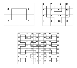
Following figure 6.1.7 (a) shows the Hilbert curve.
|
Fig. no. 6.1.7 (a)
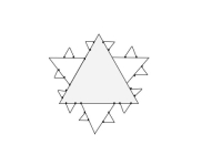
5.2.6 Koch curve
It is known as Snowflake curve.
The meaning of Koch curve is Koch star or Koch island.
It is mathematical curve and described earliest than the other fractals.
Following are some step to create snowflake fractal.
Step 1: draw a triangle.
Step 2: divide each side in three equal parts.
Step 3: draw an equilateral triangles on each middle part.
Step 4: divide each outer side into three and second generation of triangles covers the bit of first.
Step 5: repeat the process to get the snowflake fractal.
Following figure 6.1.7 (b) shows the snowflake fractal.
|
Fig. no. 6.1.7 (b)
5.3.1 Basics of animation
Animation is the movement on the screen of the display device.
Animation means giving life to any object in graphics.
It is created by displaying a sequence of still images.
Animation is the technique of designing, drawing, making layout and preparation of photographic series that are integrated to create a multimedia and games.
It connects the exploitation and the management of still images to generate the illusion of movement.
A person who creates the animation is called animator.
5.3.2 Types of animation
Conventional and Computer Based Animation
Conventional Animation:
The conventional model has unlimited technology and computing techniques.
It is faster than computer animation for high quality.
The complete control of drawing and motion in conventional animation.
The conventional animation is limited by artistic ability.
Computer Animation:
In computer animation many frames can be calculated instead of drawing.
Many variations can be tried quickly in computer.
The complex 3D models are easy to draw in computer animation as in this don’t have to draw different views.
In computer animation there are fewer tedious steps.
Summary:
There are two types of animation.
Computer animation- many frames can be calculated instead of drawing.
Conventional animation- unlimited technology and computing techniques.
5.3.3 Principles of animation
Following some principles are introduce by Disney animators.
- Squash and stretch
It is use to give weightage and flexibitity to drawn object.
It is applicable to the simple and complex objects such as bouncing ball or musculature human face.
- Anticipation
It is use to make the action more realistic by using audience for action.
For example. If a dancer is jumping on the floor then the dancer has to bend knees first.
- Staging
This is also known as theater and film.
It is used to direct the direction of audience and shown them the importance of the scene clearly.
This can be done by using various use of light and shadows, character in the frame or angle and position of the camera.
- Straight ahead action and pose to pose
There are two processes to draw object as follows:
Straight ahead action: the animation starts from beginning and animated frame by frame till end.
Pose to pose: it starts from beginning and draw few key frame and filling them in intervals.
The combination of straight ahead action and pose to pose both are used mostly.
- Follow through and overlapping action
This technique is use for two closely related movements which makes movement more realistic.
This principle gives impression on objects that character follows the physics laws which includes principle of inertia.
- Slow in and slow out
The object is accelerated from beginning to end.
As human body, animals, vehicles, etc. needs some time to accelerate and slow down.
The slow in and slow down effect shows more realistic movement of acceleration.
5.3.4 Design of Animation Sequences
Following are some steps of designing the animation sequences.
1. Layout of Storyboard
It is an action layout that is used to illustrate the motion sequence as a set of basic events which are to acquire place.
It is an animation that selects the storyboard layout.
Hence the storyboard layout comprises the set of rough sketches.
2. Definition of Object
The definition of object is applied on all the participant objects in action.
The objects can be treated as fundamental shapes or related to movement with shapes.
3. Specification of Key Frame
It is detailed drawing of the scene at an exact time in the animation sequence.
In each key frame all objects are positioned according to time for that frame.
In the action several key frames are used at the extreme positions and other keys are spaced.
Hence the time interval of key frame is not great.
More key frame is given for intricate motion than for easy and slowly varying motions.
4. In Between Frames Generation
The in-among frames are the frames are the middle frame in key frames.
Most of the among frames are based on the media that are utilized to display animation.
Commonly the 24 frames are needed per second and graphic terminal are refreshed on the rate of 30 to 60 frames per second.
The time interval for the motion is set up and therefore 3 to 5 among for each pair of key frames.
Several key frames can be duplicated by identified the speed for motion.
Summary:
The animation sequences are as follows.
1. Layout of Storyboard
2. Definition of Object
3. Specification of Key Frame
4. In Between Frames Generation
5.3.5 Animation Languages
The animation sequences are handled with the set of animation routines.
Following are some languages that are used as animation languages.
- C
- Lisp
- Pascal
- FORTRAN
Several animation languages have been developed.
The animation functions are used as graphics editor, key frame generator, in-between generator and standard graphic routines.
The graphic editor is used to design and modify object shapes using spline surfaces, constructive solid geometry methods or other representation.
5.3.6 Key Frame Systems
The changes in animation will be defined by key framing.
In animation every frame is the key frame which is created frame by frame.
In 3D animation the exact position of the given object is not specify on every single frame.
For specifying this position, they create key frames.
Key frame is important for changing size, shape or the other properties of the object in animation.
The computer then search out all the in-between frames and saves an extreme amount of time for animator.
Following figure 5.2.3 shows the key frames that are created by computer and user.
Fig. no. 5.2.3 |
5.3.7 Morphing
The transformation of the object from one form to another form is called as morphing.
It most complicated transformation.
It is shortened from the metamorphosis.
It looks like the two images are mixed into each other as fluid mixes.
In technical terms the images are distorted and fade occurs between them.
The morphing can be applied on any of the motion that changes the shape.
5.3.8 Motion Specification
In animation the motion can be expressed in various terms.
Direct Motion Specification:
It is a straight forward method to define a motion.
In this rotation angles and translation vectors are given explicitly.
The matrices are used to translate the position of coordinates.
It is a simple method used by simple user programmed animation sequences.
Goal Directed System:
The motion which describes the action in animation is defined by the goal directed system.
It specifies the motion parameters which have given the goal of the animation.
For example, if we want to move an object from one position to destination, we use goal directed system.
The components motion will be interpreted as a accomplished selected task in goal directed system.
Kinematics and Dynamics:
Kinematics and the dynamics are also used to construct animation sequences.
In kinematics the motion parameters positions, velocity and without references force which causes the motion are specified.
For constant velocity the motion of rigid bodies is designated by giving initial position and velocity vector for each object.
In dynamics the specification of forces is required which produces the velocities and acceleration.
Summary:
The motion specification has three different terms to express as:
Direct Motion Specification
Goal Directed System
Kinematics and Dynamics
5.3.9 Methods of Controlling Animation
Following are methods of controlling animation.
Explicitly declared control
The transformation that specified by object to object.
The frame level by specifying key frames and methods for interpolating between them.
Procedural control
It is based on communication among different objects.
Each object having knowledge about static or dynamic properties of other objects.
It can be used to ensure consistency.
Constraint based control
In constraint-based control, many objects movement in the real world are determined by other objects which they come in contact.
The object motion can be control by environment-based constraint.
Analyzing live action-based control
The examining the motion of object in the real world is achieved by the control.
The animated movies use the frame-by-frame method to trace the live action movement.
Kinematics and dynamic control
It refers to the velocity and position of points.
Dynamics takes into account the physical laws that governs kinematics.
5.3.10 Frame-By-Frame Animation Technique
The changes are made in every key frame to create the illusion of movement.
It increases the file size rapidly because it has to store each key frame.
It is tedious to do on hand drawn cel animation where each drawing should present on each sheet paper.
5.3.11 Real-Time Animation Techniques
It is also known as real time capture or lice animation.
It is a process of using motion capture system to puppet a 3D character lives in real time.
Previsualization uses the real time animation technique so the director can see the actor is performing mocap actor’s animation.
It allows to present at game cons, appear on talk shows, and speak at keynotes. It has ability to bring 3D characters to life.
Summary:
The animation can be control in various form as:
- Explicitly declared control
- Procedural control
- Constraint based control
- Analyzing live action-based control
- Kinematics and dynamic control
- Frame-By-Frame Animation Technique
- Real-Time Animation Techniques
References
- S. Harrington, “Computer Graphics” ‖, 2nd Edition, McGraw-Hill Publications, 1987, ISBN 0 – 07– 100472 – 6.
- Donald D. Hearn and Baker, “Computer Graphics with OpenGL”, 4th Edition, ISBN-13:9780136053583.
- D. Rogers, “Procedural Elements for Computer Graphics”, 2nd Edition, Tata McGraw-Hill Publication, 2001, ISBN 0 – 07 – 047371 – 4.
- J. Foley, V. Dam, S. Feiner, J. Hughes, “Computer Graphics Principles and Practice” ‖, 2nd Edition, Pearson Education, 2003, ISBN 81 – 7808 – 038 – 9.
- D. Rogers, J. Adams, “Mathematical Elements for Computer Graphics” ‖, 2nd Edition, Tata McGraw Hill Publication, 2002, ISBN 0 – 07 – 048677 – 8.
