Unit 1
Introduction to DBMS
1.1.1 Database
The database is a set of interrelated data used to efficiently retrieve, insert and remove data. It is also used in the form of a table, schema, views, and reports to organize the data, etc.
You can conveniently retrieve, attach, and delete information using the database.
1.1.2 Database management system (DBMS)
A DBMS is a program that enables database creation, specification and manipulation, allowing users to easily store, process and analyze information.
DBMS provides one with an interface or a tool to conduct different operations, such as building databases, storing data in them, updating data, creating database tables, and much more.
The DBMS also provides databases with privacy and security. In the case of multiple users, it also ensures data consistency.
Some Example of DBMS:
● MySQL
● Oracle
● SQL Server
● IBM DB2
Characteristics of DBMS
❏ Data stored into tables
❏ Reduced redundancy
❏ Query language
❏ Data consistency
❏ Security
❏ DBMS support transactions
❏ Support multiple user and concurrent access
Key takeaways:
- You can conveniently retrieve, attach, and delete information using the database.
- The DBMS provides databases with privacy and security.
- In the case of multiple users, it also ensures data consistency.
➢ No redundant data: Redundancy is eliminated by normalization of data. No data replication saves bandwidth and increases access time.
➢ Data security: In database systems, it is simpler to add access restrictions so that only authorized users can access the data. Each consumer has a different access set, so data is shielded from problems such as identity theft, data leaks, and data misuse.
➢ Easy recovery: Since database systems maintain data backup, in the event of a malfunction, it is easier to do a complete data recovery.
➢ Flexible: Database systems are more flexible than file processing systems.
➢ Data integrity: There may be times where it is appropriate to apply such restrictions to the data before entering it into the database. No mechanism is provided by the file system to verify these constraints automatically. Whereas by imposing user-defined data limitations on itself, DBMS preserves data integrity.
➢ Data concurrency: Concurrent data access means that more than one user is concurrently accessing the same data. Anomalies occurs when one user's modifications are lost due to changes made by other users. Any procedure to avoid anomalies is not provided by the file system. In comparison, DBMS offers a locking mechanism to avoid the occurrence of anomalies.
● A major objective of database systems is to provide users with an abstract view of the data.
● The system hides details of how the data is stored and maintained.
● Database systems has to provide an efficient mechanism for data retrieval.
● Efficiency leads to the design of complex data structure for representation of data in databases.
● This complexity must be hidden from users.
● This can be done by providing several levels of abstractions.
● In the Three Schema Architecture, three levels of abstraction have been created. These are: -
➢ Logical View/External View
➢ Conceptual View
➢ Physical view
Key takeaway:
- The system hides details of how the data is stored and maintained.
- Complexity must be hidden from users.
Users can interact with DBMS using database languages. There are two types of database languages: -
1. The Data Definition Language (DDL)
2. The Data Manipulation Language (DML)
1.4.1 DDL: -
DDL is used to define the conceptual schema.
It includes: -
A. Entity
B. Attributes and types
C. Relation among entity sets.
The definition also includes constraints on values that can be assigned to a given attribute.
For example:
>create table emp (name varchar (20), emp_id number NOT NULL);
Execution will create an empty table emp. Definitions are stored along with the database.
E.g., Create table, view, index
Alter table.
Drop table, view, index
1.4.2 DML: -
i. DML allows user to manipulate data stored in database.
Ii. E.g.
● Data Retrieval
● Data Insertion
● Data Deletion
● Data Modification.
Iii. DML provides commands for data manipulation.
E.g., select name from emp
Where
Salary > 15000;
Iv. DML commands can be either in interactive mode or these commands can be
Embedded in programming languages like C, VB, Java etc.
Types of DML: -
a. Procedural: -
It requires a user to specify what data is needed and how to retrieve it from database. The user instructs the system to perform a sequence of options on the database to compute the desired result.
b. Non-Procedural: -
It requires a user to specify what data is needed without specifying how to get it.
1.4.3 DCL (Data Control Language): -
E.g. (commit, rollback, save point, grant, revoke.)
It consists of commands that control the user access to database objects.
Key takeaway:
- User can interact with DBMS using database languages.
- DML commands can be either in interactive mode or these commands can be
Embedded in programming languages like C, VB, Java etc.
- Procedural DML requires a user to specify what data is needed and how to retrieve it from database.
Data models are used to describe the design of a database at the logical level.
Some of the data models are: -
1. Entity-Relationship Model
2. Relational Model
3. Hierarchical Model
4. Network Model
5. Object Relational Model
1.5.1 Entity-Relationship(E-R) Model: -
● The logical structure of a database can be expressed by an E-R diagram.
● Relationships are defined in this database model by dividing the object of interest into an entity and its characteristics into attributes.
● Using relationships, various entities are related.
● To make it easier for various stakeholders to understand, E-R models are established to represent relationships in pictorial form.
The Main Components of ER Diagram are: -
a) Rectangles - Entity Sets
b) Ellipses - Attributes
c) Diamond - Relation among entity sets
d) Lines - Connects attributes to entity sets and entity sets to relationships.
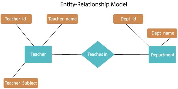
Fig 1: E - R diagram
The above E-R diagram has two entities: Teacher and Department
Teacher entity has three attributes:
Teacher_id
Teacher_name
Teacher_Subject
Department entity has two attributes: -
Dept_id
Dept_name
Relation Teaches in gives relationship between Teacher, Department.
Relationship can be of the type:
1:1 → One to one
1:M → One to many
M:1 → Many to one
M:M → Many to many
1.5.2 Relational Model: -
● Relational model uses a collection of tables to represent both data and the relationships among those data.
● This model is useful for constructing a database that can then be converted into relational model tables.
● Data is arranged in two-dimensional tables in this model and the relationship is preserved by storing a common field.
● In the relational model, the basic structure of data is tables. In the rows of that table, all information relating to a specific category is stored.
Therefore, in the relational model, tables are also known as relations.
Sample relational database
- Teacher Table
Teacher_id | Teacher_name | Teacher_Subject |
1001 | Pritisha | C++ |
1002 | Akon | DBMS |
1003 | Rahul | SE |
1004 | Raj | Data structure |
B. Department Table
Dept_id | Dept_name |
A101 | CSE |
B102 | Electronics |
C103 | Civil |
D104 | Mechanical |
C. Teaches in table
Teacher_id | Dept_id |
1001 | A101 |
1002 | B102 |
1003 | C103 |
1004 | D104 |
1.5.3 Hierarchical Model: -
● This model of the database organizes information into a tree-like structure with a single root to which all the other information is connected. The hierarchy begins from the root data and extends to the parent nodes like a tree, adding child nodes.
● A child node can only have a single parent node in this model.
● A Hierarchical model uses tree structure to represent relationship among entities.
● This model represents many real-world relationships effectively, such as a book index, recipes, etc.
● Data is structured into a tree-like structure in the hierarchical model with a one-to-many relationship between two different data forms.
For instance, one department can have many classes, many professors and many students of course.
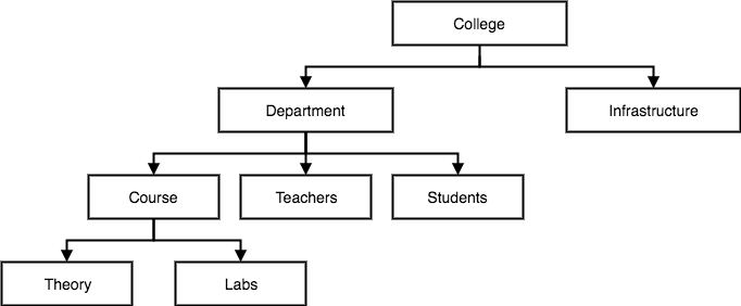
Fig 2: hierarchical model
1.5.4 Network Model: -
● Network model uses two different data structures: -
a) A record type is used to represent as entity set.
b) A set type is used to represent a directed relationship between two record types.
● This is the Hierarchical model's extension. Data is arranged more like a graph in this model, and is allowed to have more than one parent node.
● Data is more linked in this database model as more relationships are formed in this database model. Also, as the data is more linked, it is also simpler and quicker to access the information. To map many-to-many data relationships, this database model was used.
● This was the most commonly used database architecture prior to the advent of the Relational Model.
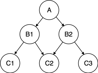
Fig 3: network model
1.5.5 Object Relational Model: -
The object-oriented database derivation is the integrity of object-oriented
Programming language systems and consistent systems. The power of the object-oriented databases comes from the cyclical treatment of both consistent data, as found in databases, and transient data, as found in executing programs.
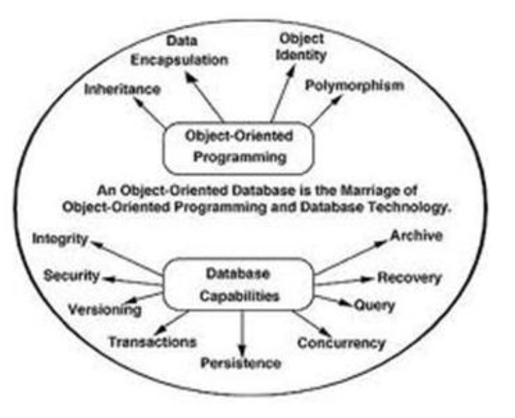
Fig 4: Object - oriented model
Object-oriented databases use small, recyclable separated of software
Called objects. The objects themselves are stored in the object-oriented
Database. Each object contains of two elements:
1. Piece of data (e.g., sound, video, text, or graphics).
2. Instructions, or software programs called methods, for what to do with
The data.
There are two types of ORM: -
a. Object-Oriented Data Model (OODM)
b. Object-Relational Data Model (ORDM)
These models are used to handle objects:
1) To provide support for complex objects.
2) To provide user extensibility for data types operators and access methods.
3) There should be mechanism to support:
a) Abstract data type.
b) Data of type ‘procedure’.
c) Rules.
Key takeaway:
- The logical structure of a database can be expressed by an E-R diagram.
- Relational model uses a collection of tables to represent both data and the relationships among those data.
- A Hierarchical model uses tree structure to represent relationships among entities.
- Network model is the Hierarchical model's extension
In addition to users' data, a database system usually includes a lot of data. For instance, to easily locate and retrieve data, it stores information about data, known as metadata. Modifying or modifying a collection of metadata once it is placed in the database is very difficult. But when a DBMS expands, in order to fulfil the users' requirements, it needs to evolve over time. It will become a boring and highly complicated job if the entire data is based.
Metadata itself follows a layered model, such that it does not impact the data at another level when we modify data on one layer. This data is independent, but is mapped to one another.
1.6.1 Types of data independences
❏ Physical data independence
Physical Data Independence is defined as the ability to make adjustments without affecting the higher-level schemas in the structure of the lowest level of the Database Management System (DBMS). Therefore, the Physical level adjustment does not result in any adjustments to the Conceptual or View levels.
❏ Logical data independence
Logical Data Independence is defined as the ability to make improvements to the Database Management System (DBMS) middle level structure without affecting the schema or application programmes at the highest level. Changes to the conceptual level should also not result in any changes to the view levels or programmes of the application.
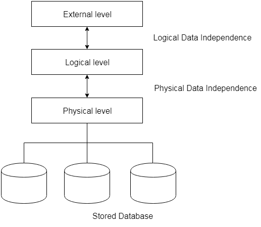
Fig 5: data independence
Key takeaway:
- The freedom of logical data refers to the ability to alter the conceptual schema without the external schema needing to be modified.
- Independence of physical data can be defined as the ability to alter the internal schema without the conceptual schema having to be modified.
You may split the database management system into five main components, which are
- Hardware
- Software
- Data
- Procedure
- Database Access Language
In order to see how they all work together to form a database management system, let's have a basic diagram.
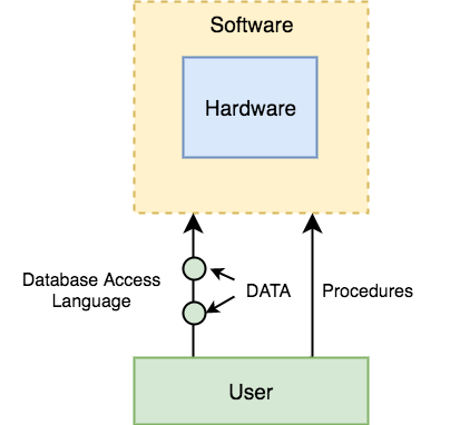
Fig 6: Component of DBMS
- Hardware
When we say hardware, before any data is successfully stored in the memory, we mean computers, hard discs, I/O channels for data, and any other physical part involved.
When we run Oracle or MySQL on our personal computer, the hard disc of our computer, the keyboard we use to type all the commands, the RAM of our computer, the ROM, all become part of the hardware of the DBMS.
2. Software
As this is the software that governs everything, this is the key part. More like a wrapper around the physical database, the DBMS programme gives us an easy-to-use interface for storing, accessing and upgrading data.
The DBMS program is able to understand and translate the Database Access Language into actual database commands in order to execute them on the DB.
3. Data
Data is the resource for which the DBMS is intended. The motive behind the creation of DBMS was to store and use information.
Data saved by the user is present in a standard database and meta data is stored.
Metadata is data about knowledge. To better understand the data contained in it, this is information stored by the DBMS.
4. Procedure
Procedures refer to general instructions for using a method to handle a database. This includes procedures for setting up and installing a DBMS, logging in and logging out of the DBMS programme, database maintenance, backups, report creation, etc.
5. Database Access language
Database Access Language is a basic language designed to access, attach, update and delete data stored in any database by writing commands.
In the Database Access Language, a user can write commands and send them to the DBMS for execution, which is then interpreted and executed by the DBMS.
The user can use the access language to build new databases, tables, insert data, fetch stored data, update data and remove data.
Key takeaway:
- Hardware means computers, hard discs, I/O channels for data, and any other physical part involved.
- software that governs everything, this is the key part.
- Data is the resource for which the DBMS is intended.
- Procedures refer to general instructions for using a method to handle a database.
- In the Database Access Language, a user can write commands and send them to the DBMS.
A system of databases is divided into modules dealing with each of the overall system's responsibilities. A database system's functional components can be narrowly divided into the components of the storage manager and the query processor. The storage manager is essential since a large amount of storage space is usually needed for databases. The query processor is important because it simplifies and promotes access to data by supporting the database system.
It is the responsibility of the database system to convert, at the logical level, changes and queries written in a non-procedural language into an effective sequence of physical level operations.
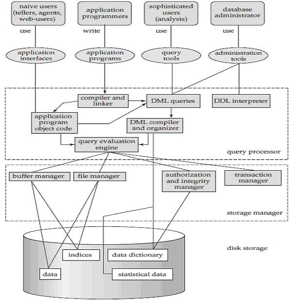
Fig 7: overall structure of DBMS
The database system is divided into three components: Query Processor, Storage Manager, and Disk Storage
❖ Query processor
It interprets the requests (queries) received from the end user into instructions through an application program. Also, the user request that is received from the DML compiler is executed.
The Query Processor comprises the following parts:
● DML compiler
The DML statements are processed into low-level (machine language) instructions so that they can be implemented.
● DDL interpreter
The DDL statements are processed into a table set containing meta data (data about data).
● Query optimization
Typically, a question can be converted into any of a variety of alternative assessment plans that all offer the same outcome. The DML compiler also performs query optimization, which is to say, among the alternatives, it selects the lowest cost evaluation plan.
● Query evaluation engine
That executes the low-level instructions that the DML compiler generates.
❖ Storage manager
A storage manager is a software module that provides an interface between the low-level data stored in the database and the system-submitted application programmes and queries. Interaction with the file manager is the responsibility of the storage manager. Using the file system, which is typically supported by a conventional operating system, raw data is stored on the disc. The storage manager converts the different DML statements into low-level commands for the file system. It is also the duty of the storage manager to store, retrieve, and update data in the database.
The components for the storage manager include:
● Authorization and integrity manager
This ensures role-based regulation of access, i.e., It checks whether or not the individual is entitled to conduct the requested activity.
When the database is updated, the integrity manager checks the integrity constraints.
● Transaction manager
It manages simultaneous access by executing the operations in a scheduled manner in which the transaction is received. It also ensures that the database stays in a consistent state before and after a transaction has been executed.
● File manager
It manages the space of the file and the data structure used in the database to represent information.
● Buffer manager
The cache memory and data transfer between the secondary storage and the main memory are responsible for this.
❖ Disk storage
It includes the following elements-
● Data files
It stores the data.
● Data dictionary
It includes details about any database object's structure. It is the information repository that regulates metadata.
● Indices
It provides faster retrieval of data items.
Key takeaway:
- A database system's functional components can be narrowly divided into the components of the storage manager and the query processor.
- A system of databases is divided into modules dealing with each of the overall system's responsibilities.
- The storage manager converts the different DML statements into low-level commands for the file system.
The architectures used to implement DBMS for multi-users are:
★ Teleprocessing
Teleprocessing was the standard architecture for multi-user systems where: there is:
● One computer with a single Central Processing Unit (CPU) and
● A number of terminals.
Within the limits of the same physical computer, all processing is done.
Usually, user terminals are 'Dumb Terminals'. They are unable to operate on their own and are connected to the central computer through a cable.
Terminals send messages through them. Sub-system for contact control.
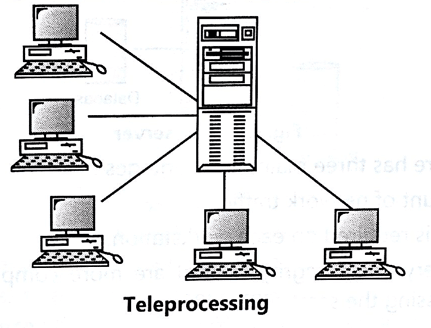
Fig 8: Teleprocessing
★ File server
The processing is spread over the network, usually the local area network, in a file server environment (LAN). The file server holds the files needed by the DBMS and the application. On each workstation, however, the applications and DBMS run, requesting files from the file server when necessary.
The file server simply functions as a shared disc of files. The DBMS sends requests to the file server on each workstation for all the data that the DBMS needs to be stored on the disc.
This strategy will create a large amount of network traffic, which can lead to problems with efficiency.
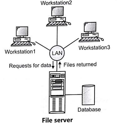
Fig 9: File server
There are three principal drawbacks to the file server architecture:
● There is a large amount of network traffic.
● A full copy of DBMS is required on each workstation.
● Concurrency, Recovery and Integrity control are more complex because there can be multiple DBMS accessing the same files.
★ Client server
The client-server architecture was designed to address the limitations of the first two approaches. As the name shows, there are:
● A client process, which requires some resource,
● A server process, which provides the resource.
There is no requirement for the client and the server to be on the same computer. The client handles the user interface and the application logic in the database sense.
● It takes the user requests.
● Check the syntax.
● Generates database requests in SQL or another database language.
● Transmits the message to the server, waits for response and formats the response for the end-user.
The server process :
● Accepts and processes the database requests.
● Transmits the result to the client
Request processing includes verifying authorization, ensuring integrity, maintaining the catalogue of the system, and processing queries and updates. In addition, it also offers control of concurrency and recovery.
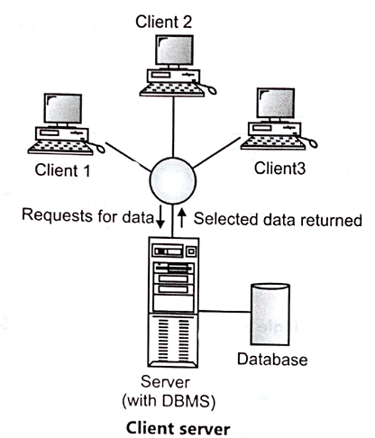
Fig 10: Client server
Key takeaway:
- The file server holds the files needed by the DBMS and the application.
- There is no requirement for the client and the server to be on the same computer, in the client server process.
- They are unable to operate on their own and are connected to the central computer through a cable, in teleprocessing.
A system catalogue is a group of tables and views that incorporate a database's vital information. The framework of the database is defined by any database consisting of a system catalogue and the information in the system catalogue.
For example, the language of the data dictionary (DDL) is saved in the system catalogue for every table in the database.
A critical element of a database is the system catalogue. There are items within the database, which include tables, views and indexes. The device catalogue is basically a collection of objects that contains information that defines:
● Other objects included in the database
● The database structure itself
● Several other vital pieces of information
It is possible to divide the device catalogue intended for implementation into logical groups of objects. This is to deliver tables that are not only available by the database administrator, but also by all other users of the database. For example, users may want to see the unique database rights they have been granted; however, they do not need to find out about the processes or internal structure of the database.
In order to obtain knowledge about the user's own objects as well as rights, a user normally looks up the system catalogue, while the database administrator must be able to ask about every occurrence or structure within the database.
Key takeaway:
- A system catalogue is a group of tables and views that incorporate a database's vital information.
- For database administrators or any other database users who wish to understand the essence and function of a database, a system catalogue is extremely necessary.
1.11.1 Basic concept
The ER Data Model is based on objects and their relationships in the real world. In other words, the object in the world of databases is created by anyone and everything, either living or non-living objects in this world. For our database specifications, we classify all the necessary objects and give the shape of the database objects.
It is very important to understand the specifications correctly and design them effectively before bringing them into the database. It is like a building foundation. We use ER diagrams for this function, where we pictorially design the database.
Basically, the ER diagram splits the demand into persons, attributes and relationships.
1.11.2 Entity
We will group only similar data together in a database and store them under one group name called Entity / Table. It helps to determine which information is stored where and under what name. In a whole database, it reduces the time to search for a specific data.
In short, all of the world's living and non-living entities form an organism. If that makes it easier, one should accept all nouns as entities.
❏ Strong entity
Entities with their own attributes as primary keys are referred to as powerful entities. For example, STUDENT, has STUDENT ID as its primary key. It is, therefore, a strong entity.
❏ Weak entity
Weak entities are entities which cannot form their own attribute as a primary key. These entities can derive their primary keys from the combination of their attributes and from their mapping entity's primary key.
Example: Consider an object with CLASS and Segment. As an attribute, the SECTION has SECTION ID and NAME. However, SECTION ID alone may not be a primary key, as it fails to say which course it is associated with. 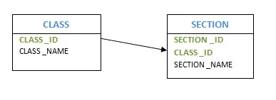
Fig 11: Example of entity
❏ Composite entity
Entities that engage in several or many interactions are referred to as composite entities. In this situation, we will have one more hidden entity in the relationship, aside from the two entities that are part of the relationship. By using the primary keys of the other two entities, we will create a new entity with the relationship, and create a primary key.
Consider the instance of several students enrolled in several courses. We are developing STUDENT and COURSE in this case. We then build one more table for the 'Enrolment' relationship and name it as STUD COURSE. Add into it the COURSE and STUDENT primary keys, which form the new table's composite primary key.
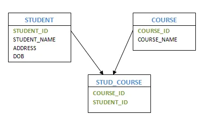
Fig 12: Composite entity
❏ Recursive entity
If there is a correlation with the same entities, then such entities are referred to as recursive entities. For example, manager-employee mapping is a recursive entity. Managers are mapped to the same employee entity here. Another instance of providing recursive entities is the department's HOD.
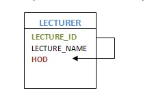
Fig 13: Recursive entity
Key takeaway:
- similar data together in a database and store them under one group name called Entity.
- It helps to determine which information is stored where and under what name.
1.11.3 Attributes
An attribute may have a single value, or a number of values, or a variety of values. Furthermore, each attribute can contain certain data types, such as a numeric value only, or an alphabet only, or a combination of both, or a date or a negative or a positive value, etc.
It is split into different forms, based on the values an attribute can take.
❏ Simple Attribute: These types of attributes have properties that cannot be further divided. For example, the attribute STUDENT ID, which cannot be further divided. Passport Number is a unique value that cannot be divided.
❏ Composite Attribute: It is possible to further split this kind of attribute into more than one basic attribute. For instance, an individual's address. Here, the address can be further divided as Door#, Street, City, State and Pin, which are simple attributes.
❏ Derived Attribute: Derived attributes are those whose meaning can be derived from other entity attributes in the database. For example, it is possible to obtain a person's age from the date of birth and current date. Examples of derived attributes are average wage, annual salary, total marks of a student, etc.
❏ Multi - valued Attribute: At any point in time, these attributes may have more than one value. The manager can have more than one worker working for him, an employee can have more than one email address, and the examples are more than one house etc.
❏ Stored Attribute: The attribute that gives the value of the derived attribute is referred to as the Stored Attribute. In the above case, age is derived from the date of birth. The Date of Birth is also a stored attribute.
Key takeaway:
- An attribute is a list of all related information of an entity, which has valid value.
- It contains certain data types, such as a numeric value only, or an alphabet only, or a combination of both, or a date or a negative or a positive value, etc.
1.11.4 Relationships
The glue that keeps the tables together is relationships. They are used between tables for connecting related data.
Relationship intensity is dependent on how a related entity's primary key is determined. If the primary key of the related entity does not include a primary key component of the parent entity, a weak, or non-identifying, relationship exists.
How two or more individuals are interrelated is defined by a relationship.
STUDENT and CLASS entities, for instance, are synonymous with 'Student X studies in a Y class.' The relationship between student and class is defined here by 'Studies.' Similarly, as 'Teacher A teaches Subject B', the teacher and subject are connected. The relationship between both the instructor and the subject is established here.
Degree of relationship
Two or more organizations may engage in a collaboration. Degrees of association are defined as the number of individuals that are part of a specific relationship. If only two individuals are interested in the mapping, then the relationship level is 2 or binary.
If there are three individuals involved, then the relation degree is 3 or ternary. If there are more than 3 people involved, then the relationship degree is called n-degree or n-nary.
Key takeaway:
- The glue that keeps the tables together is relationships.
- They are used between tables for connecting related data.
- How two or more individuals are interrelated is defined by a relationship.
1.11.5 Constraints
● A mapping constraint is a data constraint representing the number of entities to which a relationship set can relate to another entity.
● It is most useful to define relationship sets involving more than two sets of individuals.
● There are four possible mapping cardinalities for the binary relationship set R on an entity set A and B. They are as follows
- One to one (1:1)
- One to many (1:M)
- Many to many (M:M)
One to one: As we have seen in the example above, only one instance of an entity is mapped to one instance of another entity. Consider the Department's HOD. Just one HOD in one department exists. That is, the relationship between the HOD agency and the Department is 1:1.
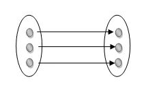
Fig 14: One to one mapping
One to many: As we can guess now, there is one instance of an entity linked to many instances of another entity between one and several relationships. In his department, one manager oversees several employees.
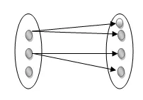
Fig 15: One to many mapping
Many to many : This is a relationship where multiple entity instances are linked to multiple entity instances.
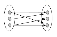
Fig 16: Many to many mapping
Key takeaway:
- It is most useful to define relationship sets involving more than two sets of individuals.
- There are four possible mapping cardinalities for the binary relationship.
1.11.6 Keys
Keys are the entity's attributes, which define the entity's record uniquely.
Several types of keys exist.
These are listed underneath:
❏ Composite key
A composite key consists of two attributes or more, but it must be minimal.
❏ Candidate key
A candidate key is a key that is simple or composite and special and minimal. It is special since no two rows can have the same value at any time in a table. It is minimal since, in order to achieve uniqueness, every column is required.
❏ Super key
The Super Key is one or more of the entity's attributes that uniquely define the database record.
❏ Primary key
The primary key is a candidate key that the database designer chooses to be used as an identification mechanism for the entire set of entities. In a table, it must uniquely classify tuples and not be null.
In the ER model, the primary key is indicated by underlining the attribute.
● To uniquely recognize tuples in a table, the designer selects a candidate key. It must not be empty.
● A key is selected by the database builder to be used by the entire entity collection as an authentication mechanism. This is regarded as the primary key. In the ER model, this key is indicated by underlining the attribute.
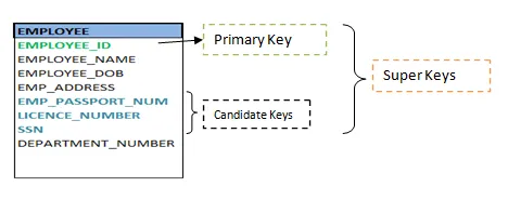
Fig 17: Shows different keys
❏ Alternate key
Alternate keys are all candidate keys not chosen as the primary key.
❏ Foreign key
A foreign key (FK) is an attribute in a table that, in another table, references the primary key OR it may be null. The same data type must be used for both international and primary keys.
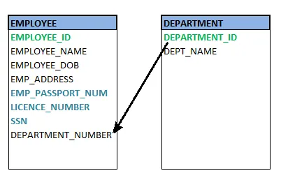
Fig 18: Foreign key
❏ Secondary key
A secondary key is an attribute used exclusively (can be composite) for retrieval purposes, such as: phone and last name.
Key takeaway:
- Keys are the entity's attributes, which define the entity's record uniquely.
- A candidate key is a key that is simple or composite and special and minimal.
- Primary key, uniquely recognize tuples in a table, the designer selects a candidate key. It must not be empty.
References:
- Silberschatz A., Korth H., Sudarshan S. “Database System Concepts”, 6th edition, Tata McGraw Hill Publisher
- Ramkrishna R., Gehrke J. “Database Management Systems”, 3rd edition, McGraw Hill
- Rab P., Coronel C. “Database Systems Design, Implementation and Management”, 5th edition, Thomson Course Technology, 2002