UNIT-4
PIC Interfacing-II
4.1.1Capture Mode
- In Capture mode, CCPRxH:CCPRxL captures the 16-bit value of the TMR1 register when an event occurs on pin CCPx. An event is defined as:
- Every falling edge
- Every rising edge
- Every 4th rising edge
- Every 16th rising edge
- An event is selected by control bits CCPxM3:CCPxM0 (CCPxCON<3:0>). When a capture is
- made, the interrupt request flag bit, CCPxIF, is set. The CCPxIF bit must be cleared in software.
- If another capture occurs before the value in register CCPRx is read, the previous captured value will be lost.
- As can be seen in Figure 14-1, a capture does not reset the 16-bit TMR1 register. This is so timer1 can also be used as the timebase for other operations.
- The time between two captures can easily be computed as the difference between the value of the second capture that of the first capture.
- When Timer1 overflows, the TMR1IF bit will be set.
CCP Pin Configuration
- In Capture mode, the CCPx pin should be configured as an input by setting its corresponding TRIS bit.
- The prescaler can be used to get a very fine average resolution on a constant input frequency.
- For example, if we have a stable input frequency and we set the prescaler to 1:16, then the total error for those 16 periods is 1 TCY.
- This gives an effective resolution of TCY/16, which at 20 MHz is 12.5 ns. This technique is only valid where the input frequency is “stable” over the 16 samples.
- Without using the prescaler (1:1), each sample would have a resolution of TCY.
- Timer1 must be running in timer mode or synchronized counter mode for the CCP module to use the capture feature. In asynchronous counter mode, the capture operation may not work.
- If the CCPx pin is configured as an output, a write to the port can cause a capture to Changing Between Capture Modes.
- When the Capture mode is changed, a capture interrupt may be generated. The user should keep the CCPxIE bit clear to disable these interrupts and should clear the CCPxIF flag bit following any such change in operating mode.
CCP prescaler
- There are four prescaler settings, specified by bits CCPxM3:CCPxM0. Whenever the CCP module is turned off, or the CCP module is not in capture mode, the prescaler counter is cleared.
- This means that any reset will clear the prescaler counter.
- Switching from one capture prescale setting to another may generate an interrupt.
- Also, the prescaler counter will not be cleared, therefore the first capture may be from a nonzero prescaler.
4.1.2Compare and PWM generation
Compare Mode
- In Compare mode, the 16-bit CCPRx register value is constantly compared against the TMR1register pair value. When a match occurs, the CCPx pin is:
- Driven High
- Driven Low
- Remains Unchanged
- The action on the pin is based on the value of control bits CCPxM3:CCPxM0 (CCPxCON<3:0>).
- At the same time, a compare interrupt is also generated.
- Timer1 must be running in Timer mode or Synchronized Counter mode if the CCP module is using the compare feature. In Asynchronous Counter mode, the compare operation may not work.
PWM Mode
- In Pulse Width Modulation (PWM) mode, the CCPx pin produces up to a 10-bit resolution PWM output.
- Since the CCPx pin is multiplexed with the PORT data latch, the corresponding TRIS bit must be cleared to make the CCPx pin an output.
|
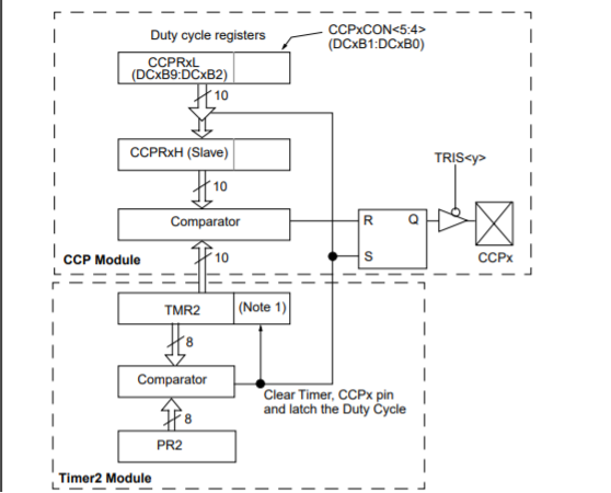
Fig.1. block diagram of the CCP module in PWM mode
PWM Period
- The PWM period is specified by writing to the PR2 register. The PWM period can be calculated using the following formula:
PWM period = [(PR2) + 1] • 4 • TOSC • (TMR2 prescale value),
specified in units of time
- PWM frequency (FPWM) is defined as 1 / [PWM period].
- When TMR2 is equal to PR2, the following three events occur on the next increment cycle: TMR2 is cleared.
- The CCPx pin is set (exception: if PWM duty cycle = 0%, the CCPx pin will not be set).
- The PWM duty cycle is latched from CCPRxL into CCPRxH.
PWM Duty Cycle
- The PWM duty cycle is specified by writing to the CCPRxL register and to the DCxB1:DCxB0(CCPxCON<5:4>) bits.
- Up to 10-bit resolution is available: the CCPRxL contains the eight MSbs and CCPxCON<5:4> contains the two LSbs.
- This 10-bit value is represented by DCxB9:DCxB0.The following equation is used to calculate the PWM duty cycle:
- PWM duty cycle = (DCxB9:DCxB0 bits value) • Tosc • (TMR2 prescale value), in units of time.
- The DCxB9:DCxB0 bits can be written to at any time, but the duty cycle value is not latched into CCPRxH until after a match between PR2 and TMR2 occurs (which is the end of the current period).
- In PWM mode, CCPRxH is a read-only register.
- The CCPRxH register and a 2-bit internal latch are used to double buffer the PWM duty cycle.
- This double buffering is essential for glitchless PWM operation.
- When CCPRxH and 2-bit latch match the value of TMR2 concatenated with the internal 2-bit Q clock (or two bits of the TMR2 prescaler), the CCPx pin is cleared. This is the end of the duty cycle.
- Maximum PWM resolution (bits) for a given PWM frequency:
- The Timer2 postscaler is not used in the determination of the PWM frequency.
- The postscaler could be used to have a servo update rate at a different frequency than the PWM output.
- If the PWM duty cycle value is longer than the PWM period, the CCPx pin will notbe cleared. This allows a duty cycle of 100%.
- This system would be able to control the DC motor speed at desired speed regardless the changes of load.
- The speed of DC motor depends on applied voltage, Armature current and applied load.
|
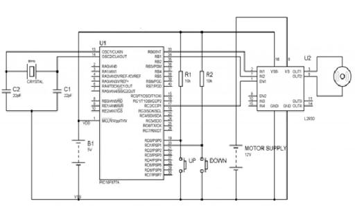
Fig.2. DC motor speed control with CPP
- Two push button switches are connected to 1st and 2nd pins of PORTD which is used to control the duty ratio of the generated PWM.
- Pressing the UP switch increases the duty cycle, which increases the motor speed while pressing the DOWN switch decreases the duty cycle, which decreases the motor speed.
- Here we use CCP1 module of PIC 16F877A to generate PWM and it is given to the enable pin of L293D.
- The direction of rotation of motor can be control using the 1st and 2nd pins of PORTB.
- There are three reasons for “Resistor is not a good choice for controlling the speed of a DC Motor”.
- The main problem is that the motor is a varying electrical load so a resistor can’t do this task.
- It needs more power during start up than in running state. It draws more current also when a mechanical load is applied to motor shaft.
- The resistor drops excess energy as heat. Thus it is not good for a battery powered device.
- We all know that motor requires more current, so resistors with higher power rating are required to drop excess energy.
- PWM can be easily generated using the inbuilt CCP module of a PIC Microcontroller.
- CCP stands for Capture/Compare/PWM. CCP modules are available with a number of PIC Microcontrollers.
- Most of them have more than one CCP module. MicroC Pro for PIC Microcontroller provides built in library routines for PWM which makes our task very simple.
- Stepper Motor is a specially designed motor which rotates in steps.
- Speed of stepper motor depends on the rate of electrical signal applied to it.
- Different patterns can control stepper motor’s direction and rotation type.
- Mainly two types of stepper motors are available, Unipolar and Bipolar.
- Unipolar is easier to operate, control and also easier to get. Here in this tutorial we are interfacing Stepper Motor with PIC Microcontroller PIC16F877A.
- We are using 28BYJ-48 stepper motor for this project which is cheap and easily available.
- It is 5V DC unipolar stepper motor. We are also using a Module available with this motor which consist ULN2003 Stepper Motor Driver IC.
- ULN2003 is a Darlington pair array, which is useful to drive this motor, since PIC microcontroller couldn’t provide enough current to drive. ULN2003A is capable to drive 500mA of load with 600mA of peak current.
Key Takeaway:
- In Capture mode, CCPRxH:CCPRxL captures the 16-bit value of the TMR1 register when an event occurs on pin CCPx.
- In Capture mode, the CCPx pin should be configured as an input by setting its corresponding
- Switching from one capture prescale setting to another may generate an interrupt.
- Speed of stepper motor depends on the rate of electrical signal applied to it.
- PWM duty cycle = (DCxB9:DCxB0 bits value) • Tosc • (TMR2 prescale value), in units of time.
4.4.1 Study of RS232:
- In RS232, ‘RS’ stands for Recommended Standard. It defines the serial communication using DTE and DCE signals.
- Here, DTE refers to Data Terminal Equipment and DCE refers to the Data Communication Equipment.
- Example of DTE device is a computer and DCE is a modem. Formally, it is specified as the interface between DTE equipment and DCE equipment using serial binary data exchange.
|
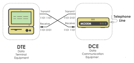
Fig.3. Study of RS232
- The DTE (computer) transmits the information serially to the other end equipment DCE (modem).
- In this case, DTE sends binary data “11011101” to DCE and DCE sends binary data “11010101” to the DTE device.RS232 describes the common voltage levels, electrical standards, operation mode and number of bits to be transferred from DTE to DCE.
- This standard is used for transmission of information exchange over the telephone lines.
4.4.2 12C:
- Like SPI, I2C is synchronous, so the output of bits is synchronized to the sampling of bits by a clock signal shared between the master and the slave.
- The following are some of the important features of I2C communication protocol:
- Only two common bus lines (wires) are required to control any device/IC on the I2C network.
- No need of prior agreement on data transfer rate like in UART communication. So the data transfer speed can be adjusted whenever required.
- Simple mechanism for validation of data transferred.
- Uses 7-bit addressing system to target a specific device/IC on the I2C bus I2C networks are easy to scale.
- New devices can simply be connected to the two common I2C bus lines.
4.4.3 SPI
- Serial Peripheral Interface (SPI) is an interface bus commonly used to send data between microcontrollers and small peripherals such as shift registers, sensors, and SD cards.
- It uses separate clock and data lines, along with a select line to choose the device you wish to talk to.
Advantages
- No start and stop bits, so the data can be streamed continuously without interruption
- No complicated slave addressing system like I2C
- Higher data transfer rate than I2C (almost twice as fast)
- Separate MISO and MOSI lines, so data can be sent and received at the same time
Disadvantages
- Uses four wires (I2C and UARTs use two)
- No acknowledgement that the data has been successfully received (I2C has this)
- No form of error checking like the parity bit in UART
- Only allows for a single master
- Hopefully this article has given you a better understanding of SPI. Continue on to part two of this series to learn about UART driven communication, or to part three where we discuss the I2C protocol.
4.4.4 UART
- UART stands for Universal Asynchronous Receiver/Transmitter. It's not a communication protocol like SPI and I2C, but a physical circuit in a microcontroller, or a stand-alone IC.
- A UART's main purpose is to transmit and receive serial data.
- No communication protocol is perfect, but UARTs are pretty good at what they do.
- Here are some pros and cons to help you decide whether or not they fit the needs of your project:
Advantages
- Only uses two wires
- No clock signal is necessary
- Has a parity bit to allow for error checking
- The structure of the data packet can be changed as long as both sides are set up for it
- Well documented and widely used method
Disadvantages
- The size of the data frame is limited to a maximum of 9 bits
- Doesn’t support multiple slave or multiple master systems
- The baud rates of each UART must be within 10% of each other
- Continue on to part three of this series, Basics of the I2C Communication Protocol to learn about another way electronic devices communicate. Or if you haven’t already, check out part one, Basics of the SPI Communication Protocol.
4.4.5 Serial communication programming using embedded C
- Set the baud rate at 9600, 8-bit data and 1 stop bit.
- Use Timer 1 for baud rte generation.
- The 8051 control registers for serial communication are shown and the Serial Port programming in Embedded C.
- Computer transfer data in two different ways:-
- SERIAL TRANSFER: In serial transfer, data is transfer to device located many meters away this method is used for long distance data transfer.
- Parallel transfer: In parallel transfer, data is transferred in 8 or more lines. In this wire conductor is used for transferring data to a device that is only a few feet away.
- Serial communication is mostly used for transmitting and receiving the signal.
- The 8051 microcontroller is consisting of Universal Asynchronous Receiver Transmitter (UART) used for serial communication.
- The signals are transmitted and received by the Rx and Tx pins of microcontroller.
- The UART take individual bytes of data and sends the individual bits in a sequential manner.
- The registers are used for collecting and storing the data inside a memory. UART is based on half-duplex protocol.
- Half-duplex means transferring and receiving the data, but not at the same time.
Serial Vs Parallel
- Data transferred by computer occurs in two ways. They are parallel and serial communication.
- Parallel Communication has 8 or more lines. It is used for transfer of data to a device that is only a short distance, while serial communication is used to transfer data over a long distance.
- The data is sent one bit at a time in serial communication, whereas multiple bits are sent simultaneously in parallel communication.
Key Takeaway:
- In RS232, ‘RS’ stands for Recommended Standard. It defines the serial communication using DTE and DCE signals.
- I2C is a serial communication protocol, so data is transferred bit by bit along a single wire (the SDA line).
- Serial Peripheral Interface (SPI) is an interface bus commonly used to send data between microcontrollers and small peripherals such as shift registers, sensors, and SD cards.
- UART stands for Universal Asynchronous Receiver/Transmitter. It's not a communication protocol like SPI and I2C, but a physical circuit in a microcontroller, or a stand-alone IC.
- The 8051 microcontroller is consisting of Universal Asynchronous Receiver Transmitter (UART) used for serial communication.
Reference:
1.Peatman, John B, “Design with PIC Microcontroller”, Pearson Education PTE
2.Microchip’s PIC18FXXX Data Sheet
3.Muhammad Ali Mazidi, SarmadNaimi,“ARM Assembly Language Programming & Architecture”


