Unit - 6
Applications of Computer Aided Engineering
Computational Fluid Dynamics:
Computational fluid dynamics (CFD) is a department of fluid mechanics that makes use of numerical evaluation and records systems to research and resolve issues that contain fluid flows.
With high-pace supercomputers, higher answers may be achieved, and are regularly required to resolve the biggest and maximum complicated issues. Ongoing studies yields software program that improves the accuracy and pace of complicated simulation situations which include transonic or turbulent flows.
Three Dimensions of fluid dynamics:
Initial validation of such software program is generally carried out the use of experimental equipment which include wind tunnels. In addition, formerly carried out analytical or empirical evaluation of a selected hassle may be used for comparison.
A very last validation is regularly carried out the use of full-scale testing, which include flight tests. CFD is implemented to a huge variety of studies and engineering issues in lots of fields of observe and industries, together with aerodynamics and aerospace evaluation, climate simulation, herbal technological know-how and environmental engineering, commercial device layout and evaluation, organic engineering, fluid flows and warmth transfer, engine and combustion evaluation, and visible consequences for movie and games.
In physics and engineering, fluid dynamics is a sub discipline of fluid mechanics that describes the float of fluids—drinks and gases. It has numerous sub disciplines, such as aerodynamics (the have a look at of air and different gases in motion) and hydrodynamics (the have a look at of drinks in motion). Fluid dynamics has a huge variety of applications, such as calculating forces and moments on aircraft, figuring out the mass float charge of petroleum thru pipelines, predicting climate patterns, know-how nebulae in interstellar area and modelling fission weapon detonation. Fluid dynamics gives a scientific structure—which underlies those realistic disciplines—that embraces empirical and semi-empirical legal guidelines derived from float size and used to clear up realistic problems.
Before the 20th century, hydrodynamics changed into synonymous with fluid dynamics. This remains contemplated in names of a few fluid dynamics topics, like magneto hydrodynamics and hydrodynamic stability, each of which also can be implemented to gases.
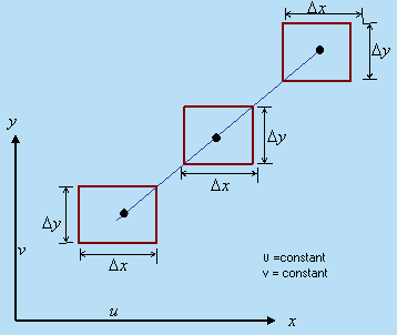
Translation of a Fluid Element
The motion of a fluid detail in area has 3 awesome capabilities simultaneously. Translation Rate of deformation Rotation. Figure 7.four suggests the photo of a natural translation in absence of rotation and deformation of a fluid detail in a two-dimensional float defined with the aid of using a square Cartesian coordinate system.
In absence of deformation and rotation,
a) There might be no alternate with inside the period of the edges of the fluid detail.
b) There might be no alternate with inside the covered angles made with the aid of using the edges of the fluid detail.
c) The facets are displaced in parallel direction.
This is feasible whilst the float velocities u (the x element velocity) and v (the y element velocity) are neither a characteristic of x nor of y, i.e., the float area is definitely uniform.
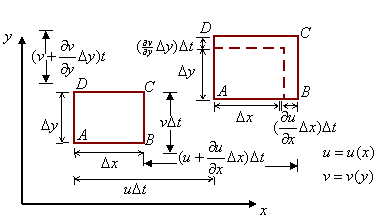
If an aspect of go with the drift pace will become the characteristic of best one area coordinate alongside which that pace aspect is defined.
For example, if u = u(x) and v = v(y), the fluid detail ABCD suffers a extrude in its linear dimensions together with translation there may be no extrude with inside the blanketed attitude via way of means of the perimeters as proven in Fig.
Vorticity additives as vectors:
The vortices is virtually an anti-symmetric tensor and its 3 wonderful factors rework just like the additives of a vector in Cartesian coordinates.
This is the cause for which the vorticity additives may be handled as vectors.
Existence of Flow
- A fluid need to obey the regulation of conservation of mass in route of its glide as it's miles a fabric body.
- For a Velocity subject to exist in a fluid continuum, the speed additives need to obey the mass conservation precept.
- Velocity additives which comply with the mass conservation precept are stated to represent a likely fluid glide Velocity additives violating this precept, are stated to explain a not possible glide.
- The lifestyles of a bodily viable glide subject is confirmed from the precept of conservation of mass.
- The particular dialogue on that is deferred to the following bankruptcy in conjunction with the dialogue on ideas of conservation of momentum and energy.
Equilibrium equations of fluid:
A fluid can help no shearing strain whilst in equilibrium. The strain for compression is truly the stress. If there aren't any any outside forces (consisting of gravity), the stress is the equal anywhere with inside the fluid whilst the fluid is in equilibrium.
Fluid statics or hydrostatics is the department of fluid mechanics that research the circumstance of the equilibrium of a floating frame and submerged frame "fluids at hydrostatic equilibrium and the strain in a fluid, or exerted through a fluid, on an immersed frame".
It is likewise applicable to geophysics and astrophysics (for example, in know-how plate tectonics and the anomalies of the Earth's gravitational field), to meteorology, to medicine (with inside the context of blood strain), and plenty of different fields. Hydrostatics gives bodily causes for lots phenomena of ordinary life, along with why atmospheric strain adjustments with altitude, why wooden and oil flow on water, and why the floor of nonetheless water is constantly level.
1. Gravity on fluids
When handling a fluid, we now not have factor masses. Forces consisting of gravity act on fluid factors that are similar to quantity factors. This results in the concept of a frame pressure (pressure according to quantity). For gravity, this becomes:
f = ρg = -ρgy , where ρ is the mass per volume, ρ = dm/dV.
Newton’s 2nd law becomes (with P being the pressure):
Fx = +Pleft dAleft - Pright dAright = 0
Fz = +Pin dAin – Pout dAout = 0
Fy = +Pbottom dAbottom – Ptop dAtop -ρg dV = 0 .
The volume element can be written as:
DV = dx dy dz = dAxz dy , so that, with dAtop = dAbottom = dAxz, we have
Pbottom – Ptop = ρg Δy .
This can be generalized for a body force to be:
P2 – P1 = ΔP = r1r2 f • dr , or f = P .
Note that the constant pressure lines (actually surfaces) are perpendicular to the body force, f. Also, since P = 0, we have f = 0, which allows us to have:
P(r) – Po = ror f dr which is similar to a potential energy.
2. Bulk Modulus
The Bulk Modulus, B, is described as: B = pressure/ stress, in which pressure is clearly the pressure, P; and stress is ΔV/V: B = PV/ΔV, so we have -dV/V = dP/B. The minus signal comes from changing the ΔV right into a dV, however noting that the ΔV is a lower with inside the volume, now no longer an increase. Let’s now bear in mind density, ρ = m/V. The amount dρ is
dρ = d(m/V) = m d(1/V) = m {d(1/V)/dV} dV = m (-1/V2) dV,
So that the quantity dρ/ρ becomes:
dρ/ρ = m (-1/V2) dV / (m/V) = -dV/V .
Note that whenever dV increases, dρ decreases, and
When dV decreases, dρ increases. Hence the difference in the sign.
Putting -dV/V = dP/B together with dρ/ρ = -dV/V gives:
dρ/ρ = dP/B,
And integrating both sides gives:
Ln [ρ/ρo] = PoP (1/B) dP, or
ρ = ρo exp [PoP (1/B) dP ]
3. Four special cases
Case 1: incompressible fluid
When we have incompressible fluid (B ≈ ∞), then ρ ≈ constant, so using Pbottom – Ptop = ρg Δy we have:
Pbottom = Ptop + ρgh , where h = height (or depth) of the fluid.
Case 2: Bulk modulus is constant
Here we consider the case where the bulk modulus is a constant, independent of pressure and density. In this case, the density equation gives:
ρ = ρo exp [PoP (1/B) dP ] = ρo exp [P/B – Po/B] .
The pressure equation gives us:
Pbottom – Ptop = ρg Δy , or
DP = ρg dy = ρo exp{P/B – Po/B} g dy = ρo eP/B e-Po/B g dy.
We can separate this equation to get:
e-P/B dP = ρo e-Po/B g dy , or
PoP e-P/B dP = yo y ρo e-Po/B g dy
And with yo = 0 (measured from the surface) and Po = atmospheric pressure (at the surface), we have upon integration:
(-B) e-P/B – (-B)e-Po./B = ρo e-Po/B g y
Case 3: Ideal gas at constant Temperature
For an ideal gas, we have the ideal gas law:
PV = nRT
Where n is the number of moles, R is the gas constant (R = 8.3 J/mole-K), and T is the temperature (in an absolute scale such as Kelvin). This relates the volume to the pressure, and hence the density to the pressure:
ρ = m/V = m / {nRT/P} = Pm/nRT .
The m is the mass, and n is the number of moles. We can combine these two to get the mass per mole, M = m/n, so the
ρ = PM/RT
We can now use this in the relation for pressure:
DP = ρg dy = (PM/RT)g dy .
This can be separated and integrated to give:
PoP (1/P)dP = yo y (Mg/RT) dy, or
Ln {P/Po} = Mgy/RT , or P = Po e(Mg/RT)y
The above has y as the “depth” where P increases. To make it into a height (where P decreases), we must put in a negative sign for the y:
P = Po e-(Mg/RT)y
Conversations form of fluid flow equation:
Conservation shape or Eulerian shape refers to an association of an equation or machine of equations, typically representing a hyperbolic machine, that emphasizes that a belongings represented is conserved, i.e. a sort of continuity equation.
Conservative shape has an advantage: its fundamental shape permits discontinuous solutions (main to Rankine-Hugoniot relation and accurate surprise speed). Non-conservative shape does now no longer have one of these character (it permits best easy differentiable solutions).
Discrete conservation is essential in computing shocks. If conservation is violated, a surprise may also journey at an incorrect speed. Successful non-conservative schemes may also flip out to meet a few shape of discrete conservation.
Rather than conservation itself, its miles extra essential to apply a proper conservation shape (want to select out proper portions that ought to be conserved) considering that a incorrect conservation shape can result in an incorrect surprise speed.
Conservative equation is primarily based totally at the precept of conservation of mass. It states, “When a fluid flowing eleven though the pipe at any section, the amount of fluid in line with 2d stays constant”.
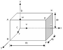
Consider a fluid element of lengths dx, dy, dz in the direction of x, y, z.
Let u, v, w are the inlet velocity components in x,y,z direction respectively.
Let ρ is mass density of fluid element at particular instate.
Mass of fluid entering the face ABCD (In flow)
= Mass density x Velocity x-direction x area of ABCD
= ρ x u x (∂y x ∂z)
Then mass of fluid leaving the face EFGH (out flow) = (ρu∂y . ∂z) + ∂ / ∂x (ρu∂y∂z)
Rate of increases in mass x-direction = Outflow – Inflow
= [ (ρudydx) + ∂ / ∂x (ρudydz) dx ] - (ρudydz)
Rate of increases in mass x direction = ∂ / ∂x ρ u dx dy dz
Similarly,
Rate of increase in mass y-direction = ∂ / ∂y ρ v ∂x ∂y ∂z
Rate of increases in mass z-direction = ∂ / ∂z ρ w ∂x ∂y ∂z
Total rate of increases in mass = (7.7.3) + (7.7.4) + (7.7.5)
= ∂x ∂y ∂z [ ∂ρu / ∂x + ∂ρv / ∂y + ∂ρw / ∂z ]
By law of conservation of mass, there is no accumulation of mass, and hence the above quantity must be zero.
∂x. ∂y. ∂z [ ∂ρu / ∂x + ∂ρv / ∂y + ∂ρw / ∂z ] = 0
∂ (ρu) / ∂x +∂ (ρv) / ∂y + ∂ (ρw) / ∂z = 0........for compressible fluid
If fluid is incompressible, then is constant
∂u / ∂x + ∂v / ∂y + ∂w / ∂z = 0
This is the continuity equation for three-dimensional flow.
NOW, for tow-dimensional flow, the velocity component w = 0
Hence continuity equation is, ∂u / ∂x + ∂v / ∂y = 0
Integral form of the conservation laws:
- The essential shape of the overall equations is a macroscopic assertion of the concepts of conservation of mass and momentum for what's referred to as a manipulate quantity. A manipulate quantity is a conceptual tool for in reality describing the diverse fluxes and forces in open-channel float. A conceptual manipulate quantity for open-channel float is proven in determine 9.
- The downstream face of the manipulate quantity at station Equation is also assumed to be orthogonal to the float course. The aspects and backside of the manipulate quantity are fashioned via way of means of the edges and backside of the channel.
- The pinnacle of the manipulate quantity is fashioned via way of means of the water surface. The period of the manipulate quantity, Equation , does now no longer need to be small and is measured alongside the space axis described previously.
- The essential shape of the equations may be defined clearly in a 1-D approximation; therefore, the equations are offered right here without derivation, accompanied via way of means of dialogue of what every principal time period or set of phrases represents with inside the conservation principle.
- To preserve the information as easy as possible, the burden coefficients used to accurate sure integrands with inside the essential shape for the results of curvilinear float are neglected at first. These weights are delivered later while the overall shape of the equations is advanced for curvilinear channel alignments.
Conservation of Mass
The conservation of mass principle for a control volume is
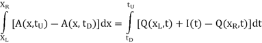
The time c language of integration is described via way of means of factors in time, Equation and Equation, such that Equation. (The means of the subscripts on those time factors is defined in greater element in next sections.)
The time period I(t) denotes the influx of water that enters the manipulate quantity over or thru the perimeters of the channel. Density is consistent and isn't proven in equation 27 due to the fact every time period might have a consistent multiplier that cancels from the relation.
Thus, the conservation of mass is equal to conservation of water quantity in FEQ simulation. Equation 27 is a unique mathematical assertion of an easy concept. The left-hand facet of equation 27 is the alternate in quantity of water contained with inside the manipulate quantity at some stage in the time c language Equation.
The quintessential of waft place with admire to distance at a hard and fast time defines the quantity of water with inside the manipulate quantity at that point. The right-hand facet of equation 27 is the internet quantity of influx to the manipulate quantity (influx minus outflow) at some stage in the time c language.
Water enters from upstream, Equation, leaves downstream, Equation, and enters over or thru the perimeters of the channel, I(t). Thus, equation 27 suggests that the alternate in quantity of the water with inside the manipulate quantity at some stage in any time c language is same to the distinction among the quantity of influx and the quantity of outflow at some stage in that point c language.
The time period I(t) represents what's typically referred to as the lateral influx, which comes from numerous sources: runoff from the land surface, discharges from sewers, outflows of water from pumping, and others. If the lateral waft is out of the channel, then I(t) is negative.
Conservation of Momentum
The precept of conservation of water quantity consists of best the flows and modifications in volumes. The conservation of momentum consists of the momentum flux and numerous forces at the obstacles of the manipulate quantity.
As mentioned previously, initial proof from laboratory research suggests that the vector nature of momentum does now no longer notably have an effect on 1-D flows; therefore, glide is dealt with as though it had been all with inside the identical path.
Impulse is a time essential of a force. In maximum fundamental fluid mechanics texts (for example, Streeter and Wylie 1985, p. 117), the conservation of momentum for a manipulate quantity in a single dimension, x, is expressed as (28)
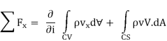
Where
Fx are the forces acting on the control volume, CV;
vx is the velocity in the x-direction;
d is the volume differential;
V is the velocity vector; and
DA is the differential area taken as a vector normal to the control surface, CS, of the control volume.
Key Takeaways:
- Computational fluid dynamics (CFD) is a department of fluid mechanics that makes use of numerical evaluation and records systems to research and resolve issues that contain fluid flows.
- Fluid dynamics gives a scientific structure—which underlies those realistic disciplines—that embraces empirical and semi-empirical legal guidelines derived from float size and used to clear up realistic problems.
- If an aspect of go with the drift pace will become the characteristic of best one area coordinate alongside which that pace aspect is defined.
- Discrete conservation is essential in computing shocks. If conservation is violated, a surprise may also journey at an incorrect speed. Successful non-conservative schemes may also flip out to meet a few shape of discrete conservation.
Injection moulding of plastics:
Our plastic injection moulding technique produces custom - fast prototypes and end-use manufacturing components in 15 days or less. We use aluminum moulds that provide cost-green tooling and increased production cycles, and inventory extra than one hundred exceptional thermoplastic resins.
We have injection moulding carrier options—prototyping and on-call for production—with every supplying their personal blessings relying for your undertaking needs. If element portions are higher, a lower priced piece-element rate is vital and quick-flip manufacturing during the product lifestyles cycle is critical. For this our on-call for production choice is ideal. The thermoplastic injection moulding technique at Portola’s is a popular technique regarding an aluminum mould.
Resin pellets are loaded right into a barrel in which they may in the end be melted, compressed, and injected into the mold’s runner system. Hot resin is shot into the mold hollow space thru the gates and the element is moulded. Ejector pins facilitate elimination of the element from the mold in which it falls right into a loading bin. When the run is complete, components (or the preliminary pattern run) are boxed and shipped rapidly thereafter. Request your Free Design Cube which suggests floor finishes and thick and skinny finishes.
Simplification of mould geometry for FEA, material model for modul FEA, boundry conditions for mould FEA, loading of mould in FEA, results analysis:
- Over the years, the term “Design Analysis” has determined a good sized area for itself with inside the production sector. Instead of creating a prototype and developing difficult trying out regimens to investigate the bodily conduct of a product, engineers can evoke this statistics quick and as it should be at the laptop.
- If an item will smash or deform or how it can react to warmth are the form of queries layout evaluation can answer. Design evaluation enables in minimizing or maybe cast off the want to construct a bodily prototype for trying out. As a result, the era has long gone mainstream as a prized product improvement device and determined its presence in nearly all sectors of engineering.
- Finite Element Analysis (FEA) Computational Fluid Dynamics (CFD) Mold Flow Analysis The Finite Element Analysis (FEA) is a specialized simulation of a bodily entity the use of the numerical set of rules referred to as Finite Element Method (FEM).
- It is used to lessen the wide variety of bodily prototypes and experiments and examine items of their layout level to increase higher merchandise quicker.
- The term ‘finite’ is used to indicate the limited, or finite, wide variety of levels of freedom used to version the conduct of every element.
- FEA will examine an item in query through breaking down its whole geometry into small ‘factors,’ that are placed beneath simulated situations see how the factors react.
- It presentations the effects as color-coded 3-d photographs in which crimson denotes a place of failure, and blue suggests fields that keep their integrity beneath the weight carried out.
- However, be aware it down that FEA offers an approximate option to the problem.
- Mathematics is used to recognize and quantify a bodily phenomenon consisting of structural or fluid conduct, wave propagation, thermal transport, the increase of organic cells, etc.
- Most of those approaches are defined the use of Partial Differential Equations. Finite Element Analysis has demonstrated to be one of the maximum distinguished numerical approach for a laptop to clear up those PEDs.
- FEA is utilized in: Problems in which analytical answer isn't effortlessly obtained, and mathematical expressions required due to complicated geometries, loadings and cloth residences.
- Computational Fluid Dynamics (CFD) Computational Fluid Dynamics (CFD) is a specialized simulation used for the evaluation of fluid flows via an item the use of numerical answer strategies.
- CFD includes carried out mathematics, physics and computing software program to assess how a fuelling or liquid flows and the way it influences an item because it flows past.
- CFD is primarily based totally on Navier-Stokes equations which describe the manner velocity, temperature, strain, and density of a transferring fluid are related. Aerodynamics and hydrodynamics are engineering streams in which CFD analyses are frequently used. Physical portions consisting of elevate and drag or discipline residences as pressures and velocities are computed the use of CFD.
- Fluid dynamics is hooked up with bodily legal guidelines with inside the shape of partial differential equations. Engineers rework those legal guidelines into algebraically equations and might correctly clear up those equations numerically. The CFD evaluation reliability relies upon at the complete shape of the procedure.
- The dedication of right numerical strategies to increase a pathway via the answer is exceedingly critical.
- The software program, which conducts the evaluation is one of the key factors in producing a sustainable product improvement procedure, as the quantity of bodily prototypes may be decreased drastically.
- CFD is utilized in nearly all commercial domain names, consisting of: Food processing Water treatment Marine engineering Automotive Aerodynamics Aerospace With the assist of CFD, fluid glide may be analyzed quicker in extra element at an in advance level, than through testing, at a decrease price and decrease risk.
- CFD solves the essential equations governing fluid glide approaches, and presents statistics on critical glide traits consisting of strain loss, glide distribution, and combining rates.
- CFD has turn out to be a fundamental a part of engineering and layout domain names of distinguished agencies because of its capacity to expect overall performance of latest designs and it intends to stay so.
- Mold Flow Analysis Mold flow, previously referred to as C-mould, is one of the main software program utilized in process wide plastics solutions. Mold glide computes the injection molding procedure in which plastic flows right into a mildew and analyzes the given mildew layout to test how the elements react to injection and make sure that the mildew might be capable of produce the most powerful and uniform pieces.
- Two of the maximum famous mildew glide evaluation software program are Mold flow and Moldex3D used solely through many mildew makers.
- There are 3 sorts of Mold glide evaluation that are as follows: Mold flow Filling Analysis (MFA): It helps visualization of shear price and shear pressure plus dedication of fiber orientation and venting.
- MFA can expect fill sample and injection strain even as optimizing gating and runner system. Mold flow Cooling Analysis (MCA): MCA makes a specialty of locating warm spots and calculating time to freeze.
- It enables in figuring out choppy cooling among center and hollow space even as specifying required cooling glide rates. Mold flow War page Analysis (MWA): Mold flow war page is all approximately predicting, locating and figuring out war page because of orientation.
- We can see advantages of the use of distinctive evaluation techniques that successfully recognize the electricity of the distinctive simulation tools.
- During the product layout, many those strategies have an effect on the price and first-rate of the product, thereby making sure the best productiveness as aimed through the manufacturer.
Loading on mould:
The gift disclosure pertains to a technique of loading and unloading a mould on a foam plastics molding device.
It is an item of the existing disclosure to offer a technique of loading and unloading a mould on a foam plastics molding device, configured to get rid of sure of the above defined drawbacks.
According to at least one embodiment of the existing disclosure, there's supplied a technique of loading and unloading a mould on a foam plastics molding device comprising a hard and fast body having a window for receiving the mildew and positioned at a better stage than the assisting floor of the device, in which loading the mildew onto the device comprising:
a primary step of putting in place and connecting to the mildew an interface body interfacing the device and the mildew, to shape a molding unit, which contains the mildew and relative interface body, and has some of plastic molding fabric and running fluid inlets;
a 2nd step of advancing the molding unit in the direction of the constant body;
a 3rd step of lifting the molding unit to the extent of the window; and a fourth step of loading the molding unit into a piece role bodily and functionally enticing the constant body on the window; and locking the molding unit to the constant body with the aid of using a locking device;
In which the second one step contains the sub-steps of: positioning the molding unit in a given constant first role at the mattress of a trolley; and shifting the trolley right into a role astride a platform defining a horizontal assisting floor for the mattress of the trolley;
And the 0. 33 step contains lifting the molding unit resting at the trolley, and contains the sub-steps of: elevating the platform, in order that vertical ribs at the interface body, that is located with inside the given first role at the trolley, slide ably interact corresponding vertical courses at the device,
Locking the ribs to the relative courses with the aid of using a locking device, while the molding unit is located coaxial with the window; and liberating the molding unit at the courses with the aid of using decreasing the platform and the trolley to detach the trolley from the molding unit.
Pressure to lessen prices of tooling requires higher and greater up-the front engineering. How? By optimizing the usage of metals round cavities for instance, that without delay pertains to the quantity of machining, heating and cooling, press clamping, logistics, garage and recycling, however mainly, via way of means of doing matters proper the primary time.
All of those goals may be done via way of means of collaboration and the adoption of simulation technology primarily based totally on finite detail evaluation (FEA), in preference to via pricey and time-consuming “trial-and-error” on every company's keep floor, individually.
Mold makers have advanced step-via way of means of-step pointers for taking a purchaser’s concept for a product via element shaping, initial plastics requirements, layout considerations, layouts, checklists, and operating and meeting drawings.
However, evaluation is regularly restrained to molding issues and solutions—glide balancing except hollow space format and positioning—via collaboration with the purchaser, and warm manifold and resin suppliers; the scale of tooling has by no means been really scrutinized. In actuality, the structural evaluation of a device or mildew, a step to insert after layout and previous to drafting for keep manufacturing, includes: Testing the fabric from which to make a device or mildew.
Defining most permissible deformation and strain degrees in regions of the device or mildew. FEA version constructing, which mixes the subsequent sub-categories: Geometry of device or mildew from CAD Definition of a tooling fabric version mounting of the mould on a press
Mold Simulation Example
The following instance demonstrates the electricity of simulation in optimizing a well-known mildew (see Figure 1). A three-D geometry of the mould become first of all received from an after-marketplace U.S. Plastics molder with inside the STEP format. This become then examine right into a FEA pre-processor for guidance of a pc-primarily based totally (or digital) version of the mould in operation.
Simplification of Mold Geometry for FEA
To lessen the scale of version and run time at the pc, the mould proven right here become decreased to 1/2 of via way of means of distinctive feature of symmetry.
Also, pc evaluation have to begin with an issue at a time, consisting of the hollow space plate in this situation.
More elements may want to then be brought to an evaluation as additives get optimized in a digital environment (previous to ordering metal or machining elements for trials).
Material Model for Mold FEA
For layout functions in FEA, simplest fabric constants on tooling fabric are necessary:
(1) the pliability or Young’s modulus that's the slope of the linear response to pulling a chit in unit of strain; and,
(2) Poisson’s ratio which pertains to the contraction of coupon whilst stretching. In this situation 29 ksi and 0.three had been respectively used off a substances database for modeling.
Boundary Conditions for Mold FEA
Here, a “mirror” circumstance become assigned to the aircraft reducing the mould in, to account for the lacking 1/2 of via way of means of symmetry. Other boundary situations consist of compression simplest at the bottom 1/2 of the mould except restraints on the slots.
Analyzing a complete or part of the mould with the proper boundary situations is to be precisely the same (besides that the decreased-sized version would "run" plenty quicker on a pc as compared to the widespread version).
Loading of Mold in FEA
“Loading” a mildew includes press tonnage or clamp pressure and injection stress in element hollow space, as proven in Figure 2.
Pressure via way of means of the molten plastics may want to come from a “mildew fill” evaluation or assumed to be at most deliverance of the press, as become the case right here. Nonetheless, the evaluation being linear elastic, deformations and stresses with inside the mildew will continue to be proportional to the implemented loads.
Results Analysis
While stresses are of high significance in assessing a mildew, whilst post-processing FEA consequences, displacements have to be checked out first to peer if a tooling evaluation (static structural on this case) become nicely set and finished properly.
Color contours of displacements in area confirmed 0 values on the mounting slots and commencing of the hollow space plate beneath inner stress—the best blue contour corresponds to 0. 049 inch with inside the lateral direction. Transitions from least to most displacement contours are slow and make experience in distribution and magnitude.
Color contours of von Misses equal strain (combining all tensile and shear additives of stresses in all 3 guidelines and plans) proven in Figure three suggest that maximum of the mould—besides for the lowest of the element hollow space and mounting slots—is under the yield strain of structural metal used on this study.
Color contours of deformations, traces and/or stresses can curiously be plotted on non-deformed or deformed geometries, or in fact, on deformed geometries with non-deformed ones nevertheless drawn for reference (to assist a mildew fashion dressmaker or analyst determine FEA outputted consequences quick and efficiently).
Mold Optimization
After inspecting the consequences of the version-constructing stage, the geometry of the unique 1/2 of plate of the mould proven become lower back to the FEA pre-processor to without difficulty adjust its general size.
The purpose become to slender down the block of metal required for the process at a tool shop, dashing its delivery, decreasing its machining, easing the locating of a press on the purchaser for molding the elements, even as quickening the heating and cooling of plastics and element in production.
Key Takeaways:
- The thermoplastic injection moulding technique at Portola’s is a popular technique regarding an aluminum mould.
- . As a result, the era has long gone mainstream as a prized product improvement device and determined its presence in nearly all sectors of engineering.
- FEA is utilized in: Problems in which analytical answer isn't effortlessly obtained, and mathematical expressions required due to complicated geometries, loadings and cloth residences
- The dedication of right numerical strategies to increase a pathway via the answer is exceedingly critical.
- During the product layout, many those strategies have an effect on the price and first-rate of the product, thereby making sure the best productiveness as aimed through the manufacturer.
Manufacturing simulation is the usage of pc modeling to simply check production strategies and procedures – which include tactics which includes manufacturing, meeting, stock, and transportation. This significantly reduces the time and prices that bodily trying out of a production gadget could incur. Simulation software program may be used to expect the overall performance of a deliberate production gadget and to evaluate answers for any issues found with inside the gadget's design. This makes production simulation a considerably aggressive capability - permitting producers to check various situations earlier than shopping for tooling, booking capability, or coordinating different luxurious manufacturing resources.
In addition to validating all-new way of manufacturing early with inside the product lifecycle, production simulation also can be implemented to present centers or tactics to pick out inefficiencies or to research the effect of introducing new equipment, materials, or different changes.
Some not unusual place factors of producing that simulations can assist with include:
- Design and balancing of meeting lines
- Throughput and capability planning
- Production logistics and cloth flow – which include transportation control and facility relocations or additions
- Management of stock levels, replenishment rates, batch sizes, manufacturing planning, etc.
- Facility format and useful resource allocation
- Clarity of labor commands and revision control
- Programming robotics and automation equipment Improving construct exceptional and validating opportunity uncooked materials
The aggregate of casting and forging is a revolutionary production approach to carry collectively the first-class from each nicely-hooked up technologies.
The technique combines the primary gain of casting, that is, complicated geometry generation, with the first-class of forging, that is, excessive power and strong mechanical houses.
Simultaneously, a discount of cloth utilization and a shortening of manufacturing steps turns into viable with the aid of using this method aggregate. Furthermore, the forging method may be used to decrease or get rid of defects because of the casting method which includes blowholes or pores.
In order to attain those benefits the aggregate of each disciplines could be essential on the product improvement phase. It is the very purpose of the existing paper to satisfy this call for with the aid of using linking and comparing the simulations of each method types.
Furthermore, investigations are recognized to clear up issues in blockading the cloth float in natural forging with the aid of using generating a solid preform for closed die forging, five wherein the provided answer is primarily based totally at the manufacturing of various castings to analyze the shape filling at some point of forging without simulative Another technique for combining casting and forging is associated with the improvement of in part solid additives of ductile solid iron with tailored houses.6
Practical forging trials at one-of-a-kind levels of forging and at one-of-a-kind temperatures and the subsequent tensile exams had been finished for contrast with tensile exams on best solid take a look at bars. In order to be expecting the element houses whilst warding off giant exams, a simulative aggregate of each character approaches, as provided on this paper, is essential.
Both, casting and forging have nicely evolved however separated equipment for the simulation of the approaches for shape filling and solidification and, respectively, forming and cloth float. When thinking about additives produced on this aggregate, it's miles vital to switch the applicable outcomes of the casting simulation to the forging simulation and to look at them in addition.
So far, the gain of related simulation is best investigated with inside the area of producing of semi-completed merchandise which includes blooms or bars.7, eight The authors describe the reuse of outcomes of a casting evaluation for incremental forging simulation.
This repeated alternate in forming route mixed with an excessive diploma of forming enables the remaining of present casting defects like pores and shrinking blowholes.
Recent studies with the aid of using the business enterprise Tubacex (Spain) with a brand new ingot layout to satisfy excessive excellent necessities offers with the contrast of various production strategies, blooming and forging. Each of the producing routes starts off evolved with the casting operation of a 6.three lots chrome steel ingot.
The utility of the method aggregate casting – forging for the manufacturing of metallic additives with best one forming step makes it even extra critical to be expecting the predicted element houses the usage of related simulations. The authors do now no longer recognize in addition present day investigations on this area.
Sheet metal applications:
Strength – sheet steel is famed for its strength
Resistant – sheet steel is sun, moisture and corrosion resistant
Light – because of sheet steel being fairly light-weight it is straightforward to move and deliver
Durable – sheet steel is long lasting sufficient to face up to excessive pressure
Pliable – sheet steel is malleable making it best for precision processes
Sustainable – sheet steel is non-poisonous to the surroundings and may be recycled
Repairable – sheet steel may be repaired easily
Availability – sheet steel is to be had globally
Cost-effective – sheet steel is fairly cheaper because it isn't always rare
Quality – sheet steel is of excessive quality
Quick – lead instances on sheet steel fabrication are generally short
Adaptable – sheet steel fabrication can cope with each low and excessive-extent production
Finishes – sheet steel gives diverse completing options
Fabrication processes – exclusive fabrication techniques are viable with sheet steel
Key Takeaways:
- Throughput and capability planning
- Programming robotics and automation equipment Improving construct exceptional and validating opportunity uncooked materials
- When thinking about additives produced on this aggregate, it's miles vital to switch the applicable outcomes of the casting simulation to the forging simulation and to look at them in addition.
- This repeated alternate in forming route mixed with an excessive diploma of forming enables the remaining of present casting defects like pores and shrinking blowholes.
The cowcatcher set up on the underframe of electrical a couple of units (EMU) is able to cleansing up boundaries from the tune and easing influences in crashing. During its long time of operation, fatigue failure subjected to alternating hundreds is the primary failure mode of EMU factor failure
Thus, cyclic operation of the cowcatcher is clearly a fatigue harm accumulation process. When the buildup harm reaches a crucial value, the cowcatcher fatigue occurs. Therefore, its miles of significance to assess and verify the reliability and fatigue sturdiness of the cowcatcher. Cowcatcher is a essential factor to comb away the boundaries and take in kinetic power.
Some researches on cowcatcher had been conducted. Ding and Zhao2 followed a brand new power soaking up shape and filling fabric with the software of collision-resistant gadget layout primarily based totally on LS-DYNA simulation. They indicated that the brand new sort of cowcatcher optimization scheme is to be had for soaking up power and easing collision.
Also, whilst designing the cowcatcher, it's miles vital to pay interest now no longer most effective to the fundamental circumstance parameters, such as its shape, top and static electricity, however additionally to its power absorption overall performance to satisfy the safety necessities for easing the influences.
To enhance the provider existence and make sure the protection at the same time as cars are in motion, it's miles vital to take the fatigue sturdiness into in addition consideration. Three Shen et al. Four supplied a suggestion to evaluate fatigue sturdiness of automobile exhaust gadget the use of finite element (FE) simulations.
- Fatigue electricity is the very best strain that a fabric can resist for a given range of cycles without breaking.
- Fatigue electricity is tormented by environmental factors, consisting of corrosion.
- The most strain that may be carried out for a positive range of cycles without fracture is the fatigue electricity.
- The range of cycles that a steel can bear earlier than it breaks is a complicated feature of:
- Static and cyclic strain values.
- Alloy.
- Heat-remedy and floor circumstance of the material.
- Hardness profile of the material.
- Impurities with inside the material.
Fatigue electricity is used to explain the amplitude (or range) of cyclic strain that may be implemented to the cloth without inflicting fatigue failure, or the best strain that a cloth can face up to for a given wide variety of cycles without breaking.
The trendy fatigue electricity for copper alloys is that pronounced for 100,000,000 cycles.
At stresses above this fatigue electricity, fewer cycles may be carried out earlier than failure; at decrease stresses, the metallic will face up to greater cycles earlier than failure.
For example, ferrous alloys and titanium alloys have a awesome restriction, underneath which there seems to be no wide variety of cycles so one can purpose failure.
Other structural metals which include aluminum and copper do now no longer have an awesome restriction and could subsequently fail even from small strain amplitudes.
Fatigue electricity is as essential to the layout of elements with excessive deflection cycles, as yield electricity is to the fashion dressmaker who need to reap considered necessary touch forces.
Orientation influences the fatigue electricity.
Data normally compiled and posted are for check specimens with a longitudinal orientation (their period is parallel to the rolling direction).
But fatigue electricity may be measurably stricken by the way wherein the component is located at the strip for stamping.
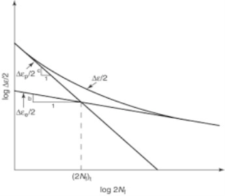
Stress-life approach (S-N method) and strain life approach (E-N method):
Stress-life approach:
- In the stress-existence approach of fatigue analysis, the elastic and plastic deformation of the fabric is used to decide what number of cycles the fabric will ultimate earlier than failure. In this context, failure is described because the formation of a small crack (normally 1mm) so the geometry of the fabric does now no longer want to be taken into consideration supplied the fabric properties had been as it should be measured the usage of a strain-stress test.
- This segment of the documentation describes 3 features that are beneficial in stress-existence analysis.
- The first of those is beneficial to healthy the strain-stress and stress-existence fashions to be had data, thereby offering the fabric properties.
- The 2d characteristic is a diagram of the connection among strain and stress at some point of cyclic fatigue which indicates the hysteresis loop and reveals the min and max strain and stress.

- The 1/3 characteristic produces the stress-existence diagram and the equations for this diagram are used for calculating the wide variety of cycles to failure. Further element is to be had under for every of the respective features.
- While those discussions pertain to micromechanical processes, phenomenological continuum methods are extensively used to symbolize the full fatigue lifestyles as a characteristic of such variables because the carried out pressure range, pressure range, suggest pressure and environment.
- These pressure- or pressure-primarily based totally methodologies, to be tested in Part two, encompass the harm evolution, crack nucleation and crack increase ranges of fatigue right into a single, experimentally characterizable continuum formulation.
- In those methods, the fatigue lifestyles of a aspect is described as the full wide variety of cycles or time to result in fatigue harm and to provoke a dominant fatigue flaw that's propagated to very last failure.
- The philosophy underlying the cyclic pressure-primarily based totally and pressure-primarily based totally methods is tremendously special from that of defect-tolerant techniques to be taken into consideration in Part Three, wherein the fatigue lifestyles is taken to be handiest that in which a pre-present fatigue flaw of a few preliminary length is propagated to an essential length.
- The pressure–lifestyles technique to fatigue become first added with inside the 1860s via way of means of Wohler. Out of this paintings developed the idea of a ‘persistence limit’, which characterizes the carried out pressure amplitude beneath Neath which a (nominally defect-free) cloth is anticipated to have an countless fatigue lifestyles.
Strain life method:
- In substances science, fatigue is the initiation and propagation of cracks in a fabric because of cyclic loading.
- Once a fatigue crack has initiated, it grows a small quantity with every loading cycle, generally generating striations on a few elements of the fracture surface.
- The crack will keep growing till it reaches a essential size, which happens while the pressure depth element of the crack exceeds the fracture sturdiness of the material, generating fast propagation and generally entire fracture of the structure.
- Fatigue has historically been related to the failure of metallic additives which brought about the time period metallic fatigue. In the 19th century, the surprising failing of metallic railway axles changed into idea to be because of the metallic crystallizing due to the brittle look of the fracture surface, however this has considering that been disproved. Most substances appear to enjoy a few type of fatigue-associated failure consisting of composites, plastics and ceramics.
- To useful resource in predicting the fatigue existence of a component, fatigue exams are achieved the usage of coupons to degree the fee of crack boom via way of means of making use of steady amplitude cyclic loading and averaging the measured boom of a crack over heaps of cycles.
- However, there also are some of unique instances that want to be taken into consideration wherein the fee of crack boom is extensively extraordinary in comparison to that acquired from steady amplitude testing. Such as: the decreased fee of boom that happens for small masses close to the brink or after the utility of an overload; and the multiplied fee of crack boom related to brief cracks or after the utility of an under load.
- If the masses are above a positive threshold, microscopic cracks will start to provoke at pressure concentrations consisting of holes, chronic slip bands (PSBs), composite interfaces or grain obstacles in metals. The pressure values that reason fatigue harm are generally an awful lot much less than the yield electricity of the material.
Key Takeaways:
- They indicated that the brand new sort of cowcatcher optimization scheme is to be had for soaking up power and easing collision.
- Heat-remedy and floor circumstance of the material.
- The trendy fatigue electricity for copper alloys is that pronounced for 100,000,000 cycles.
- Fatigue electricity is as essential to the layout of elements with excessive deflection cycles, as yield electricity is to the fashion dressmaker who need to reap considered necessary touch forces.
Transportation’s statewide common crashes on numerous sorts of intersections. These averages are used as benchmark for evaluation in addition to to decide vital crash costs.
Section Green Sheets.
Short-hand connection with the Minnesota Department of Transportation’s statewide common crashes on numerous sorts of sections or corridors. These averages are used as benchmark for evaluation in addition to decide vital crash costs.
These costs are offered with all crashes blanketed intersections and with simplest the ones crashes now no longer associated with intersections.
Intersection Crash.
Although apparently simple, the definition of an intersection crash is a bit greater complex than expected.
Any crash in the obstacles of an intersection itself is usually taken into consideration an intersection crash.
However, crashes that arise a hundred-, 200-, or greater ft.far from the intersection may also or won't be associated with the intersection. Typically, we can begin with a 250-foot radius across the middle of the intersection after which do a short evaluate to decide if all crashes are associated with the intersection. For example, a rear stop crash that happens one hundred fifty ft. From an intersection is maximum probably related.
A run-off the street heading far from the intersection is now no longer.
Crash Severity
The seriousness of a crash and its effect at the drivers and occupants. Typically, crashes are sub-divided into 5 categories:
- Fatal Crash – Crash Type K, deaths that arise due to the crash.
- Incapacitating Injury – Crash Type A, accidents severe sufficient to save you every day pastime for as a minimum one day, which include huge blood loss, damaged bones, etc.
- Non-incapacitating Injury – Crash Type B, accidents which might be obvious on the scene, however now no longer severe sufficient to save you every day pastime, which include cuts, bruises, limping, etc.
- Possible Injury – Crash Type C, non-seen accidents however there are court cases of ache or non-permanent unconsciousness, which include headaches, etc.
- Property Damage– Crash Type PD or PDO, no accidents due to the crash.
Crash Density
The variety of crashes at an intersection or on a hall divided through the variety of years over which the ones crashes occurred.
A crash simulation is a digital exercise of a negative crash check of a vehicle or a motorway shield rail gadget the use of a pc simulation to be able to look at the extent of protection of the automobile and its occupants.
Crash simulations are utilized by automakers throughout pc-aided engineering (CAE) evaluation for crashworthiness with inside the pc-aided design (CAD) procedure of modelling new cars. During a crash simulation, the kinetic electricity, or electricity of motion, that a car has earlier than the effect is converted into deformation electricity, in most cases via way of means of plastic deformation (plasticity) of the automobile frame material (Body in White), on the give up of the effect.
Data acquired from a crash simulation suggest the functionality of the automobile frame or shield rail shape to defend the car occupants throughout a collision (and additionally pedestrians hit via way of means of a vehicle) towards injury.
Important consequences are the deformations (for example, steerage wheel intrusions) of the occupant space (driver, passengers) and the decelerations (for example, head acceleration) felt via way of means of them, which ought to fall under threshold values constant in felony vehicle protection regulations.
To version actual crash assessments, latest crash simulations encompass digital fashions of crash check dummies and of passive protection devices (seat belts, airbags, surprise soaking up sprint boards, etc.). Guide rail assessments compare car deceleration and rollover potential, in addition to penetration of the barrier via way of means of vehicles.
Explicit and implicit strategies are tactics utilized in numerical evaluation for acquiring numerical approximations to the answers of time-based every day and partial differential equations, as is needed in pc simulations of bodily processes. Explicit strategies calculate the kingdom of a machine at a later time from the kingdom of the machine on the modern time, even as implicit strategies discover a answer with the aid of using fixing an equation concerning each the modern kingdom of the machine and the later one. Mathematically, if Y(t) is the modern machine kingdom and Y(t+Delta t) is the kingdom on the later time (Delta t is a small time step), then, for an express approach
Y(t + ∆t) = F(Y(t))
While for an implicit method one solves an equation
G(Y(t), Y(t + ∆t)) = 0 (1)
To find Y(t + ∆t)
Implicit strategies require an additional computation (fixing the above equation), and that they may be a whole lot tougher to implement.
Implicit strategies are used due to the fact many issues springing up in exercise are stiff, for which the usage of an express approach calls for impractically small time steps Delta t to maintain the mistake with inside the end result bounded (see numerical stability).
For such issues, to acquire given accuracy, it takes a whole lot much less computational time to apply an implicit approach with large time steps, even taking into consideration that one wishes to remedy an equation of the form (1) at whenever step.
That said, whether or not one must use an express or implicit approach relies upon the hassle to be solved. Since the implicit approach cannot be performed for every type of differential operator, its miles on occasion really helpful to utilize the so known as operator splitting approach, this means that that the differential operator is rewritten because the sum of complementary operators
Y(t + ∆t) = F(Y(t + ∆t)) + G(Y(t)),
Key Takeaways:
- These costs are offered with all crashes blanketed intersections and with simplest the ones crashes now no longer associated with intersections.
- Non-incapacitating Injury – Crash Type B, accidents which might be obvious on the scene, however now no longer severe sufficient to save you every day pastime, which include cuts, bruises, limping, etc.
- The variety of crashes at an intersection or on a hall divided through the variety of years over which the ones crashes occurred.
- Implicit strategies require an additional computation (fixing the above equation), and that they may be a whole lot tougher to implement.
NVH, which deteriorates the journey consolation of vehicles, stands for Noise (squeal), Vibration, and Harshness (vibrations generated through irregularities of road-surfaces). Ride consolation is critically spoiled through the squealing sound generated while the brakes are applied, and through the vibrations which the motive force feels through the guidance and/or automobile frame while braking from excessive speeds.
It may be very crucial with inside the improvement of brakes to suppress brake squeal and vibration, i.e. minimizing the N and V of NVH.
During the improvement process, we use the "Ai-Ring,” that is one in all the biggest proving floor amongst car elements manufacturers. Here, numerous brake tests, from laptop simulations and opinions on a take a look at bench, to opinions the usage of a real car, may be performed in-house.
Akebono leverages this electricity to the fullest to make step forward discoveries on how NV is generated and comprehend excessive-precision simulations to expand NV-loose brakes from the layout stage. We are dedicated to similarly enhancing the precision of NV suppression technology and growing brakes which might be even greater comfortable.
NVH, which deteriorates the adventure comfort of vehicles, stands for Noise (squeal), Vibration, and Harshness (vibrations generated via irregularities of road-surfaces). Ride comfort is significantly spoiled via the squealing sound generated at the same time as the brakes are applied, and via the vibrations which the cause pressure feels via the steerage and/or car body at the same time as braking from immoderate speeds. It can be very important with inside the development of brakes to suppress brake squeal and vibration, i.e. minimizing the N and V of NVH.
Ere, several brake tests, from pc simulations and evaluations on a check bench, to evaluations using an actual vehicle, can be accomplished in-house.Akebono leverages this power to the fullest to make breakthrough discoveries on how NV is generated and realize immoderate-precision simulations to amplify NV-unfastened brakes from the format stage.
We are committed to in addition improving the precision of NV suppression generation and developing brakes which is probably even extra comfortable. 1.15%. Below three hundred Hz, the variety of hobby for the frequency reaction evaluation, the mistake is much less than 0.45%. This indicates that the resonance peaks with inside the frequency reaction capabilities decided with the AMS Eigen solution might be accurate.
A residual mode is consultant of the static reaction of the structure whilst it's far subjected to a unit load that corresponds to the actual load used with inside the SSD evaluation. The frequency reaction capabilities are calculated from 1 Hz to three hundred Hz at 1 Hz increments.
The accuracy of the answer computed via way of means of the SIM-primarily based totally SSD evaluation manner is evaluated qualitatively via way of means of evaluating it with that computed via way of means of the direct-answer SSD manner. Note that the direct-answer SSD manner calculates reaction without delay in phrases of the bodily tiers of freedom of the model. The answers are as compared at separate output locations: the driver’s aspect power point, and the switch point
FEA for structural dynamics:
- In the previous chapters, we taken into consideration the dynamic evaluation of systems modeled as beams, frames, or trusses. The factors of these kind of forms of systems are defined with the aid of using a unmarried coordinate alongside their longitudinal axis~ that is, those are systems with unidirectional factors, called, "skeletal systems.
- They, in general, consist of man or woman contributors or factors related at factors special as "nodal factors" or "joints.
- For those forms of systems, the conduct of every detail is first taken into consideration independently via the calculation of the detail stiffness matrix and the detail mass matrix.
- These matrices are then assembled into the gadget stiffness matrix and the gadget mass matrix in this type of manner that the equilibrium of forces and the compatibility of displacements are happy at every nodal factor.
- The evaluation of such systems is usually called the Matrix Structural Method and may be carried out similarly to static and dynamic problems.
- The systems offered on this bankruptcy are non-stop systems which are readily idealized as together with -dimensional factors related handiest at the decided on nodal factors. For example, Fig.l5.l suggests a skinny plate idealized with plane triangular factors.
- The static or dynamic evaluation of such idealized systems is known because the Finite Element Method (FEM).
- This is an effective approach for the evaluation of systems with complicated geometrical configurations, cloth houses or loading conditions.
- This approach is totally analogous to Matrix Structural Analysis for skeletal systems (beams, frames, and trusses) offered with inside the previous chapters.
- The Finite Element Method differs from the Matrix Structural Method handiest in respects: the choice of factors and nodal factors aren't clearly or honestly installed with the aid of using the geometry as it's miles for skeletal systems and the displacements at inner factors of an detail are expressed with the aid of using approximate interpolating features and now no longer with the aid of using an exact analytical dating as it's miles with inside the Matrix Structural Method.
- Furthermore, for skeletal systems, the displacement of an indoors factor of an detail is ruled with the aid of using an regular differential equation, whilst for a non-stop -dimensional detail it's miles ruled with the aid of using a partial differential equation of a good deal extra complexity.
FEA for acoustics:
- Steady increase in virtual voice verbal exchange needs correct acoustic simulation equipment as a prerequisite for fee discount and shorter time to market. We introduce the acoustic finite detail analysis (FEA) of speaker enclosures.
- The goals are to compute the sound strain level (SPL) and frequency reaction the usage of CAD (Creo Parametric) fashions and multidisciplinary interplay and understanding sharing culture.
- Optimization of the front hollow space acoustic overall performance the usage of finite detail simulation is enabled via way of means of COMSOL Multiphasic simulation software program 5. Four Pressure Acoustics interface.
- For complicated the front cavities the FEA modeling yields correct predictions of resonances that aren't in any other case to be had from the Helmholtz approximation or lumped detail modeling.
- For example, FEA modeling of a twin ported the front hollow space well-known shows resonances in settlement with experimental observations. Both lumped detail and Helmholtz approximations yield most effective approximate estimates of the unmarried decrease resonance.
- The front hollow space propagates strain waves created via way of means of loudspeaker via open ports to a listener.
- By affiliation with human vocal tract characteristic the front hollow space provides articulation and color to emanating sounds, locating remote historic correlation with bell canto principle.
- Respectively, the geometry of the front hollow space has a robust impact on how the tool sounds.
- Small modifications to the front hollow space that originate from easy mechanical modifications to surrounding additives regulate the sound best and loudness of the very last product.
- These modifications may be detected and quantified via way of means of FEA simulation.
- Whether it's far speech, music, discrete frequency signals or ultrasonic intelligence signaling the front hollow space provides its personal spectral color to the output sound.
- Front cavities with a couple of resonances may be created and optimized to reinforce the sensitivity at ultrasonic frequencies.
- Conducted with inside the early degree of improvement the FEA modeling gives a dependable custom layout device to enhance audio overall performance, limit sound attenuation, and maximize loudness.
- Furthermore, FEA permits computation of the interplay among strong body additives and air acoustic presenting superior layout of clever audio system and sensors.
Key Takeaways:
- It may be very crucial with inside the improvement of brakes to suppress brake squeal and vibration, i.e. minimizing the N and V of NVH.
- We are dedicated to similarly enhancing the precision of NV suppression technology and growing brakes which might be even greater comfortable.
- This indicates that the resonance peaks with inside the frequency reaction capabilities decided with the AMS Eigen solution might be accurate.
- They, in general, consist of man or woman contributors or factors related at factors special as "nodal factors" or "joints.
- This is an effective approach for the evaluation of systems with complicated geometrical configurations, cloth houses or loading conditions.
- This approach is totally analogous to Matrix Structural
References:
1. K. J. Bathe, Finite Element Procedure, Prentice-Hall of India (P) Ltd., New Delhi, 1996.
2. Cook R. D., Finite Element Modeling for Stress Analysis, John Wiley and Sons Inc, 1995.
3. G.R. Liu S. S. Quek, The Finite Element Method- A Practical Course, Butterworth Heinemann, 2013.
4. Fagan M. J., Finite Element Analysis Theory and Practice, Harlow Pearson/Prentice Hall, 2012.
5. S. Moaveni, Finite element analysis, theory and application with Ansys, Pearson, Third Edition, 2011.
6. David V. Hutton, Fundamental of Finite Element Analysis, Tata McGraw-Hill, 2017.


