Unit -1
Spur Gear
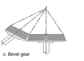
The gears or toothed wheels may be classified as follows:
- Parallel
b. Intersecting

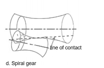
c. Non intersecting and non-parallel
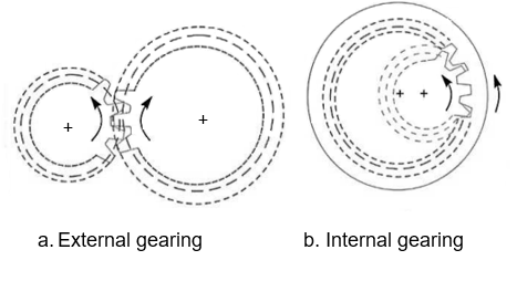
2. According to the type of gearing.
b. Internal gearing
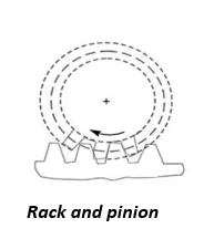
c. Rack and pinion
3. According to the position of teeth on the gear surface


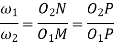
Mathematically,
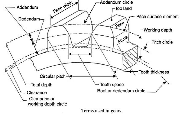
Circular pitch. 
D=diameter of the pitch Circle, and
T= number of teeth on the wheel
It is denoted by 
Mathematically,
Diametral pitch 
T=number of teeth
D=pitch circle diameter
Module m=D/T


 ………. I
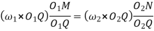
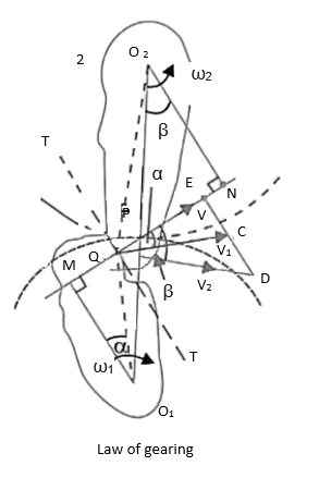
Also, from similar triangles 
 ……….. II
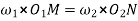
Combining equations, I and II we have

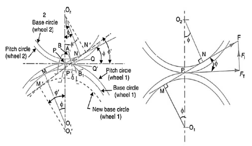
Involute teeth:-


From similar triangles 
Which determines the ratio of the radii of the two base circles. The radii of the base circles are given by

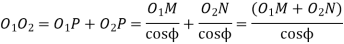
Also, the centre distance between the base circles,

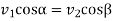
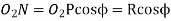
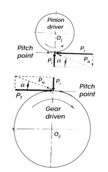
If F is the maximum tooth pressure as shown in figure then
Tangential force 
Radial or normal force 
The torque exerted on the gear shaft
=  where r is the pitch circle radius of the gear.
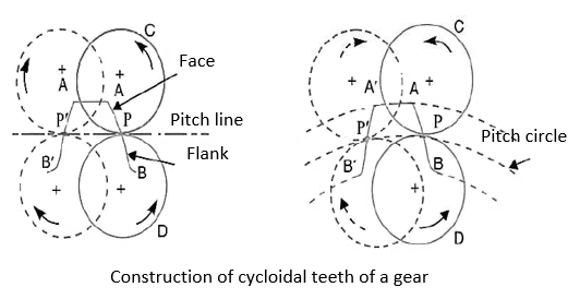
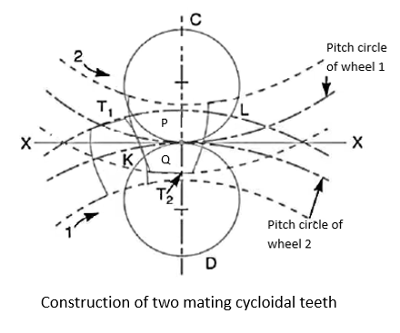
Cycloidal teeth


Sr No. | Cycloidal teeth | Involute teeth |
1 | Pressure angle varies from maximum at the beginning of engagement, reduces to zero at the pitch and again increases to maximum at the end of engagement resulting in less smooth running of the gears. | Pressure angle is constant throughout the engagement of teeth. This results in smooth running of the gears. |
2 | It involves double curve for the teeth, epicycloid and hypocycloid. This complicates the manufacture. | It involves single curve for the teeth resulting simplicity of manufacturing and tools. |
3 | Owing to difficulty of manufacture these are costlier | These are simple to manufacture and thus cheaper. |
4 | Exact centre distance is required to transmit a constant velocity ratio | A little variation in the centre distance does not affect the velocity ratio |
5 | Phenomenon of interference does not occur at all | Interference can occur if the condition of minimum number of teeth on a gear is not followed |
6 | The teeth have spreading flanks and thus are stronger | The teeth have radial flanks and thus are weaker as compared to the cycloidal form for the same pitch. |
7 | In this, convex flank always has contact with a concave face resulting in less wear | Two convex surfaces are in contact and do there is more wear. |
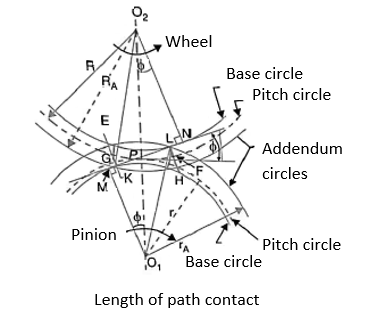
Let.  radius of addendum circle of pinion.
 radius of addendum circle of wheel.
 = radius of pitch Circle of pinion, and
 radius of pitch Circle of wheel.
From figure, we find that radius of the base circle of pinion
And radius of the base circle of wheel,
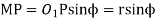
Now from right angle triangle 

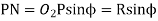
Length of the part of the path of contact, or the path of approach,

Similarly, from right-angled triangle 
And 
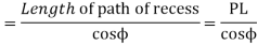
Length of the part of the path of contact, or path of recess

Length of the path of contact,


We know that the angle of the arc of approach
And the length of the arc of recess
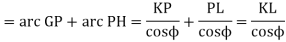
Since the length of the arc of contact GPH is equal to the sum of the length of the arc of approach and arc of recess, therefore,
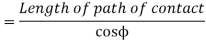
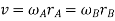
Length of the arc of contact

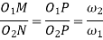
Where  =Angular velocity of the driver.
 =Angular velocity of the driven


Mathematically,
Contact ratio of number of pairs of teeth in contact
Where. 
m = module


Maximum length of path of approach,

And maximum length of path of recess,

Maximum length of path of contact

Maximum length of Arc of contact
Undercutting
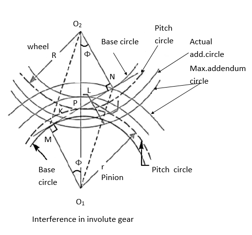
In general, there are three different ways of reducing or eliminating interference and subsequent undercutting at the flank region, when a pinion has less than minimum number of teeth to avoid interference.

2. By modifying addendum of gear tooth
3. Increased centre distance


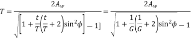
Minimum number of teeth on the pinion in order to avoid interference
Let. t= number of teeth on the pinion.
T= number of teeth on the wheel
m = module of the teeth
r= pitch Circle radius of pinion =m.t/2
G= Gear ratio =T/t =R/r
 = Pressure angle or angle of obliquity

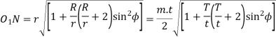
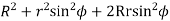
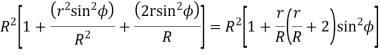
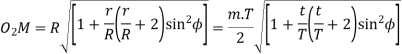
From triangle 


Where 
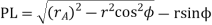
Limiting radius of the pinion addendum circle,
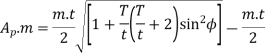
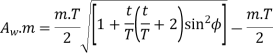
Let  = addendum of the pinion, where
  is a fraction by which the standard addendum of one module for the pinion should be multiplied in order to avoid interference.
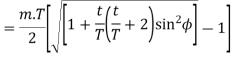
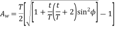
We know that the addendum of the pinion.

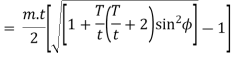
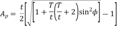
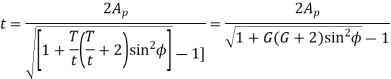
This equation gives the minimum number of teeth required on the pinion in order to avoid interference.
Minimum number of teeth on the Wheel in order to avoid interference
Let. T= minimum number of teeth required on the wheel in order to interference,
 .m= addendum of the wheel, where
  is a fraction by which the standard addendum for the wheel should be multiplied.
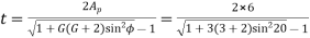
Using the same notations as in above article we have from triangle 

=
Where 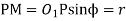
=
Limiting radius of wheel addendum circle
We know that addendum of the wheel


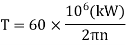
Where T = torque transmitted by gears
kW = power transmitted by gears
n= speed of rotation
The tangential component  acts at the pitch Circle radius. Therefore,

Or 
From figure 
The resultant force  is given by
The above analysis of gear tooth force is based on the following assumptions

(1) gear scuffing failures due to excessive heat generation and gear contact fatigue lives and associated failure modes of spalling and micro-pitting
(2) load-dependent (mechanical) gear mesh power losses, and
(3) a class of gear vibrations along the direction of the relative sliding and the damping effects along the line of action.
Following methods are used to reduce gear friction.
2. Lower speeds and loads.
3. Lubrication.
4. Material selection.
Numerical :
Solution Given. T=t=40;  = 20° ; m=6mm
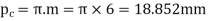
Circular pitch,
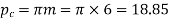 mm
mm
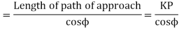
Length of Arc of contact

And length of path of contact
= Length of Arc of contact × cos = 33 cos 20° = 31mm
Let.  radius of the addendum circle of each wheel.
Pitch Circle radii of each wheel,
R =r= m.T/2=6×40/2=120mm
And length of path of contact

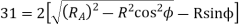
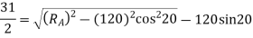
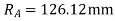
The addendum of the wheel
=  mm
mm
2. The following data relate to a pair of 20-degree involute gears in mesh:
Module=6mm, number of teeth on pinion =17, number of teeth on gear=49 addendum on pinion and gear wheel=1module
Find: 1. The number of pairs of teeth in contact 2. The angle turned through by the pinion and the gear wheel when one pair of teeth is in contact, and 3. The ratio of sliding to rolling motion when the tip of a tooth on the larger wheel a. Is just making contact, b. Is just leaving contact with its matting tooth, c. Is at the pitch point.
Solution
Given  =20° m=6mm; t=17 ; T=49 ; Addenda on pinion and gear wheel =1 module =6mm
Pitch Circle radius of pinion
r = m.t/2=6×17/2=51mm
And pitch Circle radius of gear
R = m.T/2=6×49/2=147mm
Radius of addendum circle of pinion
 addendum=51+6=57mm
And radius of addendum circle of gear
 addendum=147+6=153mm
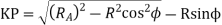
The length of path of approach


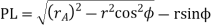
The length of path of recess


= 13.41mm
Length of path of contact
KL = KP + PL =15.5+13.41=28.91mm
Length of Arc of contact = 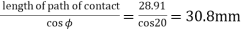
Circular pitch,
Number of pairs of teeth in contact
=Length of Arc of contact/circular pitch=30.8/18.852=1.6 say 2
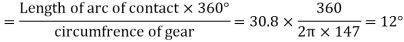
Angle turned through by the pinion
=
And angle turned through by the gear wheel
Ratio of sliding to rolling motion
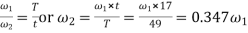
Let  =Angular velocity of pinion
 =Angular velocity of gear wheel
Rolling velocity 

Ratio of sliding velocity to rolling velocity
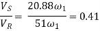
b. At instant when the tip of a tooth on the larger wheel is just leaving contact with its mating teeth, the sliding velocity.

Ratio of sliding velocity to rolling velocity
b. Since at the pitch point, the sliding velocity is zero, therefore the ratio of sliding velocity to rolling velocity is zero.
3. Two mating gears have 20 and 40 involute teeth of module 10 mm and 20° pressure angle. The addendum on each wheel is to be made of such length that the line of contact on each side of the pitch point has half the maximum possible length. Determine the addendum height for each gear wheel, length of the path of contact, arc of contact and contact ratio.
Solution Given t=20; T=40; m=10mm;  =20°
=20°
Addendum height for each gear wheel
The pitch Circle radius of the smaller gear wheel,
R = m.t/2 =10×20/2=100mm
And pitch circle radius of the larger gear wheel,
R = m.T/2 =10×40/2=200mm
 = radius of addendum circle for the larger gear wheel, and
 =radius of addendum circle for the smaller gear wheel.
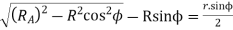
Since the addendum on each wheel is to be made of such a length that the line of contact on each side of the pitch point has half the maximum possible length, therefore
Path of approach, 
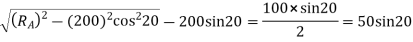

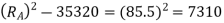

Addendum height for larger gear wheel

Now the path of recess 

Addendum height for smaller gear wheel

The length of the path of contact

=
The length of the arc of contact
 mm
mm
Circular pitch 
Contact ratio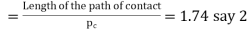
4. Two 20-degree involute spur gear mesh externally and give a velocity ratio of 3. The module is 3 mm and the addendum is equal to 1.1 module. If the pinion rotates at 120 RPM, determine the
Solution 
 VR=3 Addendum=1.1m m=3mm
Taking the higher whole number divisible by the velocity ratio,
T=51 and t=51/3=17
Pitch Circle radius of pinion
r = m.t/2= 3×17/2=25.5mm
And pitch Circle radius of gear
R = m.T/2= 3×51/2= 76.5 mm
Radius of addendum circle of pinion
 addendum = 25.5 + 1.1 x 3 = 28.8mm
And radius of addendum circle of gear
 addendum= 76.5 + 1.1 x 3 = 79.8 mm
The length of path of approach
 = 8.48 mm
The length of path of recess

= 7.25 mm
Length of path of contact
KL = KP + PL =8.48 + 7.25 = 15.73 mm
Length of Arc of contact = 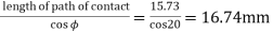
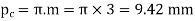
Circular pitch,
Number of pairs of teeth in contact
=Length of Arc of contact/circular pitch= 16.74/9.42=1.78 say 2
5. Two gears wheels Mahesh externally and are to give a velocity ratio of 3 to 1. The teeth are of involute form module =6 mm, addendum = one module, pressure angle = 20° . The pinion rotates at 90 r.p.m. determine 1. The number of teeth on the pinion to avoid interference on it and the corresponding number of teeth on the wheel. 2. The length of path and arc of contact,. 3. The number of pairs of teeth in contact. 4. The maximum velocity of sliding
Solution :- Given G=T/t =3, m=6mm,  x module = 6mm;
  =20°
=20°
 or
or  =2π×90/60=9.43rad/s
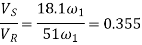
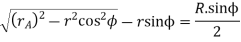
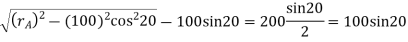
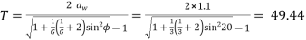
Number of teeth on the pinion to avoid interference,
 = 18.2 say 19
And corresponding number of teeth on the wheel,
T=G.t=3 x 19=57
Pitch Circle radius of pinion,
r = m.t/2=6×19/2= 57mm
Radius of addendum circle of pinion

And pitch Circle radius of wheel,
R= m.T/2 =6×57/2=171mm
Radius of addendum circle of wheel.
 = R+ addendum on wheel=171+6=177mm
We know that the path of approach

= 
And the path of recess

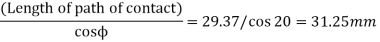
Length of path of contact
KL= KP + PL = 15.7+13.67=29.37mm
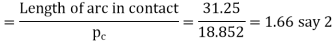
We know that length of Arc of contact
We know that circular pitch

Number of pairs of teeth in contact
Let  =Angular speed of wheel in rad/s
We know that 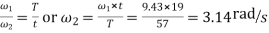
Maximum velocity of sliding
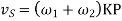
= (9.43+3.14) 15.7 = 197.35mm/s
1. Ghosh Malik, Theory of Mechanism and Machines, East-West Pvt. Ltd.
2. Hannah and Stephans, Mechanics of Machines, Edward Arnolde Publication.
3. R L Norton, Kinematics and Dynamics of Machinery, First Edition, McGraw Hill Education
(India) P Ltd. New Delhi
4. Sadhu Singh, Theory of Machines, Pearson
5. D.K. Pal, S.K. Basu, Design of Machine Tools, Oxford & Ibh Publishing Co Pvt. Ltd.
6. Dr. V. P. Singh, Theory of Machine, Dhanpatrai and sons.
7. C. S. Sharma & Kamlesh Purohit, “Theory of Machine and Mechanism”, PHI.


