Unit -3
Gear Trains
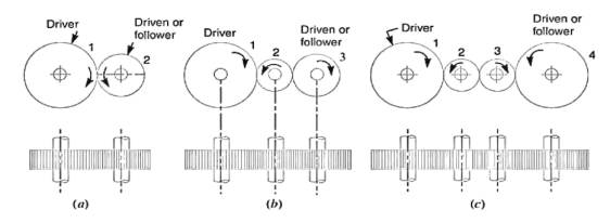
Following are the different types of gear trains, depending upon the arrangement of wheels:
Let  =speed of gear 1 in r.p.m
 =speed of Gear 2 in r.p.m.
 =number of teeth on gear 1 and
 = number of teeth on gear 2.
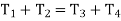
Speed ratio=
Train value=
Let  = speed of driver in RPM
 =speed of intermediate gear in RPM
 = speed of driven or follower in r.p.m
 = number of teeth on driver
 = number of teeth on the intermediate gear
 = number of teeth on driven or follower
speed ratio =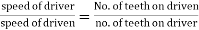
Train value=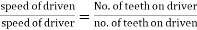
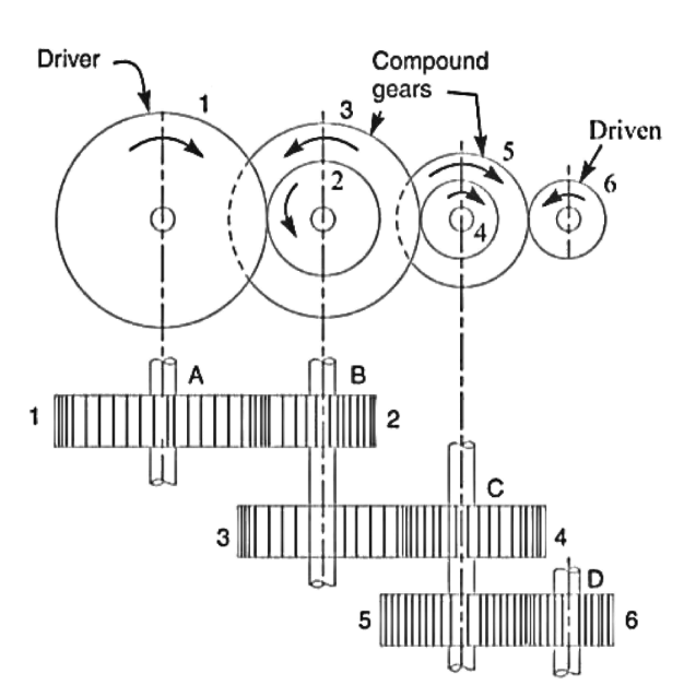
2. Compound gear train

Let  =speed of driving gear 1.
 = number of teeth on driving gear 1.
 = speed of respective gears in RPM
 = number of teeth on respective gears.
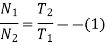
Since gear 1 is in mesh with Gear 2, therefore, its speed ratio is
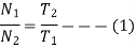
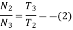
Similarly for Gear 3 and 4-speed ratio is
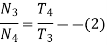
And for gears 5 and 6-speed ratio is
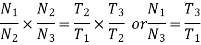
The speed ratio of the compound gear train is obtained by multiplying the equations 1 2 and 3
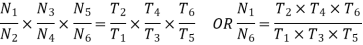
Speed ratio= 
Train value=
3. Reverted gear train
Let  =number of teeth on gear 1
 = pitch Circle radius of gear 1, and
 = speed of gear 1 in RPM
Similarly,
 =number of teeth on respective gears,
 = pitch Circle radius of respective gears and
 = speed of respective gears in RPM
Since the distance between the centers of shafts of gear 1 and 2 as well as Gear 3 and 4 is the same common therefore
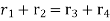 …….. i
also, the circular pitch or module of all the gear is assumed to be the same, therefore number of teeth on each gear is directly proportional to its circumference to the radius.
 ……….. ii
And
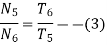
speed ratio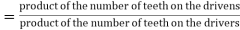
Or  ……….iii
4. Epicyclic gear train


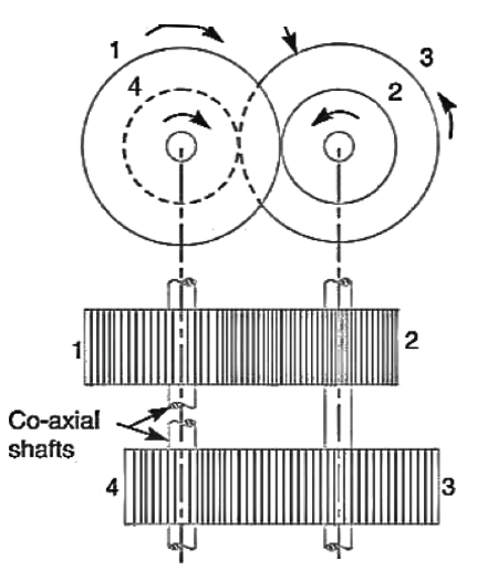
The following two methods may be used for finding out the velocity ratio of an epicyclic gear train.
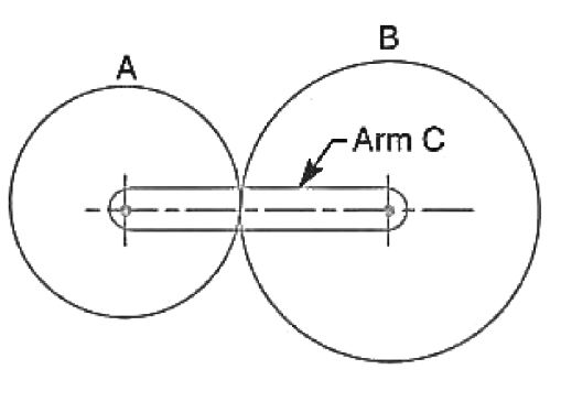
Let  = number of teeth on gear A, and
 = number of teeth on gear B.


Step No. | Conditions of motion | Arm C | Gear A | Gear B |
1 | Arm fixed gear A rotates through plus one revolution | 0 | +1 |
|
2 | Arm fixed gear A rotates through +x revolutions | 0 | +x |
|
3 | Add +y revolutions to all elements | +y | +y | +y |
4 | Total motion | +y | x+y |
|


2. Algebraic method:-

And speed off the gear B relative to the arm C,

Since the gears A and B are meshing directly, therefore they will revolve in opposite directions.
Since the arm c is fixed, therefore its speed. 

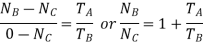
If the gear A is fixed, then 
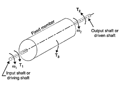
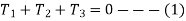

Where  are the corresponding externally applied forces at radii


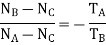
But for a fixed member 

Step No. | Conditions of motion | Arm | Gear D | Compound gear B-C | Gear A |
1 | Arm fixed- gear D rotates through plus one revolution | 0 | +1 |
|
|
2 | Arm fixed -gear D rotates through +x revolutions | 0 | +x |
|
|
3 | Add +y revolutions to all elements | +y | +y | +y |
|
4 | Total motion | +y | x+y |
|
|


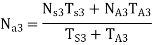
Speed of arm
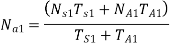


As is integral with
Thus  can be known.
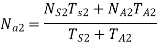
In the same way,
 is integral with
So  can be calculated.
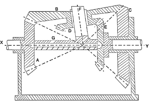
Humpage's speed reduction gear.
Numericals
Given 
Step No. | Conditions of motion | Arm C | Gear A | Gear B |
1 | Arm fixed gear A rotates through plus one revolution | 0 | +1 |
|
2 | Arm fixed gear A rotates through +x revolutions | 0 | +x |
|
3 | Add +y revolutions 2 all elements | +y | +y | +y |
4 | Total motion | +y | x+y |
|


Speed of gear B when gear A is fixed
Since the speed of arm is 150 r.p.m. anticlockwise, therefore from the fourth row of the table,
Y=+150 r.p.m
Also, the gear is fixed, therefore
x+y=0 or x=-y= -150r.p.m.
Speed of gear B 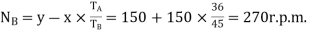
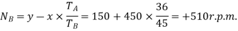
Speed of gear B when gear A makes 300 rpm clockwise
Since the gear A makes 3000r.p.m. clockwise, therefore from the fourth row of the table,
x+y=-300. Or x =-300 - y = -300-150= - 450r.p.m
Speed of gear B,
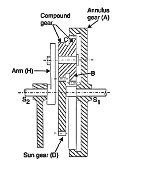
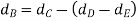
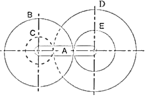
2. An internal wheel B with 80 teeth is keyed to a shaft F. A fixed internal wheel C with 82 teeth is concentric with B. A compound wheel D-E gears with the two internal wheels: D has 28 teeth and gears with C while E gears with B. The compound wheels revolve freely on a pin which projects from a disc keyed to a shaft. A coaxial with F if the wheels have the same pitch and the shaft A makes 800 r.p.m. what is the speed of the shaft F? Sketch the arrangement.
Solution 
The arrangement is shown in figure
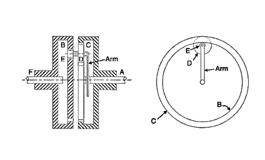
Let  be the pitch circle diameter of wheels B, C, D, and E respectively. From the geometry of the figure,
Since the number of teeth is proportional to their pitch circle diameter for the same pitch, therefore

The table of motions is given below
Step No. | Conditions of motion | Arm (or shaft A) | Wheel B (or shaft F) | Compound gear D-E | Wheel C |
1 | Arm fixed – wheel B rotated through +1 revolution anticlockwise | 0 | +1 |
|
|
2 | Arm fixed-wheel B rotated through +x revolutions | 0 | +x |
|
|
3 | Add +y revolutions to all elements | +y | +y | +y | +y |
4 | Total motion | +y | x+y |
|
|


Since the wheel, C is fixed, therefore from the fourth row of the table,
 or
or 
the shaft A makes 800 r.p.m. therefore from the fourth row of the table,
y=800----(2)
From equations 1 and 2
x=-762
Speed of shaft F= speed of wheel B=x+y =-762+800=+38r.p.m.
=38 r.p.m.anticlockwise
3. In a reverted epicyclic gear train, the arm A carries two gears B and C and compound gear D-E. The gear B meshes with gear E and the gear C meshes with gear D. The number of teeth on gears B, C, and D are 75, 30, and 90 respectively. Find the speed and direction of gear C when gear B is fixed and the arm A makes 100 r.p.m. clockwise.
Given 
Let 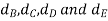 the pitch circle diameter of gear B, C, D, and E respectively. From the geometry of the figure
Since the number of teeth on each gear, for the same module, are proportional to their pitch circle diameter therefore

The table of motions is drawn as follows:
Step No. | Conditions of motion | Arm (or shaft A) | Wheel B (or shaft F) | Compound gear D-E | Wheel C |
1 | Arm fixed – compound gear D-E rotated through +1 revolution anticlockwise | 0 | +1 |
|
|
2 | Arm fixed-compound gear D-E rotated through +x revolutions | 0 | +x |
|
|
3 | Add +y revolutions to all elements | +y | +y | +y | +y |
4 | Total motion | +y | x+y |
|
|


Since the gear B is fixed, therefore from the fourth row of the table
 or
or 
y - 0.6=0---(1)
Also, the arm A makes 100 r.p.m. clockwise, therefore
y= -100---(2)
Substituting above value in equation 1 we get
- 100 - 0.6x = 0. Or x=-100/0.6=-166.67
From the fourth row of the table, speed of gear C
 =400 r.p.m. anticlockwise.
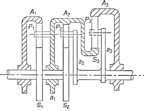
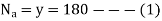
4. The annulus A in the gear shown in figure rotates at 300 r.p.m. about the axis of the fixed wheel S which has 80 teeth. The three-armed spider is driven at 180 rpm. Determine the number of teeth required on the wheel P.
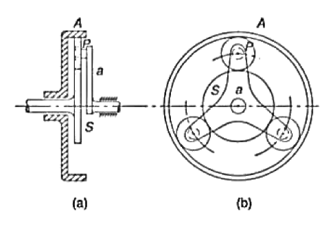
Solution 
Step No. | Conditions of motion | Arm a | Gear S | Gear P | Gear A |
1 | Arm a fixed – gear S rotated through +1 revolution anticlockwise | 0 | +1 |
|
|
2 | Arm a fixed – gear S rotated through +x revolution anticlockwise | 0 | +x |
|
|
3 | Add +y revolutions to all elements | +y | +y | +y | +y |
4 | Total motion | +y | x+y |
|
|

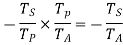


From given conditions,

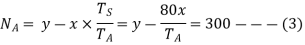
From 1 and 2 x= -y= -180
Solving 3
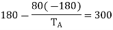
Or 

The pitch diameters of the wheels are proportional to the number of teeth on them.

Or  or
or 
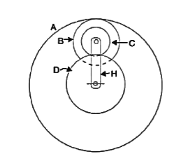
5. An epicyclic gear train consists of sun wheel S, a stationary internal gear E and three identical planet wheels P carried on a star-shaped planet carrier C. The size of different tooth wheels are such that the planet carrier C rotates at 1/5th of the speed of the sun wheel S. The minimum number of teeth on any wheel is 16. The driving torque on the sun wheel is 100N-m. Determine
Solution Given 
The arrangement of the epicyclic gear train is shown in the figure.
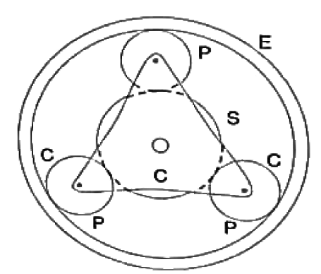
Let  be the number of teeth on the sun wheel S and the internal gear E respectively. The table of motions is given below:
Step No. | Conditions of motion | Arm (or shaft A) | Wheel B (or shaft F) | Compound gear D-E | Wheel C |
1 | Planet carrier C fixed, sun wheel S rotates through +1 revolution anticlockwise | 0 | +1 |
|
|
2 | Planet carrier C fixed, sun wheel S rotated through +x revolutions | 0 | +x |
|
|
3 | Add +y revolutions to all elements | +y | +y | +y | +y |
4 | Total motion | +y | x+y |
|
|


We know that when the sun wheel as makes 5 revolutions, the planet carrier C makes one revolution therefore from the fourth row of the table
y=1 and. x+y =5 or x= 5 – y = 5 – 1 = 4
Since the gear E is stationary, therefore from the fourth row of the table.

Since the minimum number of teeth on any wheel is 16, therefore, let us take the number of teeth on the sun wheel, 

Let  be the pitch circle diameter of the wheel S, P, and E respectively. Now from the geometry of the figure

assuming the module of all the gears to be same, the number of teeth are proportional to their pitch circle diameter,

2. Torque necessary to keep the internal gear stationary
Torque on S ×Angular speed of S = torque on C ×Angular speed of C
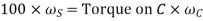
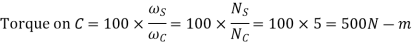
Torque necessary to keep the internal gear stationary
=500-100=400N-m
6. In the epicyclic gear train, as shown in the figure, the driving gear A rotating in clockwise direction has 14 teeth and the fixed annular gear C has 100 teeth. The ratio of teeth in gears E and D is 98: 41. If 1.85 kW is supplied to the gear A rotating at 1200 r.p.m. find
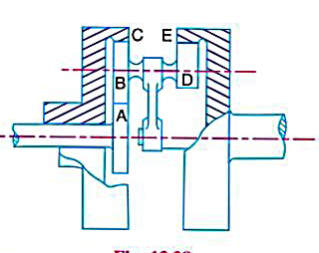
Solution Given. 
Let  the pitch circle diameter of gear A, B, and C respectively. From figure

Since teeth of all gears have the same pitch and the number of teeth is proportional to their pitch circle diameters, therefore
The table of motions is not drawn as below:
Step No. | Conditions of motion | Arm | Gear A | Compound gear B-D | Gear C | Gear E |
1 | Arm fixed-Gear A rotates through -1 revolution clockwise | 0 | -1 |
|
|
|
2 | Arm fixed-Gear A rotated through +x revolutions | 0 | -x |
|
|
|
3 | Add -y revolutions to all elements | -y | -y | -y | -y | -y |
4 | Total motion | -y | -y-x | - |
|
|


Since the annular gear, C is fixed, therefore from the fourth row of the table,
 or
or 
-y + 0.14x = 0 —(1)
Also, the gear A is rotating at 1200 r.p.m. therefore
- x – y = 1200--------- (2)
From equation 1 and 2
X=-1052.6 and y=-147.4
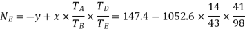
=4 r.p.m. anticlockwise
2. Fixing torque required at C
We know that torque on A =
Since the efficiency is 100 percent throughout therefore the power available at E will be equal to power supplied at A
Torque on E=
Fixing Torque required at C
=4416-14.7=4401.3N-m
Reference:


