Back to Study material
TOM2

Unit - 4

Cam and Follower


Types of cams

Cams are classified according to
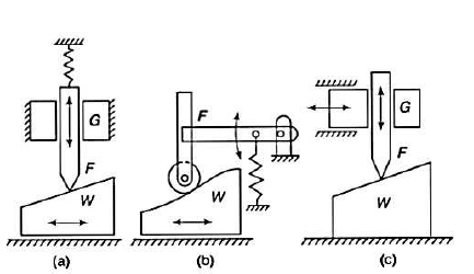
  • According to shape
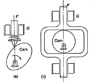
  • Wedge and flat cams
  • A wedge cam has a wedge W which, in general, has a translational motion.
  • The follower F can either translate or oscillate.
  • A spring is, usually, used to maintain the contact between the cam and the follower.
  •  In figure the cam is stationary, and the follower constraint or guide G causes the relative motion of the cam and the follower.
  •  

    2.     Radial or disc cams

  • Cam in which the follower moves radially from the centre of rotation of the cam is known as a radial or a disc cam.
  • Radial cams are very popular due to their simplicity and compactness.
  •  


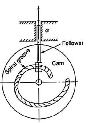
    3.     Spiral cams

  • Spiral cam is a face cam in which a groove is cut in the form of a spiral as shown in figure.
  • The spiral groove consists of teeth which mesh with a pin gear follower.
  • The velocity of the follower is proportional to the radial distance of the groove from the axis of the cam.
  • The use of such cam is limited as the cam has to reverse the direction to reset the position of the follower.
  • It find it use in computers.
  •  

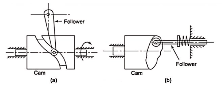
    4.     Cylindrical cams

  • In a cylindrical cam, a cylinder which has a circumferential contour cut in the surface, rotates about its axis.
  • The follower motion can be of two types as follows:
  • In the first type, a groove is cut on the surface of the cam and roller follower has a constraint oscillating motion.
  • Another type is an end cam in which the end of the cylinder is the working surface.
  • Spring loaded follower translates along or parallel to the axis of the rotating cylinder.
  • Cylindrical cams are also known as barrel or drum cams.
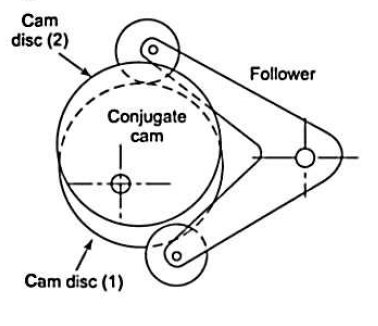
  • 5.     Conjugate cams:-

  • Conjugate cam is a double disc cam, the two discs being keyed together and are in constant touch with the two rollers of a follower.
  • Thus, the follower has a positive constraint.
  • Such type of cam is preferred when the requirements are low wear, low noise, better control of the following, high speed, high dynamic loads, etc.
  • 6.     Globoidal cams

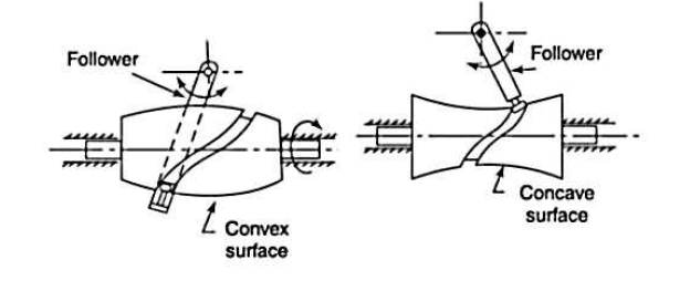
  • A globoidal cams have two types of surfaces, convex or concave.
  • A circumferential contour is cut on the surface of rotation of the cam to impart motion to the follower which has an oscillatory motion.
  • The application of such camps is limited to moderate speed and where the angle of oscillation of the follower is large.
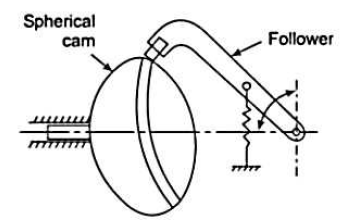
  • 7.     Spherical cams

  • A spherical cam, the follower oscillates about an axis perpendicular to the axis of rotation of the cam.
  • The follower oscillates about an axis parallel to the axis of rotation of the cam.
  • A spherical cam is in the form of a spherical surface which transmits motion to the follower.
  •  

    b.    According to follower movement

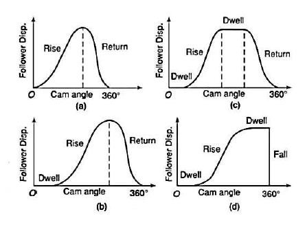
    The motions of the followers are distinguished from each other by the dwells they have.

  • Rise return rise ( R-R-R)
  • In this, there is alternate rise and return of the following with no periods of dwells.
  • Its use is very limited in the industry.
  • The follower has a linear or an angular displacement.
  •  

    2.     Dwell rise return dwell (D-R-R-D)

  • In such type of CAM, there is a rise and return of the follower after a dwell.
  • This type is used more frequently than the R-R-R type of cam.
  • 3.     Dwell rise dwell return dwell (D-R-D-R-D)

  • It is the most widely used type of CAM.
  • The dwelling of the cam is followed by the rise and dwell and subsequently by return and dwell as shown in figure.
  • In case the return of the follower is by a fall, the motion maybe known as well as Dwell-Rise-Dwell.
  • Classification of followers

    The followers may be classified as discussed below:

  • According to the surface in contact. The followers according to the surface in contact, are as follows:
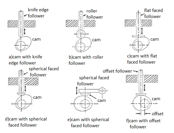
    1. Knife edge follower:
  • When the contacting end of the follower has a sharp knife edge, it is called a knife edge follower, as shown in figure.
  • The sliding motion takes place between the contacting surfaces.
  • It is rarely used in practice because the small area of contacting surface results in excessive where.
  • In knife edge followers, a considerable side thrust exist between the follower and the guide.
  •  

    2.     Roller follower:

  • When the contacting and of the following is a roller, it is called a roller follower, as shown in figure.
  • Since the rolling motion takes place between the contacting surfaces, therefore the rate of ware is greatly reduced.
  • In roller followers also the side thrust exist between the follower and the guide.
  • The roller followers are extensively used where more space is available such as in stationary gas and oil engines and aircraft engines.
  •  

    3.     Flat faced or mushroom follower:-

  • When the contacting and of the following is a perfectly flat face, it is called a flat faced follower, as shown in figure.
  • It may be noted that the side thrust between the follower and the guide is much reduced in case of flat faced followers.
  • The only side thrust is due to friction between the contact surfaces of the follower and the camp.
  • The flat faced followers are generally used where space is limited such as in cams which operate the valves of automobile engines.
  •  

    4.     Spherical faced follower :-

  • When the contacting end of the follower is of spherical shape, it is called a spherical faced follower, as shown in figure.
  • It may be noted that when a flat faced follower is used in automobile engines, high surface stresses are produced.
  • In order to minimise the stresses, the flat end of the follower is machine to a spherical shape.
  •  


    b.     According to the motion of the follower the followers, according to its motion are of the following two types

  • Reciprocating for translating follower
  • When the follower reciprocates in guides as the cam rotates uniformly, it is known as reciprocating or translating follower.
  • The followers as shown in figure a to f are all reciprocating or translating followers.
  •  

    2.     Oscillating or rotating follower

  • When the uniform rotary motion of the cam is converted into predetermined oscillatory motion of the follower, it is called oscillating for rotating follower.
  • The follower, as shown in figure is an oscillating or rotating follower.
  •  

    c.      According to the path of motion of the follower.  The followers, according to its path of motion are of the following two types

  • Radial follower:-
  • When the motion of the follower is along an axis passing through the centre of the cam, it is known as radial follower.
  • The followers, as shown in figure a to e are all radial followers.
  •  

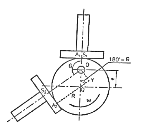
    2.     Offset follower:-

  • When the motion of the follower is along an axis away from the axis of the cam centre, it is called offset follower.
  • The follower, as shown in figure (f) is an off-set follower.
  •  


    1. Displacement, velocity and acceleration diagrams when the follower moves with uniform velocity
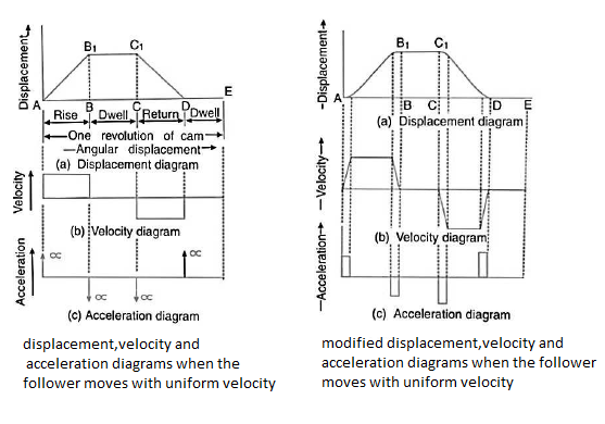
  • The displacement, velocity and acceleration diagrams when a knife edge follower moves with uniform velocity as shown in figure a ,b and c respectively.
  • The abscissa represents the time may represent the angular displacement of the cam in degrees.
  • The ordinate represents the displacement or velocity or acceleration of the follower.
  • Since the follower moves with uniform velocity during its rise and return stroke, therefore the slope of the displacement curves must be constant.
  • In other words,
    must be straight lines.
  • The followier remains at rest during part of the cam rotation.
  • The periods during which the follower remains at rest are known as dwell periods, as shown by lines
    in figure a .
  • From figure c we see that the acceleration or retardation of the follower at the beginning and at the end of each stroke is infinite.
  • This is due to the fact that the follower is required to start from rest and has to gain a velocity within no time.
  • This is only possible if the acceleration or retardation at the beginning and at the end of each stroke is infinite. These conditions are however impracticable.
  • In order to have the acceleration and retardation within the finite limits, it is necessary to modify the conditions which govern the motion of the followers.
  • This may be done by rounding of the sharp corners of the displacement diagram at the beginning and at the end of each stroke, as shown in figure a.
  • By doing so the velocity of the follower increases gradually to its maximum value at the beginning of each stroke and decreases gradually to zero  at the end of each stroke as shown in figure b .
  • The modified displacement, velocity and acceleration diagrams are shown in figure.
  • The round corners of displacement diagram are usually parabolic curve because the parabolic motion results in a very low acceleration of the follower for a given stroke and cam speed.
  • 2. Displacement, velocity and acceleration diagrams when the follower moves with simple harmonic motion
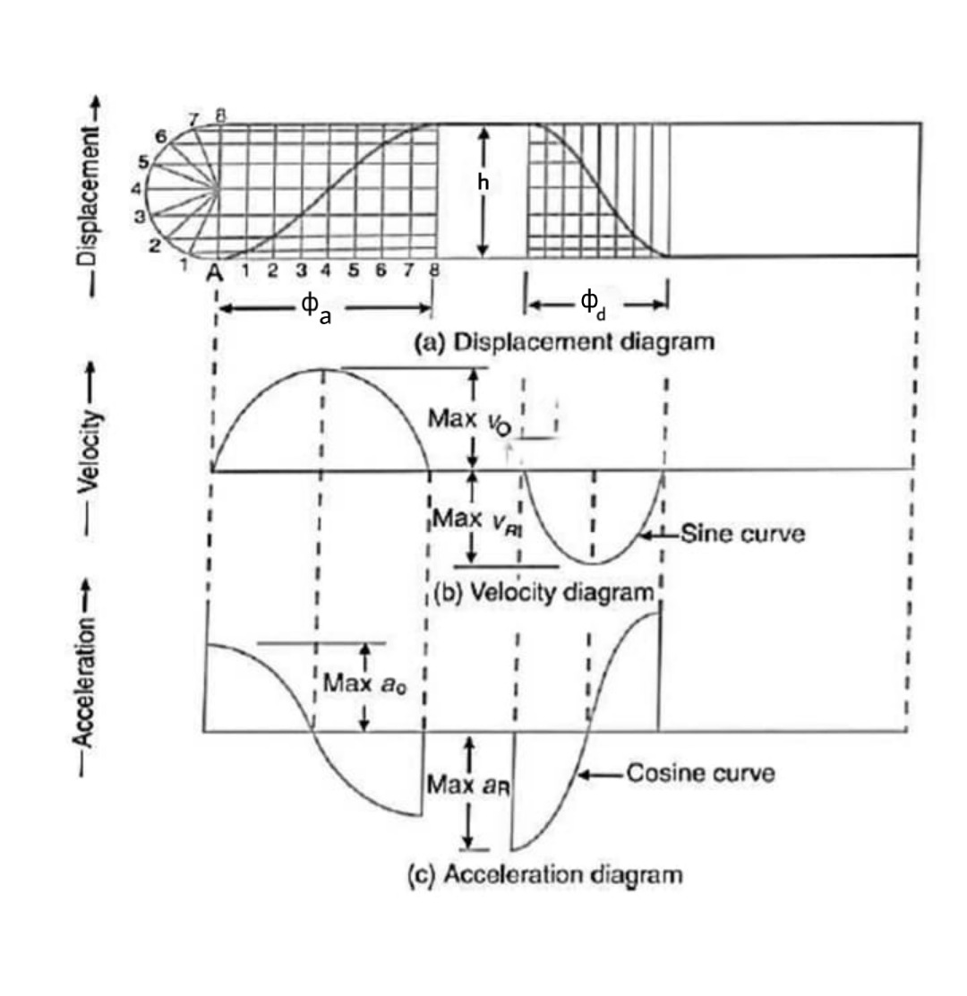
  • The displacement velocity and acceleration diagrams when the follower moves with simple harmonic motion are shown in figure a b  and c respectively.
  • The displacement diagram is drawn as follows:
  • Draw semicircle on the follower stroke as diameter.
  • Divide the semicircle into any number of even equal parts.
  • Divide the angular displacement of the cam during out stroke and return stroke into the same number of equal parts.
  • The displacement diagram is obtained by projecting the points as shown in figure a.
  • The velocity and acceleration diagrams are shown in figure b and c respectively.
  • Since the follower moves with a simple harmonic motion, therefore velocity diagram consists of a sine curve and the acceleration diagram is a cosine curve.
  • We see from figure that the velocity of the follower is zero at the beginning and at the end of its stroke and increases gradually to a maximum at mid stroke.
  • On the other hand, the acceleration of the follower is maximum at the beginning and at the ends of the stroke and diminishes to zero at mid stroke.
  • Let    h =stroke of the follower,

                  =angular displacement of the cam during out stroke and return stroke of the follower respectively, in radian, and

                = Angular velocity of the cam in radian/s

    Maximum velocity of the follower on the outstroke

    Maximum acceleration of the follower on the out stroke.

    Similarly, maximum velocity of the follower on the return stroke.

    And maximum acceleration of the follower on the return stroke.

    3.     Displacement, velocity and acceleration diagrams when the follower moves with uniform acceleration and retardation
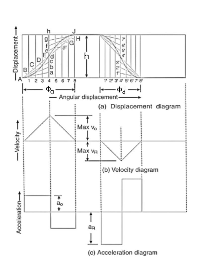
  • The displacement, velocity and acceleration diagrams when the follower moves with uniform acceleration and retardation are shown in figure a b and c respectively.
  • The displacement diagram consists of a parabolic curve and may be drawn as discussed below:
  • Divide the angular displacement of the cam during outstroke into any even number of equal parts and draw vertical lines through these points as shown in figure a.
  • Divide the stroke of the follower into the same number of equal even parts.
  • Join Aa to intersect the vertical line through point 1 at B. Similarly, obtained another points C ,D etc. As shown in figure a. Now join these points to obtain the parabolic curve for the outstroke of the follower.
  • In the similar way as discussed above, the displacement diagram for the follower during return stroke may be drawn.
  • Since the acceleration and retardation are uniform, therefore the velocity varies directly with the time. The velocity diagram is shown in figure b.
  • Let h=stroke of the follower.

             =angular displacement of the cam during out stroke and return stroke of the follower respectively, and

           = Angular velocity of the cam.

    Maximum velocity of the follower during outstroke,

    Similarly, maximum velocity of the following during return stroke,

  • We see from the acceleration diagram, as shown in figure c, that during first half of the outstroke there is uniform acceleration and during the second half of the outstroke there is a uniform retardation.
  • Thus, the maximum velocity of the follower is reached after the time
    (during out stroke) and
    (during return stroke).
  • Maximum acceleration of the follower of during out stroke,

    Similarly, maximum acceleration of the following during return stroke,

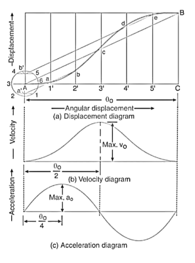
    4. Displacement, velocity and acceleration diagrams when the follower moves with cycloidal motion

  • The displacement, velocity and acceleration diagrams when the follower moves with cycloidal motion are shown in figure a b and c respectively.
  • We know that cycloidal is a curve traced by a point on a circle when the circle rolls without slipping on a straight line.
  • In case of cam, the straight line is a stroke of the follower, which is translating, and the circumference of the rolling circle is equal to the stroke of the follower. Therefore, the radius of the rolling circle is  S/2π.
  • The displacement diagram is drawn as discussed below:
  • Draw a circle of radius S/2π with A as centre.
  • Divide the circle into any number of equal even parts. Project these points horizontally on the vertical centre line of the circle. These points are shown by a' and b' in figure a
  • Divide the angular displacement of the cam during outstroke into the same number of equal even parts as the circle is divided. Draw vertical lines through these points.
  • Join AB which intersects the vertical line through 3' at c.
  • From a' draw a line parallel to AB  intersecting the vertical lines through 1’ and 2’ at a and b respectively.

    5.     Similarly, from b’ draw a line parallel to AB intersecting the vertical lines through 4’ to 5’ at d & e respectively.

    6.     Join the point A a b c d e B by a smooth curve. This is the required cycloidal curve for the following during outstroke.

    Let        = angle through which the cam rotates in time t seconds, and

               = Angular velocity of the cam.

    The velocity is maximum when

    Maximum velocity of the following during outstroke,

    Similarly, maximum velocity of the following during return stroke,

    Maximum acceleration of the following due to out stroke,

    Similarly, maximum acceleration of the following during return stroke,

  • The velocity and acceleration diagrams are shown in figure b and c respectively
  •  


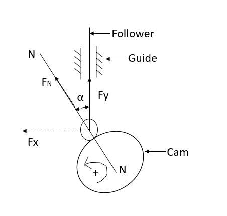
  • Pressure angle
      is defined as angle between line of stroke of follower and common normal drawn at contact point as shown.
  • As cam rotates, force is transmitted along the common normal .
  • This force
    can be resolved
  • Along the direction of follower motion
  • Perpendicular to the direction of follower motion
  • as
    which may cause Jamming of follower in its guides & failure of follower assembly.
  • Also, it is observed that if we select smaller value of  
    to avoid above problems,
  • Size of CAM increases.
  • Therefore, manufacturing cost increases
  • Inertia of CAM increases therefore it cannot be used for quick starting and stopping application.
  • As a matter of compromise, pressure angle for cam is selected as 30°
  • The pressure angle can be reduced by increasing prime circle radius.
  • The cam size is determined by considering two factors: the pressure angle and the minimum radius of the curvature..
  • Pressure angle for oscillating and translating roller follower radial cams are shown below.
  • For flat faced follower is the pressure is apparently zero at all times.
  • In force close cams, the pressure angle is important during the rise portion where cam is driving the following, in return motion it is the spring force that lowers the follower; hence the pressure angle is not that critical.
  • Using eccentricity, for the same cam size can reduce the pressure angle during the rise while there is some increase of pressure angle during the return, or for the same pressure angle a smaller cam size can be used.
  • In practice for roller followers it is common to determine the cam size using the maximum pressure angle criteria and then check that the cam curvature is satisfactory.
  • In case of flat faced follower, the cam curvature is the determining criteria for the cam size.
  • Undercutting

  • Sometimes, it may happen that the prime circle of a cam is proportioned to provide satisfactory pressure angle; still the follower may not be completing the desired motion.
  • This can happen if the curvature of the pitch curve is too sharp.
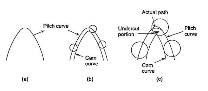
  • Figure a show the pitch Circle of a cam.
  • In figure b, a roller follower is shown generating this curve.
  • In figure c, a larger roller is shown trying to generate this curve.
  • It can easily be observed that the cam curve loops over itself in order to realize the profile of the pitch curve.
  •  As it is impossible to produce such a cam profile, the result is that the camp will be undercut and become a pointed cam.
  • Now when the roller follower will be made to move over this cam, it will not be producing the desired motion.
  • It may be observed that the camp will be pointed if the radius of the roller is equal to the radius of curvature of the pitch curve.
  • Thus, to have a minimum radius of curvature of the cam profile, the radius of curvature of the prime circle must always be greater than that of the radius of the roller.
  •  


  • In a cam follower system, the contact between the cam surface and follower is maintained by means of retaining spring.
  • Beyond the particular speed of CAM rotation, the follower may lose contact with the cam, because of inertia force acting on the follower.
  • The phenomenon is called as jump phenomenon.
  • When the follower re-establishes contact with the cam, it may do so with severe impact loads that can damage the surface of the cam and hammering noise can be heard at this jump Speed.
  • During the follower jump, transient vibrations are set up in the follower and these occur only with high speed, highly flexible cam follower system.
  • With jump, the cam and follower separate owing to excessively unbalanced forces exceeding the spring force during the period of negative acceleration.
  • This is undesirable since the fundamental function of the cam follower system; the constraint and control of follower motion are not maintained.
  • Also, the life of the cam flank surface reduces due to hammering action of follower on cam and hammering noise is generated which further results in vibrations of the system.
  • The jump phenomenon will be avoided by limiting the speed of CAM or by increasing stiffness of the retaining spring.
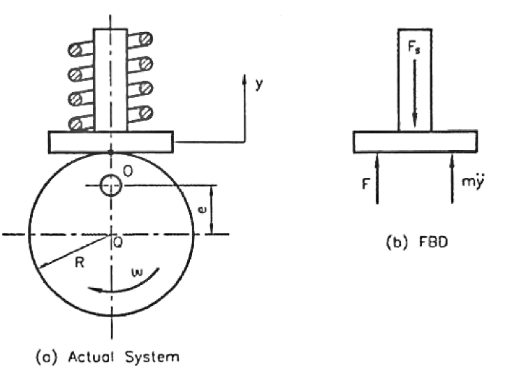
  • Figure shows an eccentric cam follower, which is analysed for jump phenomenon.
  • Lift of follower = y =

    Differentiating equation with respect to time t we get

    Velocity of follower =

    Differentiating equation with respect to time t, we get

    Acceleration of follower=

    Where cam angle turned from lowest position

  • Now consider the arrangement as shown in figure
  • Let m=mass of follower

         e=eccentricity

    k = stiffness of spring

    F = contact force between cam and follower

    = total spring force

    P = preload in spring

    =Angular speed of cam

    Then, from the free body diagram, we have

    Inertia force =  External forces

  • This contact force between cam and follower is maximum when
    and minimum when
    0 It is also dependent upon the square of CAM velocity.
  • When this contact force between cam and follower becomes negative, the follower would lose contact with the surface resulting in jump.
  • This would happen if the speed is increased beyond a particular critical speed
    (at
  • Where =jump speed

    Therefore, to avoid jump

    Or to avoid jump


  • In any class of machinery where automatic control and accurate timing are important, the cam is an indispensable part of mechanism.
  • Cam follower mechanism find application in a wide variety of devices and machines, such as printing presses, shoe machinery, textile machinery, automobile engines and pumping devices.
  • The cam follower mechanism is versatile and almost any arbitrarily specified motion can be achieved. The use of algebraic polynomials to specify the following motion is a new choice for cam profiles.
  • In which the differential equations of motion are solved using polynomial follower motion equations.
  • This class of motion function is highly versatile especially in high speed automobiles.
  • A 2-3 polynomial cam profile is cubic in nature and follower acceleration is discontinuous at the end points making it unsuitable at higher speeds.
  • 3-4-5 polynomial cam profile has 6 polynomial coefficient and a degree of 5, provides added control over follower acceleration at the end points
  • A 3-4-5 polynomial cam profile has an extended control as it provides a zero acceleration at the endpoints and no control over the follower jerks at
  • The 2-3 Polynomial D-R-D Cam

    In this type of cam curves, four boundary conditions are used to hence displacement equation is given by,

    ……1

    Boundary condition are

    Differentiating the above equation w.r.t to get velocity of follower

    Initially put boundary conditions in equation (1),

    Now put the boundary conditions in equation (2)

    Put in equation (3)

    ……. 5

    Solving equation (4) and (5) we get

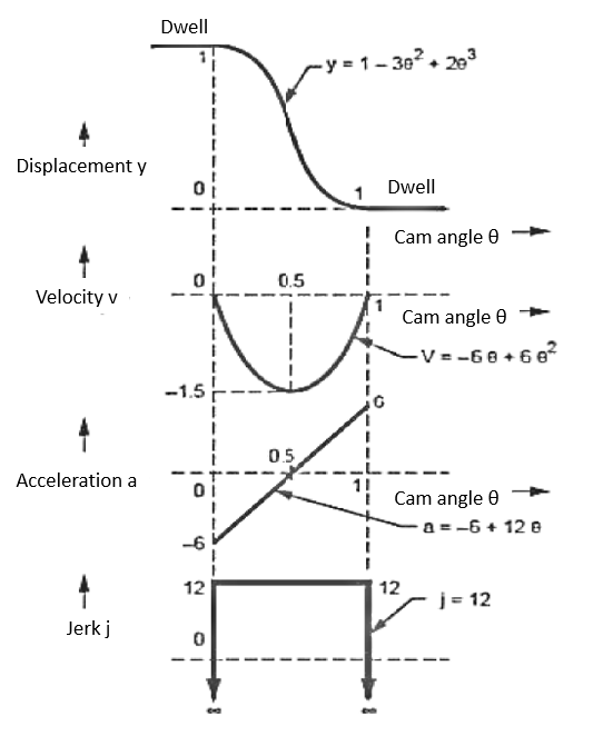
  • Figure shows the plot of displacement , velocity , acceleration and jerk  curves.
  • From Fig  it is clear that, acceleration is finite at all points for the complete stroke and jerk is constant throughout the stroke. But it is infinite at the start and end of each stroke which causes high inertia forces at these points.
  • The 3-4-5 Polynomial D-R-D Cam

     In this type of cam curves, six boundary conditions are used hence displacement equation is given by,

    ……. 1

    Boundary conditions are


    Differentiating the above equation w.r.t to get velocity follower,

    Again differentiating w.r.t. to get acceleration of follower,

    Initially put boundary conditions in equation (1)

    ……..(4)

    Now put boundary condition in equation (2)

    And                                                  

    Now put boundary conditions in equation (3)

    And                                   

    Put   in equation (4) and (5)

    Solving equation (6),(7) and (8) we get

    Substituting all these values in equation (1)

    Velocity                  

    Acceleration   

    Jerk                          

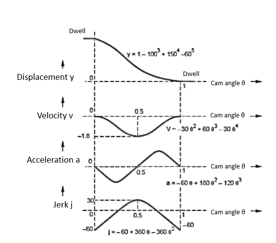
  • Fig shows the plot of displacement , velocity , acceleration and jerk curves
  • From fig it is clear that the value of acceleration and jerk is finite for the complete stroke including start and end.
  • Hence, these types of curves are commonly used for high speed applications. These curves are similar to cycloidal curves.
  • Numerical:

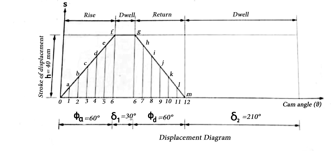
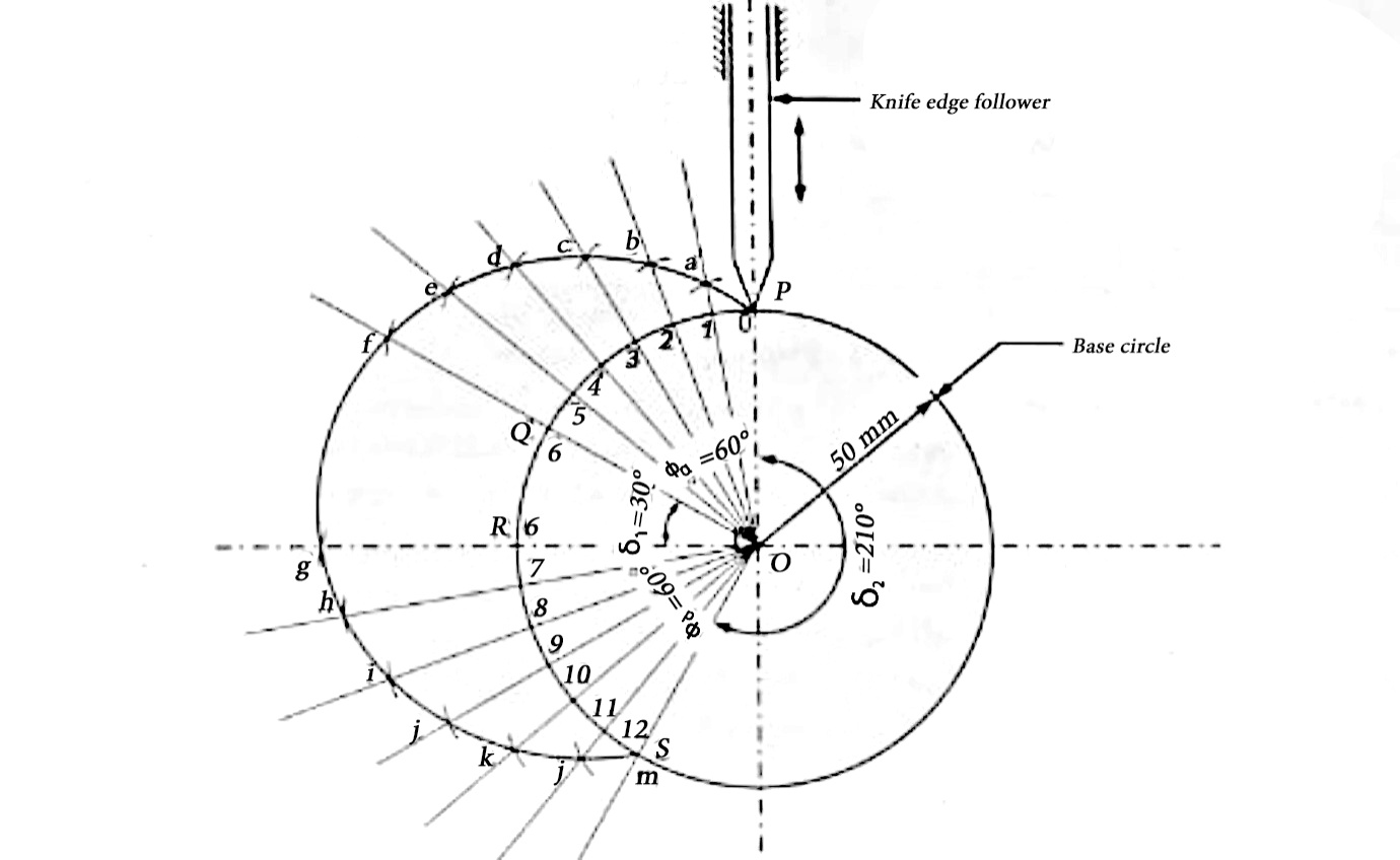
    1. Cam is to give the following motion to a knife edge follower

  • Out stroke during 60 degree of CAM rotation
  • Dwell for the next 30 degree of CAM rotation
  • Return stroke during next 60 degree of CAM rotation
  • Dwell for the remaining 210 degree of CAM rotation.
  • The stroke of the follower is 40 mm and the minimum radius of the cam is 50mm. The follower moves the uniform velocity during both the out stroke and return stroke. Draw the profile of the cam, when the follower process through the axis of the camshaft.

    Solution

    Outstroke

    Dwell

    Return stroke

    Remaining cam angle

    Stroke in mm

    Cam radius in mm


    600

    300

    600

    2100

    40

    50

    Procedure

    Displacement diagram

  • Draw the displacement diagram as per the procedure explained in section 4.2.1 for the given conditions
  • Procedure to draw cam profile

  • Draw base circle having radius equal to minimum radius (50mm) of cam. Mark the centre of the drawn as O.
  • As the axis of follower passes through the axis of camshaft, Mark the trace point as P on base.
  • Assume the cam rotation to be clockwise. Therefore, in anticlockwise direction from line PQ and
      (600)from QO mark
    (300) and from RO
    (600). Remaining cam angle represents dwell period.
  • Divide outstroke angle into 6 equal parts and mark points 0, 1, 2, 3, 4, 5 and 6. Similarly divide return stroke into 6 equal parts and mark points 6, 7, 8, 9, 10 11 and 12.
  • Joining the points 0, 1, 2, 3, 4, 5 and 6 and points 6, 7, 8, 9, 10, 11 and 12 to the centre point and extend the obtained lines beyond base circle.
  • On the above extended line, mark off the distances 1-a,2-b,3-c,4-d ,5-e,6-f,6-g,7-h,8-I,9-j,10-k,11-l and 12-m, measured from displacement diagram.
  • Obtain a smooth curve starting from point P and passing through points a, b, c, d, e, f, g,h, i, j, l, m and again to point P to get the required cam profile.
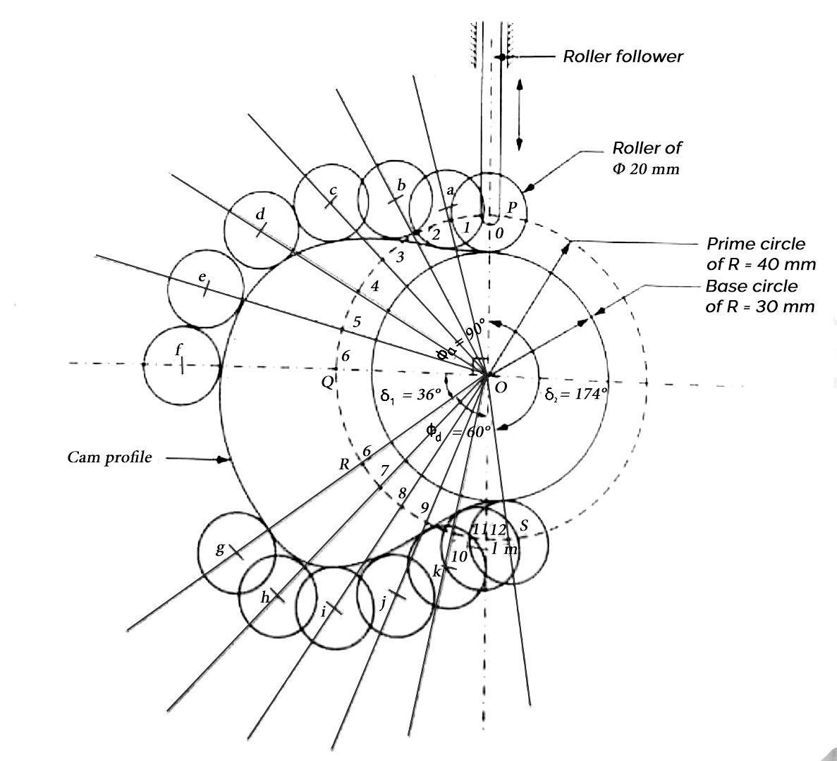
  •  2. Draw the profile of a cam to raise a valve with SHM through 40 mm in 1/4th of revolution keep it fully raised through 1/10th of revolution and to lower it with uniform acceleration and retardation in 1/6th of revolution. The valve remains closed during rest of the revolution. The diameter of roller is 20mm and minimum radius of CAM to be 30mm. Axis of the valve road passes through the axis of cam shaft.

    Solution:

    Outstroke =1/4th of revolution=1/4 ×360=900

    Dwell=1/10th of revolution=1/10×360=360

    Return stroke=1/6th of revolution=1/6×360=600

    Outstroke

    Dwell

    Return stroke

    Remaining cam angle

    Stroke in mm

    Cam radius in mm

    Diameter of roller in mm

    Radius of roller in mm

    Prime circle radius in mm

    90°

    36°

    60°

    174°

    40

    30

    20

    10

    40


    Prime circle radius is calculated by adding the radius of roller to the radius of base circle/cam radius

    Procedure:

    Displacement diagram
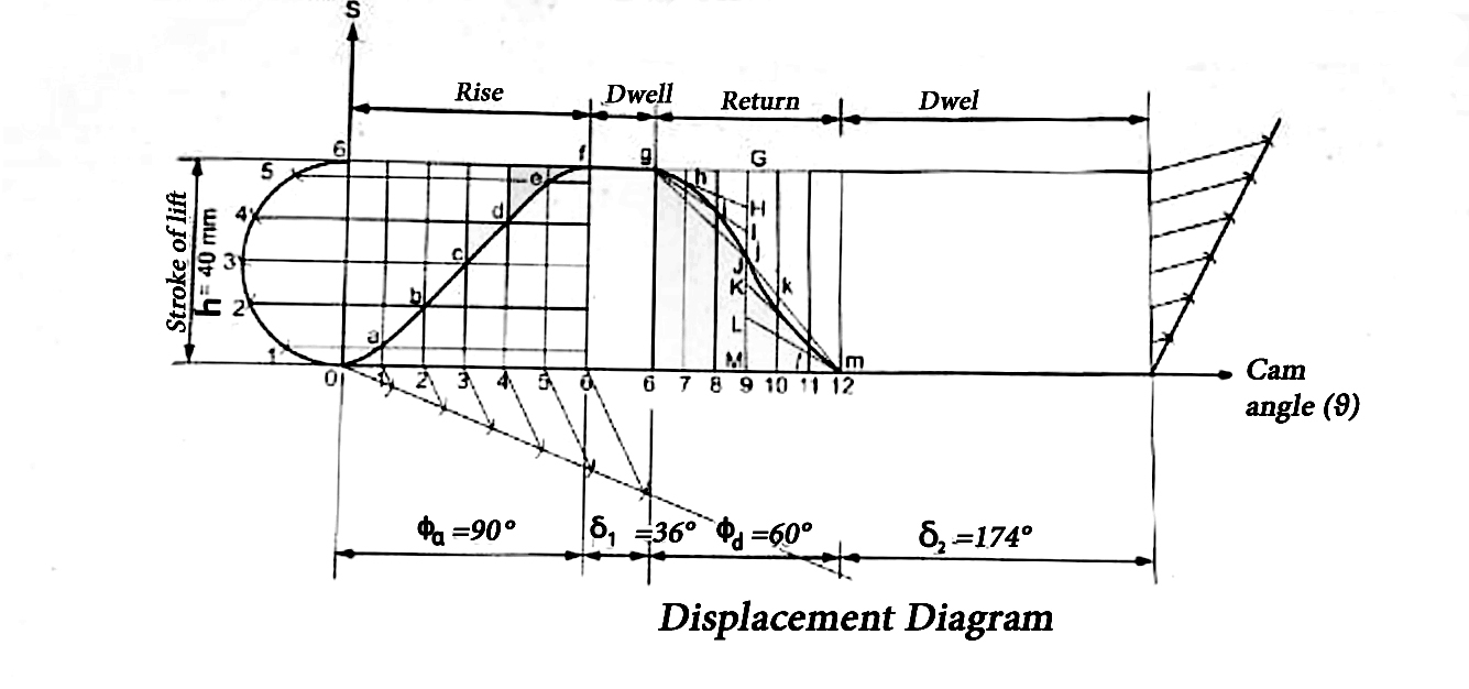
  • Draw the displacement diagram as per the procedure explained in section 4.2.2 and 4.2.3 for the given conditions
  • Procedure to draw cam profile:

  • Draw a circle having radius equal to minimum radius of cam (30mm) . Mark the centre at O. Similarly, draw prime circle of radius 40mm.
  • As the axis of follower passes through the axis of camshaft, Mark the trace point as P on the circle.
  • Assume the cam rotation to be clockwise. Therefore, in anticlockwise direction from PQ  mark
    (90°), from QO, mark
    (36°) and from RO
    (60°). Remaining cam angle represents dwell period.
  • Divide outstroke angle into 6 equal parts and mark points 0, 1, 2, 3, 4, 5 and 6. similarly, divide return stroke into 6 equal parts and Mark point 6, 7, 8, 9, 10, 11 and 12 on the circle.
  • Joining the points 0, 1, 2, 3, 4, 5 and 6 and. 6, 7, 8, 9, 10, 11 and 12 to the centre point and extend the obtained lines beyond prime circle.
  • On the above extended line, mark off the distances 1-a,2-b,3-c,4-d ,5-e,6-f,6-g,7-h,8-I,9-j,10-k,11-l and 12-m, measured from displacement diagram.
  • Draw rollers of radius 10mm with the centres as a, b, c, d, e, f, g, h, i,j,k,l and m.
  • Draw a smooth curve which is tangential to all the above rollers to get the required cam profile.
  •  3. A flat faced mushroom follower is operated by a uniformly rotating cam. The follower is raised through a distance of 25mm in 120° rotation of the cam, remains at rest for the next 30 degree and is lowered during further 120-degree rotation of the cam. The raising of the following takes place with cycloidal motion and the lowering with uniform acceleration and deceleration. However, the uniform acceleration is 2/3 of the uniform deceleration. The least radius of the cam is 25mm which rotates at 300rpm. Draw the cam profile and determine the values of the maximum velocity and maximum acceleration during rising, and maximum velocity and uniform acceleration and deceleration during lowering of the follower.

    Solution:

    h=25mm 

    During the return stroke, as the uniform acceleration is 2/3 of the uniform deceleration, the uniform deceleration is 3/2 of the uniform acceleration.

    Let the uniform acceleration be f so that the uniform deceleration be (3/2)f.

    Time of acceleration

    Final velocity,

    v=u +ft=ft ……. Initial velocity = 0

    Or

     Time of deceleration

    Initial velocity is v and final velocity zero.

    Therefore

    0=v - (3/2) f t'

    Where t’ is the time of deceleration and negative sign due to declaration.

    The time of deceleration is 2/3 of the time of acceleration.

    Displacement

    During acceleration

    During deceleration=

    [As initial velocity f t and time taken 2/3t]

    Comparison of i  and ii shows that the distance travelled during deceleration period is 2/3 of the distance travel during acceleration.

    The displacement diagram has been shown in figure a. During the return stroke, the time of acceleration and the displacement are 3/2 times of the corresponding values during the deceleration. Thus, the time of acceleration is 3/5 of the total time of return and the displacement is 3/5 of the total displacement.

    To draw the cam profile, proceed as follows:

  • Draw circle with radius 
  • Take angles 
    in the anti-clockwise direction if the cam rotation is assumed clockwise.
  • Divide 
       into same number of parts as in displacement diagram.
  • Draw radial lines and on them mark the distances 1-1’,2-2’,3-3’ etc.
  • Draw the follower in all the positions by drawing perpendicular to the radial lines at 1’,2’,3’ etc. in all the positions the axis of the follower passes through the centre O.
  • Draws a curve to the flat faces of the following representing the cam profile.
  • During ascent

    During descent

    v=f t         

    v  will  the maximum at the end of acceleration period.

    At the end of the acceleration period,

    And the time taken to travel this distance is found as under,

    Time for 300rev.=60s

    Time for 1 rev =60/300 =0.2sec.

    Time for

     Uniform acceleration

    Uniform deceleration

    =18.75×3/2 =28.13


    4. The following data related to a cam operating and oscillating roller follower:

    Minimum radius of cam=44mm

    Diameter of roller=14mm

    Length of the follower arm=40mm

    Distance of fulcrum centre from cam  centre=50mm

    Angle of ascent=75°

    Angle of decent=105°

    Angle of Dwell for follower in the highest position=60°

    Angle of oscillation of follower=28°

    Draw the profile of the cam if the ascent and decent both take place with SHM.

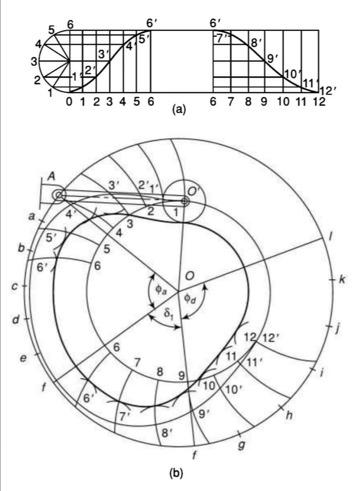
    Solution:

    Follower arm length =40mm

    The displacement diagram has been shown in figure a .

    To draw the cam profile, proceed as follows:

  • Draw circle with radius
  • Assuming the initial position of the roller centre vertically above the cam centre O, locate the fulcrums centres as its distances from the cam centre and the roller centre arc known.
  • Draw a circle with radius OA and centre at O.
  • On the circle through A, starting from OA, take angles
        
  • Divide the angles 
      into same number of parts as is done in the displacement diagram and obtain the points a, b ,c ,d etc. On the circle through A.
  • With the centres   A,a,b etc. X with radii equal to length of the arm.
  • Mark distances 1-1’,2-2’,3-3’,etc.,on these arcs as shown in diagram. It is on the assumption that for small angular displacement, the linear displacements on the arcs and on the straight line are the same.
  • With 1’,2’,3’ etc. Draw series of arcs of radii equal to
  • Draw smooth curve tangential to all the arcs and obtain the required cam profile.
  •  

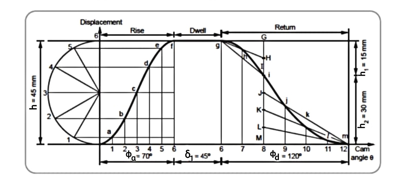
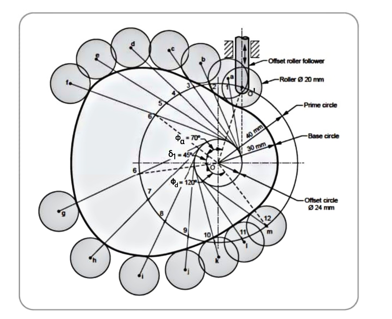
    5.     The following data is related to a cam profile, in which the follower moves with SHM during the lift and returning it with acceleration and deceleration , acceleration being half the deceleration.

    Minimum radius of cam=30mm

    Roller radius =10mm

    Lift of follower =45mm

    Offset of follower axis=12mm

    Angle of ascent =700

    Angle of descent=1200

    Angle of dwell between ascent and descent=450

    Speed of cam=300rpm

    Draw the cam profile and determine maximum velocity, maximum acceleration during lift.

    Solution Given data

    N=300rpm   

    It is given that, during return stroke nature of follower motion is uniform acceleration and retardation but acceleration period is half of the deceleration period,

    Let be the angle of acceleration and retardation respectively,

    Similarly, be the displacement of follower during acceleration and retardation period.

    The displacement diagram has been shown in figure a.

    To draw the cam profile, proceed as follows:

  • Draw circle with radius
  • Draw another circle with radius e = 12 mm.
  • Join O-O’. Divide the circle into four parts with angles
    &
    Starting from O-O’.
  • Divide the angles 
      into same number of parts as is done in the displacement diagram & obtain points 1, 2, 3 etc on the circumference of circle with
  • Draw tangents to the circle with radius e from points 1, 2 , 3 etc.
  • On the extension of the tangent lines, mark the distance from the displacement diagram.
  • Draw a smooth curve through 0’, 1’, 2’ etc.
  •  

      Maximum velocity of follower during lift is

    Maximum acceleration of follower during lift is


    6.     An eccentric cam of eccentricity 3.75cm drives a follower of mass 1.75Kg. The spring holding the follower against the cam has stiffness of 24 N/mm and has initial compression of 3.125 cm. It is observed that jump occurs at cam rotation 1000 from the lowest position of the cam. Find out the speed of cam. Find out the speed of cam in r.p.m. Also find out maximum usable speed of cam without jump.

    Solution Given that :

    e =3.75cm =0.0375m     m=1.75Kg   K=24N/mm   =24*N/m

    To find i) Cam speed (N)  ii)  Limiting speed

    Step-I     Calculate the speed of cam

    Preload in the spring is,

    P=767.1675N

    Contact force between cam and follower is

    But jump will occur when F=0

    N=3819.8704 rpm

     This is the speed at which jump will occur.

    To avoid cam jump limiting speed is,

    Now                        

    It means to avoid cam jump; the cam speed should be less than or equal to limiting speed i.e.

    Reference:

    1. Ghosh Malik, Theory of Mechanism and Machines, East-West Pvt. Ltd.

    2. Hannah and Stephans, Mechanics of Machines, Edward Arnolde Publication.

    3. R L Norton, Kinematics and Dynamics of Machinery, First Edition, McGraw Hill Education

    (India) P Ltd. New Delhi

    4. Sadhu Singh, Theory of Machines, Pearson

    5. D.K. Pal, S.K. Basu, Design of Machine Tools, Oxford & Ibh Publishing Co Pvt. Ltd.

    6. Dr. V. P. Singh, Theory of Machine, Dhanpatrai and sons.

    7. C. S. Sharma & Kamlesh Purohit, “Theory of Machine and Mechanism”, PHI.


    Index
    Notes
    Highlighted
    Underlined
    :
    Browse by Topics
    :
    Notes
    Highlighted
    Underlined