Unit – 5
Synthesis of Mechanism
Kinematics synthesis
Synthesis process may be accomplished, in general, in three interrelated faces:
1. Type synthesis
2. Number synthesis
3. Dimensional synthesis
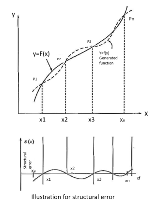
1. Path generation
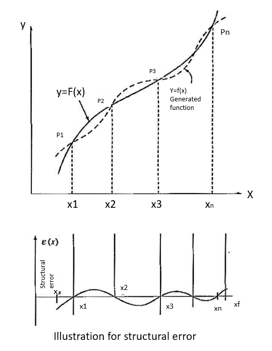
2. Function generation
3. Motion generation


Where  are the accuracy points. Thus, for first, second, and third accuracy points, j is equal to 1,2, and 3 respectively.
n = total number of accuracy points.


Here. 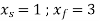
And n= number of accuracy points=3
First, second and third accuracy points are
And 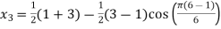

Corresponding values of the dependent variable by, as obtained by substituting  values (j=1,2,3) in the function


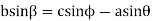
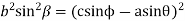
Squaring both sides


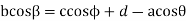
Now taking the sum of the components along y-axis we have

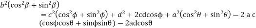
Squaring both sides

Adding equations (ii) and (iv)


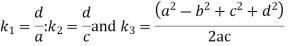
Let 
Equation (v) can be written as


The equation (vii) is known as the Freudenstein equation.


Where 


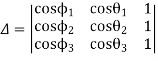
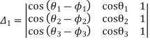
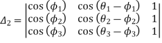
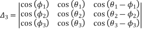
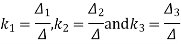
Now the values of  are given by

Numericals
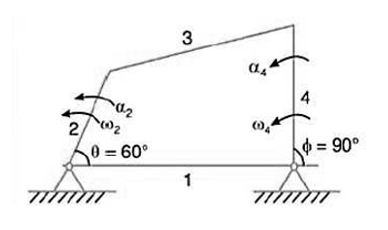
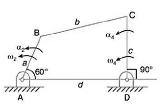
1. Synthesize a four-bar linkage as shown in Fig using Freudenstein’s equation to satisfy in one of its positions. The specification of position  velocity
  and accelerations
  are as follows:


Given 

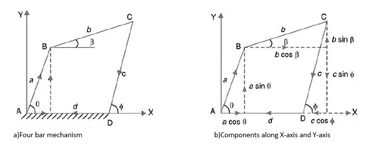
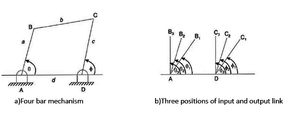
The four-bar linkage is shown in Figure Let
AB = Input Link=a
BC=Coupler=b
CD=Output link =c and
AD=Fixed link =d
The Freudenstein’s equation is given by

Substituting the value of  in equation (i)


Differentiating equation (i) with respect to time


Now differentiating equation(iii) with respect to time

= - 


=-[sin(60-90)(2-7)+(5-2)2 cos(60-90)]

From equation (iv) and (v)

From equation (v)

And from equation (ii)

Assuming the length of one of the links say an as one unit we get the length of the links as follows
We know that
 units
units
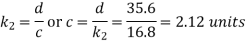
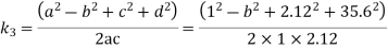
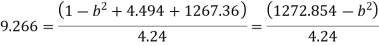

b=35.12 units
2. Synthesize a four-bar mechanism to generate a function y = sinx for  . The range of the output crank may be chosen as 60 while that of input crank be 1200. Assume three precision points which are to be obtained from Chebyshev spacing. Assume fixed link to be 52.5mm long and
Solution Given 
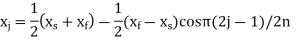
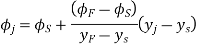
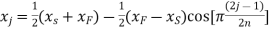
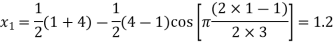
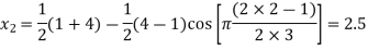
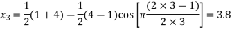
The three values of x corresponding to three precision points according to Chebyshev spacing are given by
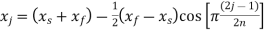 where j=1,2,3

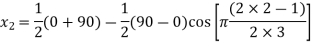
=

=
Since y = sinx, therefore corresponding values of y are
Also 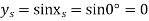
And 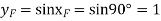
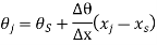
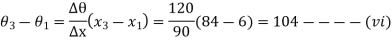
The relation between the input angle  and x is given by
 where j=1,2,3
The above expression may be written as
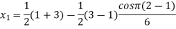
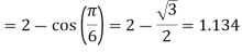
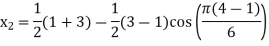
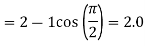
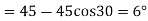
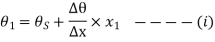
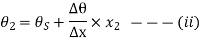
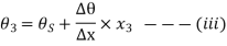
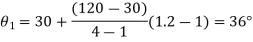
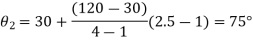
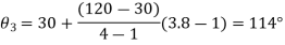
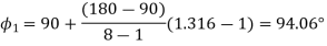
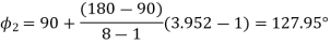
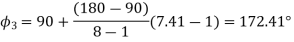
The three values of  corresponding to three precision points are given by
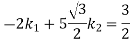
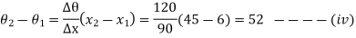
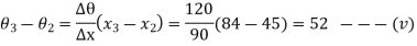
From equations (i) (ii) and (iii)
Since 


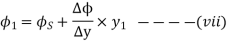
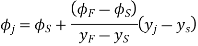
The relation between the output angle and y is given by
The expression may be written as
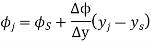
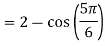
The three values of  corresponding to three precision points are given by
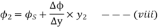
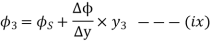
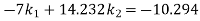
From equations (vii),(viii) and (ix)


Since  therefore


We have calculated above the three positions.
Let a=Length of the input crank
b=Length of the coupler
c=Length of the output crank, and
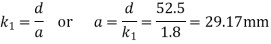
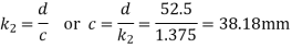
d= Length of the fixed crank=52.5mm
We know that Freudenstein displacement equation is

Where 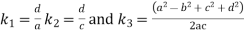
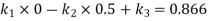
The equation (xiii) for the first position of input and output crank may be written as


Similarly, for the second position


And for the third position (when 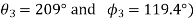


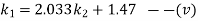
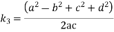
Solving the three simultaneous equations (xiv), (xv) and (xvi) we get

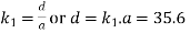
Since the length of the fixed link (i.e. d=52.5mm) is known therefore we get the length of other links as follows:
We know that
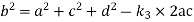

b=75.88mm
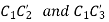
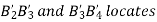
3. Design a slider-crank mechanism to co-ordinate three positions of the input link and the slider for the following angular and linear displacement of the input link and the slider respectively,


Solution The required slider-crank mechanism can be designed as follows:


Then, ABC is the required slider-crank mechanism. The figure shows the same in three positions.
(a)
(b)
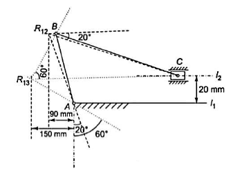
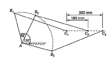
4. Design a slider-crank mechanism to co-ordinate three positions of the input and the slider for the following data by inversion method
Eccentricity = 20 mm.
For the given to angular displacement of the input link and the two linear displacements of the slider along with the eccentricity e, the required slider-crank mechanism is obtained as follows:


Then  is the required slider-crank mechanism. Figure b shows the mechanism in the required three positions.
(a)
(b)
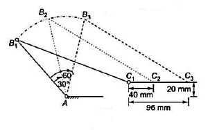
5. Design of four-link mechanism to co-ordinate four positions of the input and output links for the following angular displacement of the input link and the output link respectively:


Solution. Make the following construction:


(a)
(b)
6. A four-bar mechanism is to be designed by using three precision points to generate the function
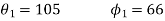
Assuming  starting position and
  finishing position for the input link and
  starting position and
  finishing position for the output link, find the values of x, y,
  corresponding to the three precision points.
Given 
Values of x
The three values of x corresponding to three precision points according to Chebyshev’s spacing are given by:
 where j=1,2 and 3
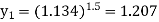
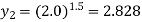
Values of y
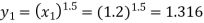
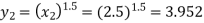
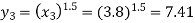
Since  therefore the corresponding values of y are
Values of 
The three values of  corresponding to three precision points are given by
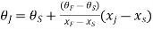 , where j=1,2,3
Value of 
The three values of  corresponding to three precision points are given by
Reference:
1. Ghosh Malik, Theory of Mechanism and Machines, East-West Pvt. Ltd.
2. Hannah and Stephans, Mechanics of Machines, Edward Arnolde Publication.
3. R L Norton, Kinematics and Dynamics of Machinery, First Edition, McGraw Hill Education
(India) P Ltd. New Delhi
4. Sadhu Singh, Theory of Machines, Pearson
5. D.K. Pal, S.K. Basu, Design of Machine Tools, Oxford & Ibh Publishing Co Pvt. Ltd.
6. Dr. V. P. Singh, Theory of Machine, Dhanpatrai, and sons.
7. C. S. Sharma & Kamlesh Purohit, “Theory of Machine and Mechanism”, PHI.


