UNIT 2
GAS LAW AND GAS PROCESSES
a. Ideal gas:
Gases are complicated. They're full of billions and billions of energetic gas molecules that can collide and possibly interact with each other. Since it's hard to exactly describe a real gas, people created the concept of an Ideal gas as an approximation that helps us the model and predict the behaviour of real gases. The term ideal gas refers to a hypothetical gas composed of molecules that follow a few rules:
Ideal gas molecules do not attract or repel each other. The only interaction between ideal gas molecules would be an elastic collision upon impact with each other or an elastic collision with the walls of the container.
Ideal gas molecules themselves take up no volume. The gas takes up the volume since the molecules expand into a large region of space, but the Ideal gas molecules are approximated as point particles that have no volume in and of themselves.
There are no exactly ideal gases, but there are plenty of gases that are close enough that the concept of an ideal gas is an extremely useful approximation for many situations. In fact, for temperatures near room temperature and pressures near atmospheric pressure, many of the gases we care about are very nearly ideal.
An ideal gas can be characterized by three state variables: absolute pressure (P), volume (V), and absolute temperature (T). The relationship between them may be deduced from kinetic theory and is called the
Ideal gas law: PV = nRT = NkT
- n = number of moles
- R = universal gas constant = 8.3145 J/mol K
- N = number of molecules
- k = Boltzmann constant = 1.38066 x 10⁻²³ J/K = 8.617385 x 10⁻⁵ eV/K
- k = R/NA
- NA = Avogadro's number = 6.0221 x 10²³ /mol
b.) Boyle’s law:
Boyle’s law is a gas law that states that the pressure exerted by a gas (of a given mass, kept at a constant temperature) is inversely proportional to the volume occupied by it. In other words, the pressure and volume of a gas are inversely proportional to each other as long as the temperature and the quantity of gas are kept constant. Boyle’s law was put forward by the Anglo-Irish chemist Robert Boyle in the year 1662.
For a gas, the relationship between volume and pressure (at constant mass and temperature) can be expressed mathematically as follows.
P ∝ (1/V)
Where P is the pressure exerted by the gas and V is the volume occupied by it. This proportionality can be converted into an equation by adding a constant, k.
P = k*(1/V) ⇒ PV = k
The pressure v/s volume curve for a fixed amount of gas kept at constant temperature is illustrated below.
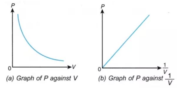
It can be observed that a straight line is obtained when the pressure exerted by the gas (P) is taken on the Y-axis and the inverse of the volume occupied by the gas (1/V) is taken on the X-axis.
Formula and Derivation
As per Boyle’s law, any change in the volume occupied by a gas (at constant quantity and temperature) will result in a change in the pressure exerted by it. In other words, the product of the initial pressure and the initial volume of a gas is equal to the product of its final pressure and final volume (at constant temperature and number of moles). This law can be expressed mathematically as follows:
P1V1 = P2V2
Where,
- P1 is the initial pressure exerted by the gas
- V1 is the initial volume occupied by the gas
- P2 is the final pressure exerted by the gas
- V2 is the final volume occupied by the gas
This expression can be obtained from the pressure-volume relationship suggested by Boyle’s law. For a fixed amount of gas kept at a constant temperature, PV = k. Therefore,
P1V1 = k (initial pressure * initial volume)
P2V2 = k (final pressure * final volume)
∴ P1V1 = P2V2
This equation can be used to predict the increase in the pressure exerted by a gas on the walls of its container when the volume of its container is decreased (and its quantity and absolute temperature remain unchanged)
Numerical on Boyle’s law:
Question) A fixed amount of a gas occupies a volume of 2L and exerts a pressure of 500 kPa on the walls of its container. What would be the pressure exerted by the gas if it is completely transferred into a new container having a volume of 4 liters (assuming the temperature and quantity of gas remains constant)?
Solution)
Given,
Initial volume (V1) = 2L
Initial pressure (P1) = 500 kPa
Final volume (V2) = 4L
As per Boyle’s law, P1V1 = P2V2 ⇒ P2 = (P1V1)/V2
P2 = (2L * 500 kPa)/4L = 250 kPa
Therefore, the gas exerts a pressure of 250 kPa on the walls of the 4-liter container.
c) Charles law
Charles’ law is one of the gas laws which explain the relationship between volume and temperature of a gas. It states that when pressure is held constant, the volume of a fixed amount of dry gas is directly proportional to its absolute temperature. When two measurements are in direct proportion then any change made in one of them affects the other through direct variation. Charles’ Law is expressed by the equation:
VαT
Or
V1 / T1=V2 / T2
Where,
V1 and V2 are the Initial Volumes and Final Volume respectively. T1 refers to the Initial Temperature and T2 refers to the Final Temperature. Both the temperatures are in the units of Kelvin.
Jacques Charles, a French scientist, in 1787, discovered that keeping the pressure constant, the volume of a gas varies on changing its temperature. Later, Joseph Gay-Lussac, in 1802, modified and generalized the concept as Charles’s law. At very high temperatures and low pressures, gases obey Charles’ law.
Derivation:
Charles’ Law states that at constant pressure, the volume of a fixed mass of a dry gas is directly proportional to its absolute temperature. We can represent this using the following equation:
VαT
Since V and T vary directly, we can equate them by making use of a constant k.
V / T=constant=k
Let V1 and T1 be the initial volume and temperature of an ideal gas. We can write an equation I as:
V1 / T1= k ———– (I)
Let’s change the temperature of the gas to T2. Consequently, its volume changes to V2. So we can write,
V2 / T2=k ———– (II)
Equating equations (II) and (III),
V1 / T1=V2 / T2=k
Hence, we can generalize the formula and write it as:
(V1) / (T1)=(V2) / (T2)
Or
V1T2=V2T1
On heating a fixed mass of gas, that is, increasing the temperature, the volume also increases. Similarly, on cooling, the volume of the gas decreases.
Charles’ Law in Real Life:
Charles’ law has a wide range of applications in our daily life. Some of the common examples are given below:
- In cold weather or environment, balls and helium balloons shrink.
- In bright sunlight, the inner tubes swell up.
- In colder weather, the human lung capacity will also decrease. This makes it more difficult to do jogging or athletes to perform on a freezing winter day.
Numerical Question on Charles law:
Q) Find the initial volume of a gas at 200 K, if the final volume is 8 L at 100 K
A) Solution: Given, V1=?
V2 =8 L
T1= 200 K
T2= 100 K
Using Charles Law, V1 / T1= V2 / T2
V1 / 200 = 8 / 100
V1=8 * 200 / 100
V1=16L (The initial volume of a gas at 200 K is 16 liters.)
d) Characteristic gas equation
Characteristic Equation of a Gas is a modified form of the general gas equation. If the volume (v) in the general gas equation is taken as that of 1 kg of gas (known as its specific volume, and denoted by Vs), then the constant C (in the general gas equation) is represented by another constant R (in the characteristic equation of gas).
Thus, the general gas equation may be rewritten as
P*vs= RT
where R is known as characteristic gas constant or simply gas constant.
For any mass m kg of gas, the characteristic gas equation becomes:
m*p*vs = m*R*T
We know that ,
Specific volume= Volume / mass
So, put in above
Mass (m) *specific volume (vs) = Volume (v)
P*v = m*R*T
1. In S.I. Units, the pressure is expressed in the bar (1 bar = 100 kN / m2).
2. The unit of gas constant (R), in S.I. Units, is N-m / kg K or J / kg K (1 Nm = 1J)
3. The value of gas constant (R) is different for different gases. Its value for atmospheric air is taken 287 / kg K or 0.287 kJ / kg K.
4. The equation P*v = m*R*T may also be expressed in another form i.e.,
p= (m/v)*R*T
P = ρ*R*T
Where ρ (rho) is the density of the given gas.
e) Universal gas constant
When the molecular mass of any gas is multiplied by its specific gas constant (R), it is observed that the product R is always the same for all gases. This product is called universal gas constant and it is denoted as R.
From the SI system, the value of the universal gas constant is 8.314 kJ/mole.K
Let us consider the pressure exerted by the gas to be p
The volume of the gas be v
Temperature be T
n be the number of moles of gas
Universal gas constant R
According to Boyle’s Law,
At constant n & T, the volume bears an inverse relation with the pressure exerted by a gas.
v ∝ 1/ p ………………………………(i)
According to Charles’ Law,
When p & n are constant, the volume of a gas bears direct relation with the Temperature.
v ∝ T …………………………(ii)
According to Avogadro’s Law,
When p & T are constant, then the volume of a gas bears direct relation with the number of moles of gas.
v ∝ n …………………………(iii)
Combining all the three equations, we have-
v ∝ n T / p
p.v=nRT
Where R is the Universal gas constant, which has a value of 8.314 J/mol-K
f) Avogadro law
Avogadro’s law, also known as Avogadro’s principle or Avogadro’s hypothesis, is a gas law that states that the total number of atoms/molecules of a gas (i.e. the amount of gaseous substance) is directly proportional to the volume occupied by the gas at constant temperature and pressure. Avogadro’s law is closely related to the ideal gas equation since it links temperature, pressure, volume, and amount of substance for a given gas.
Avogadro’s law is named after the Italian scientist Amedeo Carlo Avogadro, who suggested that two dissimilar ideal gases occupying the same volume at a given (constant) temperature and pressure must contain an equal number of molecules.
Formula and Graphical Representation
At constant pressure and temperature, Avogadro’s law can be expressed via the following formula:
V ∝ n
V/n = k
Where V is the volume of the gas, n denotes the amount of gaseous substance (often expressed in moles), and k is a constant. When the amount of gaseous substance is increased, the corresponding increase in the volume occupied by the gas can be calculated with the help of the following formula:
V1/n1 = V2/n2 (= k, as per Avogadro’s law).
The graphical representation of Avogadro’s law (with the amount of substance on the X-axis and volume on the Y-axis) is illustrated below.
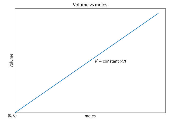
Here, the straight line (which indicates that the two quantities are directly proportional) passes through the origin, implying that zero moles of gas will occupy zero volume.
Derivation
Avogadro’s law can be derived from the ideal gas equation, which can be expressed as follows:
PV = nRT
Where,
- ‘P’ is the pressure exerted by the gas on the walls of its container
- ‘V’ is the volume occupied by the gas
- ‘n’ is the amount of gaseous substance (number of moles of gas)
- ‘R’ is the universal gas constant
- ‘T’ is the absolute temperature of the gas
Rearranging the ideal gas equation, the following equation can be obtained.
V/n = (RT)/P
Here, the value of (RT)/P is a constant (since the temperature and pressure kept constant and the product/quotient of two or more constants is always a constant). Therefore:
V/n = k
Thus, the proportionality between the volume occupied by a gas and the number of gaseous molecules is verified.
Molar Volume of a Gas
As per Avogadro’s law, the ratio of volume and amount of gaseous substance is constant (at constant pressure and temperature). The value of this constant (k) can be determined with the help of the following equation:
k = (RT)/P
Under standard conditions for temperature and pressure, the value of T corresponds to 273.15 Kelvin and the value of P corresponds to 101.325 kilos Pascal’s. Therefore, the volume occupied by one mole of a gas at STP is:
Volume occupied by 1 mole of gas = (8.314 J.mol-1.K-1)*(273.15 K)/ (101.325 kPa) = 22.4 litres
Therefore, one mole of any gaseous substance occupies 22.4 liters of volume at STP.
Numerical on Avogadro numbers:
Question- Two moles of helium gas fill up an empty balloon to a volume of 3 liters. What would be the volume of the balloon if an additional 4 moles of helium gas is added? (Assume that the temperature and the pressure are kept constant)
Answer- Given,
The initial amount of helium (n1) = 2 mol
The initial volume of the balloon (V1) = 3 L
The final amount of helium (n2) = 2 mol + 4 mol = 6 mol
As per Avogadro’s law, V1/n1 = V2/n2
Therefore, the final volume of the balloon (V2) = (V1n2)/n1
= (3 L*6mol)/2mol
= 9 L
The balloon would occupy a volume of 9 liters when it contains 6 moles of helium gas.
Sometimes our bodies starts to sweat and feel warm when we are in a room full of people and the sweating becomes excessive if the room size is small. This happens because our body is trying to cool off hence heat transfers from our body in the form of ‘sweat’. This entails the first law of thermodynamics.
The first law of thermodynamics states that the total energy of an isolated system is constant. Energy can be transformed from one form to another, but can neither be created nor destroyed.
According to this law, some of the heat given to the system is used to change the internal energy while the rest is doing work by the system. Mathematically,
ΔQ=ΔU+ΔW
Where,
ΔQ = Heat supplied to the system
ΔW= Work done by the system.
ΔU = Change in the internal energy of the system.
If Q is positive, then there is a net heat transfer into the system, if W is positive, then there is work done by the system. So positive Q adds energy to the system and positive W takes energy from the system. It can also be represented as ΔU=ΔQ−W
We can say that internal energy tends to increase when the heat is given to the system and vice versa.
a) First law applied to constant volume (Isochoric process)
Suppose a gas enclosed in a rigid vessel is interacting with the surroundings and absorbs energy Q as heat. Since the vessel is rigid, the work done W due to expansion or compression is zero. Applying the first law, we get
DU = dQ or Q = U2 –U1
That is, heat interaction is equal to the change in the internal energy of the gas. If the system contains a mass m equal to an ideal gas, then
Q = ΔU = mCv (T2 –T1)
The path followed by the gas is shown on a P-V diagram. Now consider the fluid contained in a rigid vessel as shown. The vessel is rigid and insulated. Shaft work is done on the system by a paddle wheel as shown in Fig. a. In Fig. b electric work is done on the system. Since the vessel is rigid, the PdV work is zero. Moreover, the vessel is insulated, and hence dQ = 0. Application of the first law of thermodynamics gives
DU = dQ – dW = dQ – (dWpdv + dWs)
Or dU = -dWs or – Ws = ΔU = U2 –U1
Where dWpdv is the compression /expansion work and dWs is the shaft work. That is an increase in internal energy of a system at a constant volume, which is enclosed by an adiabatic wall, is equal to the shaft work done on the system.
b) Constant pressure (Isobaric process):
Several industrial processes are carried out at constant pressure. A few examples of constant pressure processes are: (a) reversible heating/cooling of a gas (b) phase change (c) paddlewheel work (d) electrical work. For a constant pressure process, the work done W is given by
W = ∫PdV = P (V2-V1)
Application of the first law of thermodynamics gives
DU = dQ – dW
= dQ – PdV
= dQ – d (PV)
Or dQ = dU + d (PV) = d(U + PV) = dH
Or Q = ΔH
That is in a constant pressure process, the heat interaction is equal to the increase in the enthalpy of the system. Now consider the constant pressure processes in which the system is enclosed by an adiabatic boundary. Application of the first law gives:
DU = dQ – dW = dQ – (PdV + dWs)
Here, the network done (dW) consists of two parts – the PdV work associated with the motion of the boundary and (-dWs), the shaft work (or electrical work) done by the surroundings. Since the system is enclosed by an adiabatic boundary, dQ = 0 the equation can be written as
-dWs = dU + d (PV) = dH
That is, the increase in the enthalpy of the system is equal to the shaft work done on the system.
c) Constant temperature
Suppose a gas enclosed in the piston-cylinder assembly is allowed to expand from P1 to P2 while the temperature is held constant. Then an application of the first law gives:
DU = dQ – dW = dQ –PdV
It is not possible to calculate work and heat interactions unless the relationships between the thermodynamic properties of the gas are known. Suppose the gas under consideration is an ideal gas (which follows the relation Pv = RT and u =
u (T) only) then for an isothermal process,
DU = 0
DQ = PdV = R.T.dv /v or Q =W = RTln(v2/v1)
d) Reversible adiabatic process:
The reversible adiabatic process is also called an Isentropic Process. It is an idealized thermodynamic process that is adiabatic and in which the work transfers of the system are frictionless; there is no transfer of heat or matter and the process is reversible. Such an idealized process is useful in engineering as a model of and basis of comparison for real processes.
Adiabatic process derivation
The adiabatic process can be derived from the first law of thermodynamics relating to the change in internal energy dU to the work dW done by the system and the heat dQ added to it.
DU =dQ-dW
DQ =0 by definition
Therefore, 0=dQ=dU +dW
The word done dW for the change in volume V by dV is given as PdV.
The first term is specific heat which is defined as the heat added per unit temperature change per mole of a substance. The heat that is added increases the internal energy U such that it justifies the definition of specific heat at constant volume is given as:
Cv =dUdT1n
Where,
n: number of moles
Therefore, 0= nCvdT+PdV …..(eq.1)
From the ideal gas law, we have
NRT =PV …..(eq.2)
Therefore, nRdT = PdV+VdP…. (eq.3)
By combining equation 1. And equation 2, we get
−PdV= nCvdT = Cv / R (PdV+VdP)
0 = (1+Cv / R) PdV+Cv / RVdP
0= R+ Cv / Cv (dV / V) +dP /P
When the heat is added at constant pressure Cp, we have
Cp=Cv +R
0=γ (dV / V)+dP / P
Where the specific heat ɣ is given as:
γ ≡ Cp /Cv
From calculus, we have,
d (lnx)=dx / x
0=γd (lnV) + d (lnP)
0=d (γlnV+lnP) =d (lnPVγ)
PVγ=constant
Hence, the equation is true for an adiabatic process in an ideal gas.
e) Polytrophic process
The term "polytropic" was originally coined to describe any reversible process on any open or closed system of gas or vapour which involves both heat and work transfer, such that a specified combination of properties was maintained constant throughout the process. In such a process, the expression relating the properties of the system throughout the process is called the polytropic path.
There are an infinite number of reversible polytropic paths between two given states; the most commonly used polytropic path is
T (dS/dT) = C1…..i
where T is Temperature, S is Entropy, and C1 is a constant and is equal to zero for an adiabatic process. This path is equivalent to the assumption that the same amount of heat is transferred to the system in each equal temperature increment. In a reversible process following this polytropic path the heat and work transfer are as follows:
Q = C1 (T2-T1)…ii
And W = (H2-H1)-Q….iii
Where H is Enthalpy.
Pressure and volume, and pressure and temperature are related by the following expressions:

And

Where Cp and Cv are heat capacity at constant pressure and volume, respectively.
For an ideal gas, this polytropic path simplifies to
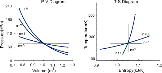
P.Vn=C2
Where C2 and n are constants and n is called the polytropic index. The polytropic index characterizes the process, as summarized in Figure 1, and is given by
n = (Cp-C1) / (Cv-C1)
The equivalent pressure temperature and work relationships are as follows:
P (n-1)/n /T = C3 (NR/C21/n)
And
W=n/n-1 (P2V2-P1V1)
Many gas compression and expansion processes may be usefully approximated by a polytropic process. In each case, the polytropic coefficient must be determined experimentally by measurement of the heat and work transfer and the initial and final states.
Belt, Rowlinson, and Saville (1975) discuss the errors and inconsistencies which may arise when PVn = C2 is applied to non-ideal gases and vapours.
Numerical problem-
Question- Consider 1 kg1 kg of air at 32 C that is expanded by a reversible polytropic process with n=1.25 until the pressure is halved. Determine the heat transfer.
The specific heat constant volume for air is 0.1786 kJ/kg.K
Answer- Cn=Cv (n−k / n−1)
Where k is the heat capacity ratio.
Air is considered a diatomic ideal gas, so k = 1.4.
Cv =0.718kJ/kg∗K.
We know that
T2=T1(p2/p1)1−1/n
=305K∗ (0.5)0.2=265.52
Cn =0.718(−0.15/.25)
=−0.4308kJkg∗K
Q=m x Cn (T2−T1)=1kg∗(−0.4308)∗(265.5K−305K)
=17.02kJ
a) Definition of refrigeration
The Refrigerant is the working substance that flows through a refrigerator and is capable of absorbing heat from the source (which is at a lower temperature) and dissipate the same to the sink (which is a higher temperature than the source) either in the form of sensible heat (as in case of air refrigeration) or in the form of latent heat (as in the case of vapour Refrigeration) is called a refrigerant.
Type of refrigerant – There are two types of refrigerant
- Primary refrigerants (Refrigerants that directly take part in the refrigeration process)
- Secondary refrigerants (refrigerants that are first cooled by the primary refrigerants and then further used for cooling purpose
b) Vapour compression refrigeration cycle
Vapour compression system: Vapour-compression refrigeration, in which the refrigerant undergoes phase changes, is one of the many refrigeration cycles and is the most widely used method for air-conditioning of buildings and automobiles. It is also used in domestic and commercial refrigerators, large-scale warehouses for chilled or frozen storage of foods and meats, refrigerated trucks and railroad cars, and a host of other commercial and industrial services. Oil refineries, petrochemical and chemical processing plants, and natural gas processing plants are among the many types of industrial plants that often utilize large vapor-compression refrigeration systems.
Working Of Vapour Compression Refrigeration System:
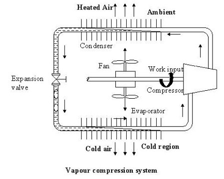
As shown in the figure the basic system consists of an evaporator, compressor, condenser, and expansion valve.
The refrigeration effect is obtained in the cold region as heat is extracted by the vaporization of refrigerant in the evaporator. The refrigerant vapour from the evaporator is compressed in the compressor to high pressure at which its saturation temperature is greater than the ambient or any other heat sink. Hence when the high pressure, the high-temperature refrigerant flows through the condenser, condensation of the vapour into liquid takes place by heat rejection to the heat sink. To complete the cycle, the high-pressure liquid is made to flow through an expansion valve. In the expansion valve the pressure and temperature of the refrigerant decrease. This low pressure and low-temperature refrigerant vapour evaporate in the evaporator taking heat from the cold region. It should be observed that the system operates on a closed cycle. The system requires input in the form of mechanical work. It extracts heat from a cold space and rejects heat to a high-temperature heat sink.
Vapour Compression Cycle -Working Diagram
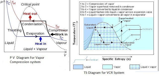 PV And TS Diagram For Vapour Compression System
Most of the modern refrigerators work on this cycle, in its simplest form, there are four fundamental operations required to complete one cycle.
(a) Compression
(b) Condensation
(c) Expansion
(d) Vaporization
a) Compression
The low-pressure Vapour in the dry state is drawn from the evaporator during the suction stroke of the compressor. During compression Stroke, the pressure and temperature increase until vapour temperature is greater than the temperature of the condenser cooling medium (air or water)
At point 1 in the diagram, the circulating refrigerant enters the compressor as a saturated vapour. From point 1 to point 2, the vapour is isentropically compressed (i.e., compressed at constant entropy) and exits the compressor as a superheated vapour.
b) Condensation
When the high-pressure refrigerant vapour enters the condenser heat flows from the condenser to the cooling medium thus allowing the vaporized refrigerant to return to the liquid state.
From point 2 to point 3, the vapour travels through part of the condenser which removes the superheat by cooling the vapour. Between point 3 and point 4, the vapour travels through the remainder of the condenser and is condensed into a saturated liquid. The condensation process occurs at essentially constant pressure.
c) Expansion
After the condenser, the liquid refrigerant is stored in the liquid receiver until needed. From the receiver, it passes through an expansion valve where the pressure is reduced sufficiently to allow the vaporization of liquid at a low temperature of about -10°C.
Between points 4 and 5, the saturated liquid refrigerant passes through the expansion valve and undergoes an abrupt decrease of pressure. That process results in the adiabatic flash evaporation and auto-refrigeration of a portion of the liquid (typically, less than half of the liquid flashes).
d) Vaporization
The low-pressure refrigerant vapour after expansion in the expansion valve enters the evaporator or refrigerated space where a considerable amount of heat IS absorbed by it and refrigeration is furnished.
Between points 5 and 1, the cold and partially vaporized refrigerant travels through the coil or tubes in the evaporator where it is vaporized by the warm air (from the space being refrigerated) that a fan circulates across the coil or tubes in the evaporator. The resulting refrigerant vapour returns to the compressor inlet at point 1 to complete the thermodynamic cycle.
c) Domestic refrigerator
The common type of domestic refrigerator has a cabinet shaped with a compressor, the condenser and receiver fitted in their basement. The expansion valve and evaporator coils are exposed in the storage cabinet with the pipings, carrying liquid refrigerant passing through the body.
Generally, methylene chloride, Freon-12, and Freon-11 are used as refrigerants.
Refrigeration is not only provided with double-walled cabinet packed with materials having high thermal insulation such as fiberglass, cork, or expanded rubber but also all around the inside of door flap soft rubber seal is used which makes the cabinet airtight.
Also, the door is provided with automatic closing mechanism door hinges are provided in such a way that the door flap when left in open position automatically comes to closing position due to gravity and as it approaches closing position it is attracted by the magnetic strip fitted behind the sealing rubber ring and thus the door is closed with a snap action.
All this is done to prevent leakage of atmospheric heat inside the refrigerator. The main precaution to be taken is that very hot things should not be put in the refrigerator if it is done it will quickly evaporate the refrigerant in evaporator coils producing a large vapour pressure increasing the duty of the compressor. It may damage the motor, which is short-time rated.
Parts of the refrigerator:
The refrigerator can be categorized into two categories: internal and external.
The internal parts are ones that carry out the actual working of the refrigerator. Some of the internal parts are located at the back of the refrigerator, and some inside the main compartment of the refrigerator.
1) Refrigerant:
The refrigerant flows through all the internal parts of the refrigerator. It is the refrigerant that carries out the cooling effect in the evaporator. It absorbs the heat from the substance to be cooled in the evaporator (chillier or freezer) and throws it into the atmosphere via a condenser. The refrigerant keeps on recirculating through all the internal parts of the refrigerator in the cycle.
2) Compressor: The compressor is located at the back of the refrigerator and in the bottom area. The compressor sucks the refrigerant from the evaporator and discharges it at high pressure and temperature. The compressor is driven by the electric motor and it is a major power-consuming device of the refrigerator.
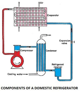
3) Condenser: The condenser is the thin coil of copper tubing located at the back of the refrigerator. The refrigerant from the compressor enters the condenser where it is cooled by the atmospheric air thus losing heat absorbed by it in the evaporator and the compressor. To increase the heat transfer rate of the condenser, it is finned externally.
4) Expansive valve or the capillary: The refrigerant leaving the condenser enters the expansion device, which is the capillary tube in the case of domestic refrigerators. The capillary is the thin copper tubing made up of some turns of the copper coil. When the refrigerant is passed through the capillary its pressure and temperature drop down suddenly.
5) Evaporator or chiller or freezer: The refrigerant at very low pressure and temperature enters the evaporator or the freezer. The evaporator is the heat exchanger made up of several turns of copper or aluminium tubing. In domestic refrigerators, the plate types of the evaporator are used as shown in the figure above. The refrigerant absorbs the heat from the substance to be cooled in the evaporator, gets evaporated, and is then sucked by the compressor. This cycle keeps on repeating.
6) Temperature control device or thermostat: To control the temperature inside the refrigerator there is the thermostat, whose sensor is connected to the evaporator. The thermostat setting can be done by the round knob inside the refrigerator compartment. When the set temperature is reached inside the refrigerator the thermostat stops the electric supply to the compressor and the compressor stops and when the temperature falls below a certain level it restarts the supply to the compressor.
7) Defrost system: The defrost system of the refrigerator helps to remove the excess ice from the surface of the evaporator. The defrost system can be operated manually by the thermostat button or there is an automatic system comprising of the electric heater and the timer. Those were some internal components of the domestic refrigerator; now let us see the external parts.
Externally visible parts of the Refrigerator
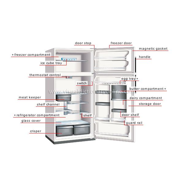
The external parts of the compressor are the parts that are visible externally and used for various purposes. The figure below shows the common parts of the domestic refrigerator and some of them are described below:
- Freezer compartment: The food items that are to be kept at freezing temperature are stored in the freezer compartment. The temperature here is below zero degrees Celsius so the water and many other fluids freeze in this compartment. If you want to make ice cream, ice, freeze the food, etc. they have to be kept in the freezer compartment.
- Thermostat control: The thermostat control comprises the round knob with the temperature scale that helps to set the required temperature inside the refrigerator. Proper setting of the thermostat as per the requirements can help save lots of refrigerator electricity bills.
- Refrigerator compartment: The refrigerator compartment is the biggest part of the refrigerator. Here all the food items that are to be maintained at a temperature above zero degree Celsius but in cooled condition are kept. The refrigerator compartment can be divided into some smaller shelves like meat keeper, and others as per the requirement.
- Crisper: The highest temperature in the refrigerator compartment is maintained in the crisper. Here one can keep the food items that can remain fresh even at the medium temperature like fruits, vegetables, etc.
- Refrigerator door compartment: There is some smaller subsections in the refrigerator main door compartment. Some of these are egg compartment, butter, dairy, etc.
- Switch: This is the small button that operates the small light inside the refrigerator. As soon the door of the refrigerator opens, this switch supplies electricity to the bulb and it starts, while when the door is closed the light from the bulb stops. This helps in starting the internal bulb only when required.
Working Principle of domestic refrigerator:
The refrigerator works on the vapour compression refrigeration cycle. The refrigerant vapour is first compressed in the compressor. The compressor is a special one known as the hermetic compressor. In this unit, the compressor is sealed casing along with an electrical motor to run. This sealing prevents leakage of refrigerant and lubrication oil. The pressure and temperature of the refrigerant increase after compression and is subsequently condensed in a condenser. In the condenser, the refrigerant rejects heat to a coolant and cools down, and finally gets condensed. The condensate is then allowed to pass through the capillary to reduce temperature and pressure by the expansion of refrigerant. The refrigerant is filtered before entering the capillary tube. The pressure of the refrigerant, when it leaves the capillary, is maintained above atmospheric and temperature corresponds to saturation temperature so that the refrigerant can absorb heat in the evaporator. The refrigerant enters the evaporator and is heated by the heat absorbed from the body or space thereby producing the refrigeration effect. The vapour refrigerant enters the compressor again and the cycle is completed.
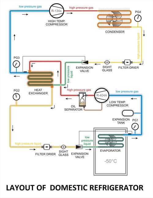
When power to the compressor is switched on, a humming sound is heard and the refrigerator is functional. The refrigerant flows through its circuit and ice is produced in the freezer. Frost, i.e., moisture from ambient air, gets deposited on the evaporator coil. Defrosting removes this frost. The water from defrosting is collected in a tray to be removed manually. Articles to be refrigerated are placed on shelves. Fruits and vegetables, which contain moisture, are stored at the base. The temperature here is around 8°C. Thus there are temperature gradients in the refrigerator, the negative temperature in the freezer, and the positive temperature at the base.
Applications of Refrigerator
As we studied in the above article a refrigerator is a device used to maintain a lower temperature than that of its surroundings by absorbing heat from the refrigerated space and reject it into the surrounding. In the past time, the main use of refrigerators was only produced ice which is used for many purposes but nowadays the application of the refrigerator increases day by day as the new technology develops.
Some major application of the refrigerator are given as follow
- The refrigerator is used in the processing and preservation of food items.
- The refrigerator is used in industrial applications like in the chemical and petroleum industry.
- Some special kinds of applications.
- In food processing and preservation
d) Air conditioning:
An air conditioner (AC) in a room or a car works by collecting hot air from a given space, processing it within itself with the help of a refrigerant and a bunch of coils, and then releasing cool air into the same space where the hot air had originally been collected. This is essentially how air conditioners work.
a) Window air conditioner:
The window air conditioner is sometimes referred to as a room air conditioner as well. It is the simplest form of an air conditioning system and is mounted on windows or walls. It is a single unit that is assembled in a casing where all the components are located.
This refrigeration unit has a double shaft fan motor with fans mounted on both sides of the motor. One at the evaporator side and the other at the condenser side. The evaporator side is located facing the room for cooling of the space and the condenser side outdoor for heat rejection. There is an insulated partition separating these two sides within the same casing.
Front Panel The front panel is the one that is seen by the user from inside the room where it is installed and has a user interfaced control be it electronically or mechanically. The older unit usually is of mechanical control type with rotary knobs to control the temperature and fan speed of the air conditioner.
The newer units come with electronic control system where the functions are controlled using remote control and touch panel with digital display.
The front panel has adjustable horizontal and vertical (some models) louvers where the direction of airflow is adjustable to suit the comfort of the users. The fresh intake of air called VENT (ventilation) is provided at the panel if the user would like to have a certain amount of fresh air from the outside.
The mechanical type is usually lower in price compared to the electronic type. If you just want to cool the room and are not too particular about aesthetic or additional functions, the mechanical type will do the work.
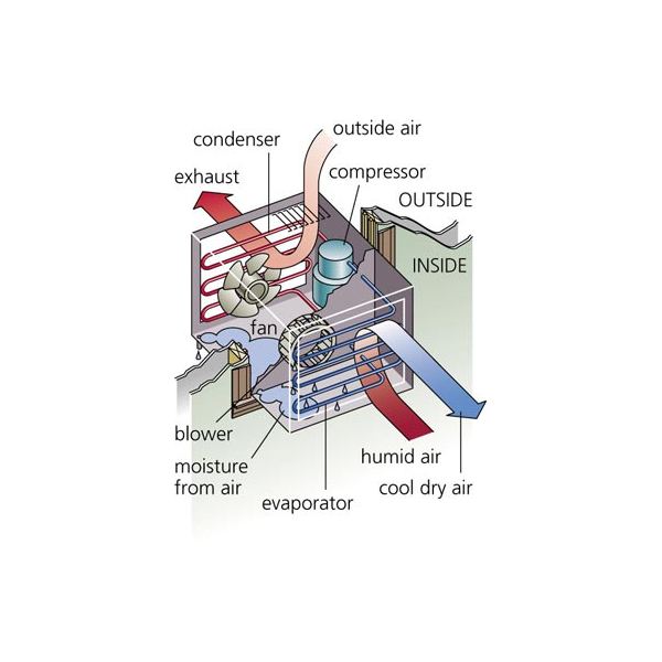
Indoor Side Components
The indoor parts of a window air conditioner include:
- Cooling Coil with an air filter mounted on it. The cooling coil is where the heat exchange happens between the refrigerant in the system and the air in the room.
- Fan Blower is a centrifugal evaporator blower to discharge the cool air to the room.
- Capillary Tube is used as an expansion device. It can be noisy during operation if installed too near the evaporator.
- Operation Panel is used to control the temperature and speed of the blower fan. A thermostat is used to sense the return air temperature and another one to monitor the temperature of the coil. Type of control can be a mechanical or electronic type.
- Filter Drier is used to removing the moisture from the refrigerant.
- Drain Pan is used to containing the water that condensates from the cooling coil and is discharged out to the outdoor by gravity.
The outdoor side parts include:
- The compressor is used to compress the refrigerant.
- Condenser Coil is used to rejecting heat from the refrigeration to the outside air.
- A propeller Fan is used in the air-cooled condenser to help move the air molecules over the surface of the condensing coil.
- Fan Motor is located here. It has a double shaft where the indoor blower and outdoor propeller fan are connected.
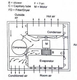
The low pressure and low-temperature refrigerant vapour from the evaporator are sucked by the compressor. The compressor compresses the vapour to high pressure and high temperature and discharges to the condenser. On the condenser, the refrigerant vapour condenses by dissipating heat to the cooling medium (air) the liquid refrigerant coming out of the condenser passes through the filter, dryer into the capillary tube where it is again throated back to the evaporated pressure. The low-pressure low temp liquid refrigerant then flows to the evaporator which boils off by extracting heat from the air to be circuited to the conditioned space.
b) Split air conditioner:
We know that the air conditioner mainly is of two types of windows and split. The split name was given to split system air conditioners for the very simple reason that they have two components.
There is a cabinet made of metal placed outside while the other part known as the air handler, containing the evaporator coil, is inside. The outdoor unit contains the condenser as well as the compressor, and both these parts are connected using a pipe or a duct. In the case of central air conditioning, there are some ducts used to connect different rooms, with the bigger unit placed outdoors. Almost all the central air conditioning units are split as they are more energy-efficient.
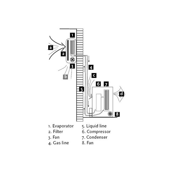
Parts of split air conditioner:
Mainly split ac divided into 2 parts of indoor units and outdoor units
Wall Mounted Indoor Unit
It is the indoor unit that produces the cooling effect inside the room. The indoor unit of the split air conditioner is a box-type housing in which all the important parts of the air conditioner are enclosed. The most common type of indoor unit is the wall-mounted type though other types like ceiling mounted and floor mounted are also used.
1) Evaporator Coil or the Cooling Coil:
The cooling coil is a copper coil made of number turns of the copper tubing with one or more rows depending on the capacity of the air conditioning system. The cooling coil is covered with aluminium fins so that the maximum amount of heat can be transferred from the coil to the air inside the room.
The refrigerant from the tubing at very low temperature and very low pressure enter the cooling coil. The blower absorbs the hot room air or the atmospheric air and in doing so the air passes over the cooling coil which leads to the cooling of the air. This air is then blown to the room where the cooling effect has to be produced. The air, after producing the cooling effect is again sucked by the blower, and the process of cooling the room continues.
After absorbing the heat from the room air, the temperature of the refrigerant inside the cooling coil becomes high and it flows back through the return copper tubing to the compressor inside the outdoor unit. The refrigerant tubing supplying the refrigerant from the outdoor unit to the indoor unit and that supplying the refrigerant from the indoor unit to the outdoor unit are both covered with insulation tape.
2) Air Filter:
The air filter is a very important part of the indoor unit. It removes all the dirt particles from the room air and helps to supply clean air to the room. The air filter in the wall-mounted type of indoor unit is placed just before the cooling coil. When the blower sucks the hot room air, it is first passed through the air filter and then through the cooling coil. Thus the clean air at low temperature is supplied into the room by the blower.
3) Cooling Fan or Blower:
Inside the indoor unit, there is also a long blower that sucks the room air or the atmospheric air. It is an induced type of blower and while it sucks the room air it is passed over the cooling coil and the filter due to which the temperature of the air reduces and all the dirt from it is removed. The blower sucks the hot and unclean air from the room and supplies cool and clean air back. The shaft of the blower rotates inside the bushes and it is connected to a small multiple speed motor, thus the speed of the blower can be changed. When the fan speed is changed with the remote it is the speed of the blower that changes.
4) Drain Pipe:
Due to the low-temperature refrigerant inside the cooling coil, its temperature is very low, usually much below the dew point temperature of the room air. When the room air is passed over the cooling due to the suction force of the blower, the temperature of the air becomes very low and reaches levels below its dew point temperature. Due to this, the water vapor present in the air gets condensed and dew or water drops are formed on the surface of the cooling coil. These water drops fall off the cooling coil and are collected in a small space inside the indoor unit. To remove the water from this space the drainpipe is connected from this space extending to some external place outside the room where water can be disposed of. Thus the drainpipe helps to remove dew water collected inside the indoor unit. To remove the water efficiently the indoor unit has to be tilted by a very small angle of about 2 to 3 degrees so that the water can be collected in the space easily and drained out. If this angle is in opposite direction, all the water will get drained inside the room. Also, if the tilt angle is too high, the indoor unit will shabby inside the room.
5) Louvers or Fins:
The cool air supplied by the blower is passed into the room through louvers. The louvers help to change the angle or direction in which the air needs to be supplied into the room as per the requirements. With louvers, one easily changes the direction in which the maximum amount of the cooled air has to be passed.
There are two types of louvers: horizontal and vertical. The horizontal louvers are connected to a small motor and their position can set by the remote control. One can set a fixed position for the horizontal louvers so that chilled air is passed in a particular direction only or one can keep it in rotation mode so that the fresh air is supplied throughout the room. The vertical louvers are operated manually and one can easily change their position as per the requirements. The horizontal louvers control the flow of air in upper and downward directions of the room, while vertical louvers control the movement of air in the left and right directions.
Outdoor Unit
As mentioned previously the outdoor unit is installed outside the room to be air-conditioned in the open space. In an outdoor unit lots of heat is generated inside the compressor and the condenser, hence there should be sufficient flow of the air around it. The outdoor unit is usually installed at the height above the height of the indoor unit inside the room though in many cases the outdoor is also installed at a level below the indoor unit.
The outdoor unit contains the important parts of the split AC like compressor, condenser, expansion valve, etc. Let us see these parts in more details:
1) Compressor:
The compressor is the most important part of any air conditioner. It compresses the refrigerant and increases its pressure before sending it to the condenser. The size of the compressor varies depending on the desired air conditioning load. In most domestic split air conditioners hermetically sealed type of compressor is used. In such compressors, the motor used for driving the shaft is located inside the sealed unit and it is not visible externally. External power has to be supplied to the compressor, which is utilized for compressing the refrigerant and during this process, lots of heat is generated in the compressor, which has to be removed by some means.
2) Condenser:
The condenser used in the outdoor unit of split air conditioners is the coiled copper tubing with one or more rows depending on the size of the air conditioning unit and the compressor. Greater the tonnage of the air conditioner and the compressor more are the coil turns and rows. The high temperature and high-pressure refrigerant from the compressor come in the condenser where it has to give up the heat. The tubing is made up of copper since its rate of conduction of heat is high. The condenser is also covered with aluminium fins so that the heat from the refrigerant can be removed at a faster rate.
3) Condenser Coil
Condenser Cooling Fan:
The heat generated within the compressor has to be thrown out else the compressor will get too hot in the long run and its motor coils will burn leading to complete breakdown of the compressor and the whole air conditioner. Further, the refrigerant within the condenser coil has to be cooled so that after expansion its temperature becomes low enough to produce the cooling effect. The condenser cooling fan is an ordinary fan with three or four blades and is driven by a motor. The cooling fan is located in front of the compressor and the condenser coil. As the blades of the fan rotate it absorbs the surrounding air from the open space and blows it over the compressor and the condenser with the aluminium fins thus cooling them. The hot air is thrown back to the open space and the circulation of air continues unhindered.
4) Expansion Valve:
The expansion valve is usually copper capillary tubing with several rounds of coils. In the split air conditioners of bigger capacities, thermostatic expansion valve is used which is operated electronically automatically. The high pressure and medium temperature refrigerant leaves the condenser and enters the expansion valve, where its temperature and pressure drops suddenly.
Working of split AC:
The outdoor unit of a split system air conditioner contains the refrigerant. The refrigerant is gas-pressurized into the compressor. There are many ducts or tubes in a ducted air conditioning unit through which the gas passes. This later condenses into liquid form.
This liquid then passes through the expansion joint and gets converted into a gaseous state. This releases a large amount of heat in the process.
The resultant gas is used for cooling the air at a very low temperature and hence called the refrigerant. This is a cyclic process that continues as the gas flows back into the compressor. The air of your room passes through the cavity containing evaporator coils. These coils contain gas at extremely low temperatures, thus cooling the air.
The thermostat present inside the air conditioning unit controls the temperature and the air continues to stay in the evaporator area till the desired temperature is obtained. It is then blown into the room.
Thus, your split system air conditioner sucks in the warm air and lowers its temperature before blowing it back into the room. The moisture inside the room condenses in the process, which is then removed through a drain pipe present in the outdoor unit.
References:
1. Engineering Thermodynamics, P K Nag, The Tata McGraw-Hill Companies
2. Mechanical Engineering Design, Joseph E Shigley, Charles R Mischke, The Tata McGraw- Hill Companies
3. Production Technology Vol. I & II, O.P. Khanna, Dhanpat Ray Publications