UNIT 3
PUMP, COMPRESSOR, TURBINE
CONTENT
I) Reciprocating pumps:
Reciprocating pump is a positive displacement pump where certain volume of liquid is collected in enclosed volume and is discharged using pressure to the required application. Reciprocating pumps are more suitable for low volumes of flow at high pressures.
It is very important part of the ships machinery and any other industry which is present in the world. High pressure is the main characteristic of this pump and this high pressure output are being used in places like starting of the engine or you can say the building of pressure in the fluids.
But there are used in limited application because they require lot of maintenance. These pumps are positive displacements pumps and that is the reason they do not require any type of priming for their functioning in the starting period of the pump.
Parts of Reciprocating Pump:
The Parts of Reciprocating Pump are as follows.
- Water Sump
- Strainer
- Suction Pipe
- Suction Valve
- Cylinder
- Piston and Piston rod
- Crank and Connecting rod
- Delivery valve
- Delivery pipe
The explanation for the parts of Reciprocating pump are as follows.
- Water Sump:
It is the source of water. From the sump, water is to be transported to the delivery pipes by the usage of the piston.
II. Strainer:
It acts as a mesh that can screen all the dirt, dust particles, etc. from the sump. If there is no strainer, then the dirt or dust also enters into the cylinder which can jam the region and affects the working of the pump.
III. Suction Pipe:
The main function of the suction pipe is to collect the water from the sump and send it to the cylinder via a suction valve. The suction pipe connects the water sump and the cylinder.
IV. Suction Valve:
It is a non-return valve which means it can take the fluid from the suction pipe and send it to the cylinder but cannot reverse the water back to it. In the sense, the flow is unidirectional.
This valve opens only during the suction of fluid and closes when there is a discharge of fluid to outside.
V. Cylinder:
It is a hollow cylinder made of cast iron or steel alloy and it consists of the arrangement of piston and piston rod.
VI. Piston and Piston rod:
For suction, the piston moves back inside the cylinder and for discharging of fluid, the piston moves in the forward direction.
The Piston rod helps the piston to move in a linear direction i.e. either the forward or the backward directions.
VII. Crank and Connecting rod:
For rotation, the crank is connected to the power source like engine, motor, etc. whereas the connecting rod acts as an intermediate between the crank and piston for the conversion of rotary motion into linear motion.
VIII. Delivery Pipe:
The function of the delivery pipe is to deliver the water to the desired location from the cylinder.
IX. Delivery valve:
Similar to the suction valve, a delivery valve is also a Non-return valve. During suction, the delivery valve closes because the suction valve is in opening condition and during Discharge, the suction valve is closed and the delivery valve Is opened to transfer the fluid.
Working Principle of Reciprocating Pump:
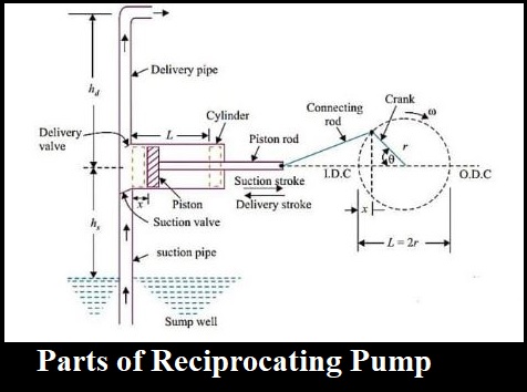
When the power supply is given to the reciprocating pump, the crank rotates through an electric motor. The angle made by the crank is responsible for the movement of the piston inside the cylinder. By referring to the above diagram, the piston moves towards the extreme left of the cylinder when the crank meets position A i.e. θ=0.
Similarly, the piston moves towards the extreme right of the cylinder when the crank meets the position C i.e. θ=180.
A partial vacuum in the cylinder takes place when the piston movement is towards the right extreme position i.e. (θ=0 to θ=180.) and that makes the liquid enter into the suction pipe. This is due to the presence of atmospheric pressure on the sump liquid which is quite less than the pressure inside the cylinder. Therefore, due to the difference in pressure, the water enters into the cylinder through a non-return valve.
The water which stays in the volume of the cylinder has to be sent to the discharge pipe via discharge valve and this can be done when the crank is rotating from C to A i.e. (θ=180 to θ=360) which moves the piston in the forward direction. Due to the movement of the piston in a forward direction, the pressure increases inside the cylinder which is greater than the atmospheric pressure.
This results in the opening of the delivery valve and closing of the suction valve. Once the water comes into the delivery valve, it cannot move back to the cylinder because it is a unidirectional valve or non-return valve.
From there, it enters into the delivery pipe so that it can be sent to the required position. Therefore, in this way, the water is sucked and discharged from the sump to the desired location through the piston inside the cylinder.
Reciprocating Pump Advantages:
1) This pump is self-priming – Not require filling the cylinders by starting.
2) This pump can work in wide pressure range.
3) Priming is not necessary in pump.
4) Provide elevated suction lift.
5) They are use for air also.
6) No priming is needed in the Reciprocating pump compared to the Centrifugal pump.
7) It can deliver liquid at high pressure from the sump to the desired height.
8) It exhibits a continuous rate of discharge.
9) It can work due to the linear movement of piston whereas the centrifugal pump works on the rotary velocity of the impeller.
Reciprocating Pump Disadvantages:
1. Flow is not consistent, so we have to fit a bottle at equally ends.
2. Flow is extremely less and cannot use for high flow process.
3. High wear and tear, so need lot maintenance.
4. Early price is much more in this pump.
5. Additional heavy and large in shape.
6. Low discharging capacity
7. The maintenance cost is very high due to the presence of a large number of parts.
8. The initial cost of this pump is high.
9. Viscous fluids are difficult to pump.
Applications of Reciprocating Pump:
The applications of Reciprocating Pump are as follows.
- Gas industries
- Petrochemical industries
- Oil refineries
- Vehicle water servicing centers etc.
- Oil drilling operations
- Pneumatic pressure systems
- Light oil pumping
- Feeding small boilers condensate return.
II) Centrifugal pump:
Centrifugal pump is a hydraulic machine which converts mechanical energy into hydraulic energy by the use of centrifugal force acting on the fluid. These are the most popular and commonly used type of pumps for the transfer of fluids from low level to high level. Its is used in places like agriculture, municipal (water and wastewater plants), industrial, power generation plants, petroleum, mining, chemical, pharmaceutical and many others.
Pumps are the mechanical devices that convert mechanical energy into hydraulic energy. They are generally used to raise the water or other fluids from lower elevation to higher elevation. So pumps are generally classified into centrifugal pump and positive displacement pump. Centrifugal pumps are non- positive displacement pumps. They work on the principle of centrifugal action.
The Main parts of Centrifugal Pump are:
1. Impeller
It is a wheel or rotor which is provided with a series of backward curved blades or vanes. It is mounded on the shaft which is coupled to an external source of energy which imparts the liquid energy to the impeller there by making it to rotate.
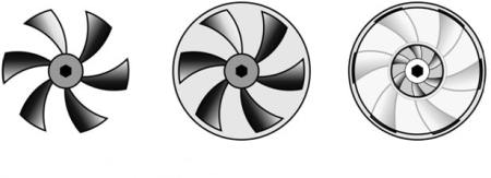
Fig 2: Open, Semi Enclosed and Enclosed Impeller.
Impellers are divided into following types,:
a) Based on direction of flow:
1) Axial-flow: – the fluid maintains significant axial-flow direction components from the inlet to outlet of the rotor.
2) Radial-flow: – the flow across the blades involves a substantial radial-flow component at the rotor inlet, outlet and both.
3) Mixed-flow: – there may be significant axial and radial flow velocity components for the flow through the rotor row.
b) Based on suction type:
1) Single suction: – liquid inlet on one side.
2) Double suction: – liquid inlet to the impeller symmetrically from both sides.
c) Based on mechanical construction:
1) Closed: – shrouds or sidewall is enclosing the vanes.
2) Open: – no shrouds or wall to enclose the vanes.
3) Semi–open or vortex type.
2. Casing
It is a pipe which is connected at the upper end to the inlet of the pump to the centre of impeller which is commonly known as eye. The double end reaction pump consists of two suction pipe connected to the eye from both sides. The lower end dips into liquid in to lift. The lower end is fitted in to foot valve and strainer.
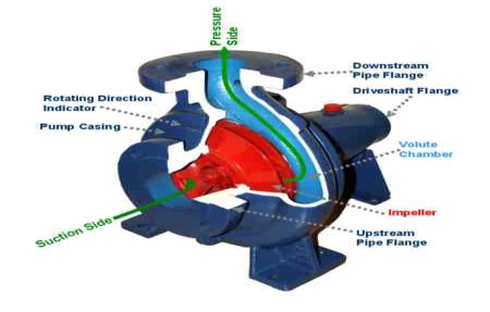
Fig 3: Main Components of Centrifugal Pump.
Commonly three types of casing are used in centrifugal pump are –
1) Volute casing: – It is spiral type of casing in which area of flow increase gradually. The increase in area of flow decreases the velocity of flow and increases the pressure of water.
2) Vortex casing: – if a circular chamber is introduced between casing and the impeller, the casing is known as vortex casing.
3) Casing with guide blades: – the impeller is surrounded by a series of guide blades mounted on a ring know as diffuser.
3. Delivery Pipe
It is a pipe which is connected at its lower end to the out let of the pump and it delivers the liquid to the required height. Near the outlet of the pump on the delivery pipe, a valve is provided which controls the flow from the pump into delivery pipe.
4. Suction Pipe with Foot Valve and Strainer
Suction pipe is connected with the inlet of the impeller and the other end is dipped into the sump of water. At the water end, it consists of foot value and strainer. The foot valve is a one way valve that opens in the upward direction. The strainer is used to filter the unwanted particle present in the water to prevent the centrifugal pump from blockage.
Working of Centrifugal Pump:
Water is drawn into the pump from the source of supply through a short length of pipe (suction pipe). Impeller rotates; it spins the liquid sitting in the cavities between the vanes outwards and provides centrifugal acceleration with the kinetic energy.
This kinetic energy of a liquid coming out an impeller is harnessed by creating a resistance to flow. The first resistance is created by the pump volute (casing) that catches the liquid and shows it down.
In the discharge nozzle, the liquid further decelerates and its velocity is converted to pressure according to BERNOULLI’S PRINCIPAL.
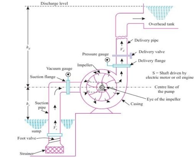
Let us understand in detail, how a Centrifugal pump works. Centrifugal pumps are used to induce flow or raise a liquid from a low level to a high level. These pumps work on a very simple mechanism. A centrifugal pump converts rotational energy, often from a motor, to energy in a moving fluid.
The two main parts that are responsible for the conversion of energy are the impeller and the casing. The impeller is the rotating part of the pump and the casing is the airtight passage which surrounds the impeller. In a centrifugal pump, fluid enters into the casing, falls on the impeller blades at the eye of the impeller, and is whirled tangentially and radially outward until it leaves the impeller into the diffuser part of the casing. While passing through the impeller, the fluid is gaining both velocity and pressure
Efficiency of centrifugal pump:-
The efficiency of a centrifugal pump can be defined as the ratio of the output power (water) to the input power (shaft). It can be demonstrated by using the following equation.
Ef = PW / PS
Where,
Ef is efficiency
Pw is the water power
Ps is the shaft power
Some other efficiencies are given below:
- Mechanical efficiency: – It is ratio of the impeller power to the shaft power.
- Hydraulic efficiency: – It is ratio of the manometric head to the Euler head.
- Volumetric efficiency:- It is ratio of the actual to the theoretical discharge.
- Overall efficiency: – It is ratio of the water power to the shaft power.
Applications of Centrifugal Pumps:
The fact that centrifugal pumps are the most popular choice for fluid movement makes them a strong contender for many applications. They are used across numerous industries. Supplying water, boosting pressure, pumping water for domestic requirements, assisting fire protection systems, hot water circulation, sewage drainage and regulating boiler water are among the most common applications. Outlined below are some of the major sectors that make use of these pumps:
- Oil & Energy - pumping crude oil, slurry, mud; used by refineries, power generation plants
- Industrial & Fire Protection Industry - Heating and ventilation, boiler feed applications, air conditioning, pressure boosting, fire protection sprinkler systems.
- Waste Management, Agriculture & Manufacturing - Wastewater processing plants, municipal industry, drainage, gas processing, irrigation, and flood protection
- Pharmaceutical, Chemical & Food Industries - paints, hydrocarbons, petrochemical, cellulose, sugar refining, food and beverage production
- Various industries (Manufacturing, Industrial, Chemicals, Pharmaceutical, Food Production, Aerospace etc.) - for the purposes of cryogenics and refrigerants.
Advantages of Centrifugal Pumps
The centrifugal pumps advantages include the following.
a) These pumps do not include drive seals that reduce leakage risk.
b) These pumps are used to pump out harmful and risky fluids.
c) These pumps have magnetic coupling that can be damaged simply in overload situations as well as protects the pump from external forces.
d) The motor and pump are separated from each other so heat transfer is impossible from the motor to pump.
e) These pumps generate low friction.
Disadvantages of Centrifugal Pumps
The centrifugal pumps disadvantages include the following.
a) The energy loss can be occurred due to the coupling that generates some magnetic resistance.
b) Once the intense load occurs, possibilities are there for the coupling fall.
c) If fluids with ferrous particles are pumped out, then rust occurs & over the time pumps stops working.
d) When the flow of liquid is less through the pump, then the overheating can occur
Compressor:
The usage of compressed air is not limited only to industries, but they are also used in manufacturing, welding, constructions, power plants, ships, automobile plants, painting shops, and for filling breathing apparatus too. Thus there are so many types of air compressors used specifically for the above purposes
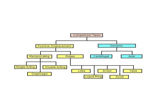
Types of Air Compressors:
Compressors are classified in many ways out of which the common one is the classification based on the principle of operation.
Types of Compressors:
1. Positive Displacement and
2. Roto-Dynamic Compressors.
Positive displacement compressors cab be further divided into Reciprocating and rotary compressors.
Under the classification of reciprocating compressors, we have
- In-line compressors,
- “V”-shaped compressors,
- Tandem Piston compressors.
- Single-acting compressors,
- Double-acting compressors,
- Diaphragm compressors.
The rotary compressors are divided into
- Screw compressors,
- Vane type compressors,
- Lobe and scroll compressors and other types.
Under the Roto-dynamic compressors, we have
- Centrifugal compressors, and the
- Axial flow compressors.
The compressors are also classified based on other aspects like
- Number of stages (single-stage, 2-stage and multi-stage),
- Cooling method and medium (Air cooled, water cooled and oil-cooled),
- Drive types ( Engine driven, Motor driven, Turbine driven, Belt, chain, gear or direct coupling drives),
- Lubrication method (Splash lubricated or forced lubrication or oil-free compressors).
- Service Pressure (Low, Medium, High)
I) Reciprocating compressor:
A reciprocating compressor is a positive-displacement machine that uses a piston to compress a gas and deliver it at high pressure.
This type of compressor uses piston-cylinder arrangement to compress the air. Whenever something moves back and forth it is considered as moving in reciprocating motion. Similarly in this type piston moves back and forth inside the cylinder and compress the air. There are two sets of valves that take care of air intake and exhaust.
The compressor takes inside successive amount of volume of air from intake valve and confined it in closed surface at that time piston moves downward with the closure of intake valve. Then there is compression of air by reducing its volume .Now the piston moves upward and compress the air and then displace the compressed air through exhaust valve. And then again intake take place and cycle repeat itself
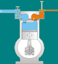
This type of compressor also called positive displacement machines. They are available in both as lubricated and oil-free.
The reciprocating compressor is single acting when the compressing is accomplished using only one side of piston and double acting when both the sides of piston used.
Major components of reciprocating compressor:
Reciprocating compressors are available in a variety of designs and arrangements. Major components in a typical reciprocating compressor are
- Frame
- Cylinders
- Distance Piece
- Piston
- Piston rings
- Cross Head
- Crankshaft
- Connecting Rod
- Valve
- Bearings
Some important parts are explained below:
Frame
The frame is a heavy, rugged housing containing all the rotating parts and on which the cylinder and crosshead guide is mounted. Compressor manufacturers rate frames for a maximum continuous horsepower and frame load .
Separable compressors are usually arranged in a balanced-opposed configuration characterized by an adjacent pair of crank throws that are 180 degrees out of phase and separated by only a crank web. The cranks are arranged so that the motion of each piston is balanced by the motion of an opposing piston.
Integral compressors typically have compressor and engine-power cylinders mounted on the same frame and are driven by the same crankshaft. Cylinders in integral compressors are usually arranged on only one side of the frame (i.e., not balanced-opposed).
Cylinder
The cylinder is a pressure vessel that contains the gas in the compression cycle. Single-acting cylinders compress gas in only one direction of piston travel. They can be either head end or crank end. Double-acting cylinders compress gas in both directions of piston travel .Most reciprocating compressors use double-acting cylinders.
Distance piece
The distance piece provides separation between the compressor cylinder and the compressor frame
Crankshaft
The crankshaft rotates around the frame axis and drives the connecting rod, piston rod, and piston.
Connecting rod connects the crankshaft to the crosshead pin
Crosshead converts the rotating motion of the connecting rod to a linear, oscillating motion that drives the piston
Piston rod connects the crosshead to the piston.
Piston and piston ring
The piston is located at the end of the piston rod and acts as the movable barrier in the compressor cylinder. Selection of material is based on strength, weight, and compatibility with the gas being compressed. The piston is usually made of a lightweight material such as aluminium or from cast iron or steel with a hollow centre for weight reduction. Thermoplastic wear (or rider) bands often are fitted to pistons to increase ring life and reduce the risk of piston-to-cylinder contact. Cast iron usually provides a satisfactorily low friction characteristic, eliminating the need for separate wear bands.
Wear bands distribute the weight of the piston along the bottom of the cylinder or liner wall. Piston rings minimize the leakage of gas between the piston and the cylinder or liner bore. Piston rings are made of a softer material than the cylinder or liner wall and are replaced at regular maintenance intervals. As the piston passes the lubricator feed hole in the cylinder wall, the piston ring gathers oil and distributes it over the length of the stroke.
Bearings
Bearings located throughout the compressor frame assure proper radial and axial positioning of compressor components. Main bearings are fitted in the frame to properly position the crankshaft. Crank pin bearings are located between the crankshaft and each connecting rod. Wrist pin bearings are located between each connecting rod and crosshead pin. Crosshead bearings are located at the top and bottom of each crosshead.
Most of the bearings in reciprocating compressors are hydrodynamic lubricated bearings. Pressurized oil is supplied to each bearing through oil supply grooves on the bearing surface. The grooves are sized to ensure adequate oil flow to prevent overheating.
Compressor valves
The essential function of compressor valves is to permit gas flow in the desired direction and to block all flow in the opposite (undesired) direction. Each operating end of a compressor cylinder must have two sets of valves. The set of inlet (suction) valves admits gas into the cylinder. The set of discharge valves is used to evacuate compressed gas from the cylinder. The compressor manufacturer normally specifies valve type and size.
Working of reciprocating compressor:
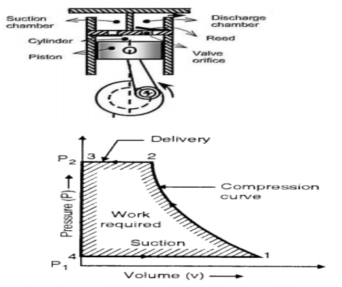
In single stage reciprocating air compressor, the entire compression is carried out in a single cylinder. The opening & closing of a simple check valve (plate or spring valve) depends upon the difference in pressure, if mechanically operated valves are used for suction & discharge then their functioning is controlled by cams. The weight of air in the cylinder will be zero when the piston is at top dead centre. At this position, you have to neglect clearance volume.
When piston starts moving downwards, the pressure inside the cylinder falls below atmospheric pressure& suction valve/inlet valve opens. The air is drawn into the cylinder through a suction filter element. This operation is known as suction stroke.
When the piston moves upwards, compresses the air in cylinder & inlet valve closes when the pressure reaches atmospheric pressure. Further compression follows as the piston moves towards the top of its stroke until when the pressure in the cylinder exceeds that in the receiver. This is compression stroke of a compressor. At the end of this stroke discharge/delivery valve opens & air is delivered to a receiver.
Advantages and disadvantages of reciprocating compressor
Advantages:
1. High thermal efficiency and low power consumption per unit
2. Convenient processing, low material requirements and low cost
3. Simple device system
4. Early design and production, mature manufacturing technology
5. Wide range of application
Disadvantages:
1. There are many moving parts, complex structure, heavy maintenance work and high maintenance cost
2. Speed Limited
3. The wear of piston ring, the wear of cylinder and the transmission mode of belt make the efficiency drop rapidly
4. Loud noise
5. The backward control system does not meet the needs of chain control and unattended, so although the price of piston machine is very low, it is often not accepted by users.
Applications:
The reciprocating compressor generally seen where there is requirement of high pressure and low flow(or discontinuous flow up to 30 bars).Mostly where the air is used for hand-tools, cleaning dust, small paint jobs, commercial uses, for examples-
1. In spray painting shop.
2. In workshop for cleaning machines.
3. For operation of pneumatic tool like rock drill, vibrator etc.
4. In automobile service station to clean vehicle.
5. To drive air motors in coal mines.
6. Food and beverage industry
II) Vane type compressors:
Vane Compressor is also known as Rotary Vane Compressor or Sliding Vane compressor. It was invented by Charles C. Barnes of Canada. He patented it on 16 June 1874. Vane Compressor is one of the most widely used products in today’s world. They serve a wide range of industries. It used centrifugal motion to generate compressed air. It is generally used for capacities up to 150 metre cube/min and for pressure ratio up to 8:5. They are very popular in automotive and hydraulic applications.
Construction:
Vane Compressor consists of a cylindrical rotor eccentrically placed in the casing. This casing has intake and delivery openings which are also known as inlet and outlet port. The inlet port of the casing is bigger as compared to the outlet port of the casing. Rotor has a drum in its centre.
This drum rotates eccentrically with respect to the casing. This rotor has several radial slots in it. Each radial slot has a vane fitted in it which is spring loaded.

These vanes are made of steel or synthetic fibrous material. If the compressor is oil-lubricated, there will be a thin layer of oil in between the vane and housing.
The spaces between adjacent vanes form pockets of decreasing volume from a fixed inlet port to a fixed discharge port.
Larger the number of vanes smaller the leakage of air due to small pressure difference prevailing between the adjacent spaces around the rotor.
High pressure ratio requires large number of vanes ( 20 – 30 ). For a given pressure ratio, cane compressor requires less work input than that for roots blower.
Working:-
When the rotor rotates, vanes of the rotor move outward toward the casing due to centrifugal force experienced by them, until they touch the casing.
The rotor of the vane compressor rotates in the anti-clockwise direction.
When the vanes reaches the position where the distance between the rotor drum and casing is less the spring in the vanes compresses to maintain contact with the casing. As the spring compresses the space between the two adjacent vanes also decreases.
Similarly, when the vanes reach the position where the distance between the rotor drum and casing is more the spring in the vanes expands to maintain contact with the casing.
As the spring expands the space between the two adjacent vanes also increases.
When the vanes move downward the space between two adjacent vanes increases also space between rotor drum and casing increases which create vacuum. Thus the gas is drawn in from the suction opening
Near the inlet of the vane compressor, the space between two adjacent vanes increases due to increased distance between rotor drum and casing.
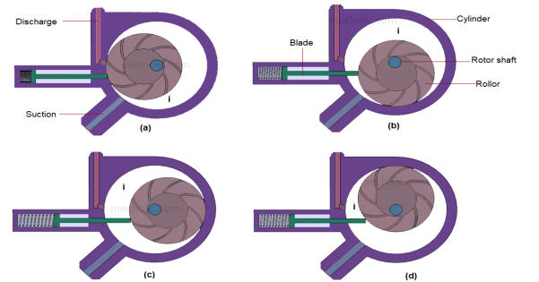
As the space increases between two adjacent vanes, vacuum is created near the inlet of vane compressor.
Due to the vacuum, the suction starts and the gas is drawn in from the inlet of the compressor. After that, as the rotor continues to rotate the compression of the entrapped gas starts due to a decrease in the space between adjacent vanes. As the space between vanes decreases, the volume of the gas decreases and the gas gets compressed.
After that, the high pressure gas which is compressed gets discharged from the outlet of the vane compressor. Nearly half of the rise of pressure of the gas is developed during the compression which is reversible compression. The remaining pressure rise occurs when the compressed gas is released from the outlet of the compressor.
Advantages of Vane Compressor:
1) It creates a good vacuum for suction.
2) Vane Compressor works well for continuous air supplied.
3) High pressure and high power compression are possible with vane compressor.
4) Vane compressors have a longer life expectancy.
5) They are ideally suited for moderate pressure using applications.
Disadvantages of Vane Compressor:
1) The vibration happens during the reciprocation of the cylinder.
2) Because of more number of moving parts maintenance cost is high.
Applications of Vane Compressor:
Vane Compressor has many applications. They serve a wide range of industries. Some of the applications of the vane compressor are:-
1) They are used in agriculture for operating farm equipment, material conveying, etc.
2) Used in the auto body paint shop for paint pump operation.
3) Used in tire and wheel shop for tire inflation.
4) Used in Dry Cleaning.
5) Used in the operation of air knives for cutting and peeling.
6) It is used in welding operations and air-operated metal and woodworking tools.
Turbine: A turbine or from the Latin turbo, a vortex, related to the Greek meaning "turbulence" is a rotary mechanical device that extracts energy from a fluid flow and converts it into useful work.
I) Kaplan turbine:
Kaplan Turbine is an axial reaction flow turbine and has adjustable blades.
If water flows parallel to the axis of the rotation of the shaft, the turbine is known as the axial flow turbine. And if the head of the inlet of the turbine is the sum of pressure energy and kinetic energy during the flow of water through a runner a part of pressure energy is converted into kinetic energy, the turbine is known as reaction turbine. For the axial flow reaction turbine, the shaft of the turbine is vertical. The lower end of the shaft is made larger which is known a hub or boss.
The vanes are fixed on the hub and hence hub acts as a runner for axial flow reaction turbine. It was developed in 1913 by the Austrian professor Viktor Kaplan. The Kaplan turbine was an evolution of the Francis turbine.
Its invention allowed efficient power production in the low head application that was not possible with Francis turbine. Kaplan turbine is now widely used throughout the world for high-flow, low head power production.
The Kaplan turbine is an axial flow reaction turbine because the water is moving in the axial direction.
Operating parameters of Kaplan Turbine
Head: 10 m to 70 m
RPM: 54.5 to 429
Power output: 5 MW to 200 MW
Runner diameter: 2 m to 11 m
Main Parts of Kaplan Turbine:
A Kaplan Turbine is consisted of:
- Scroll casing,
- Guide vane mechanism,
- Hub with vanes or runner of the turbine, and
- Draft tube.
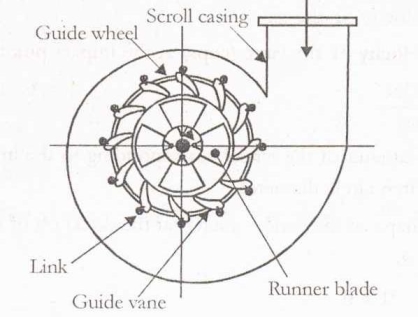
1) Scroll casing:
The scroll casing is a spiral type of casing that decreases the cross-section area. First, the water from the penstocks enters the scroll casing and then moves to the guide vanes. From the guide vanes, the water turns through 90° and flows axially through the runner.
The scroll casing protects the runner, runner blades, guide vanes and other internal parts of the turbine from external damage to the turbine.
2) Guide Vanes Mechanism:
This is the only controlling part of the whole turbine which opens and closes depending upon the demand of power requirement, the more power output requirements, it opens wider to allow more water to hit the blades of the rotor.
And when low power output requires, it closes to cease the flow of water. When the guide vanes are absent then the turbine cannot work efficiently and so that the efficiency of the turbine decreases.
3) Hub with vanes or Runner of the turbine:
The term “Runner” in the Kaplan turbine plays an important role. The runner is the rotating part of the turbine in which helps in the production of electricity. The shaft is connected to the shaft of the generator. The runner of this turbine has a large boss on which its blades are attached and the blades of the runner are adjustable to an optimum angle of attack for maximum power output.
The blades of the Kaplan turbine have twist along its length. Twist along its length in the Kaplan turbine is provided because to have always the optimum angle of strike for all cross-section of blades and hence to achieve greater efficiency of the turbine.
4) Draft Tube:
At the exit of the runner of Reaction Turbine, the pressure available here is generally less than the atmospheric pressure. The water at the exit cannot be directly discharged to the tailrace. A tube or pipe is gradually increasing area and this is used for discharging water from the exit of the turbine to the tailrace.
So, the increasing area of the tube or pipe is called a Draft tube. One end of the draft tube is connected to the runner outlet and the other end is submerged below the level of water in the tail-race.
The main important point is that the Draft tube is used only in the Reaction turbine.
There are 4 types of draft tube:
- Simple Elbow Draft Tube
- Elbow with the varying cross-section
- Moody Spreading Draft Tube.
- Conical Diffuser or Divergent Draft Tube
Working Principle of the Kaplan Turbine:
Kaplan turbine is an axial flow reaction turbine. So the working fluid changes the pressure as it moves across the turbine and gives energy. Power recapitulates from both the Hydrostatic head and kinetic energy of the following water.
From the penstock, the water is coming to enter into the casing. Here flow pressure is not lost because the shape of casing is designed in such a way that it does not lose the flow. From the casing, the water is entering into the guide vane. Here rotor is attached so the water comes with much pressure and hence it rotates the runner.
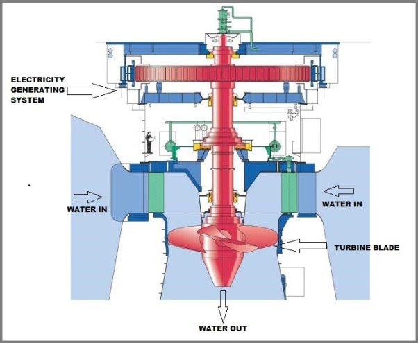
From the runner, the water enters into draft tube here pressure and kinetic energy decreases. The remaining kinetic energy gets converted into pressure energy and hence increases the pressure of water. Further rotation of the turbine is used to rotate the shaft of a generator and further used for the generation or production of electricity.
Advantages of the Kaplan Turbine:
- This turbine work more efficiently at low water head and high flow rates as compared with other turbines.
- This is smaller in size.
- The efficiency of the Kaplan turbine is very high as compares with other types of hydraulic turbines.
- The Kaplan turbine is easy to construct and
- The space requirement is less.
Disadvantages of Kaplan Turbine:
- The position of the shaft is only in the vertical direction.
- A large flow rate must be required.
- The main disadvantages are the cavitation process. Which occurs due to pressure drops in the draft tube.
- The use of the draft tube and proper material generally stainless steel for the runner blades may reduce the cavitation problem to a greater extent.
Applications of Kaplan Turbine:
- Kaplan turbines are widely used throughout the world for electric power production. They cover the lowest head hydro sites and are especially suited for high flow conditions.
- Inexpensive micro turbines are manufactured for individual power production with as little as two feet of head.
- Large Kaplan turbines are individually designed for each site to operate at the highest possible efficiency, typically over 90%.
- They are very expensive to design, manufacture and install but operate for decades.
II) Francis turbine:
The Francis turbine is a mixed flow reaction turbine. This turbine is used for medium heads with medium discharge. Water enters the runner and flows towards the centre of the wheel in the radial direction and leaves parallel to the axis of the turbine.
Turbines are subdivided into impulse and reaction machines. In the impulse turbines, the total head available is converted into the kinetic energy. In the reaction turbines, only some part of the available total head of the fluid is converted into kinetic energy so that the fluid entering the runner has pressure energy as well as kinetic energy. The pressure energy is then converted into kinetic energy in the runner.
The Francis turbine is a type of reaction turbine that was developed by James B. Francis. Francis turbines are the most common water turbine in use today. They operate in a water head from 40 to 600 m and are primarily used for electrical power production. The electric generators which most often use this type of turbine have a power output which generally ranges just a few kilowatts up to 800 MW
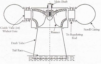
Parts Of Francis Turbine
Francis turbine consists mainly of the following parts
a) Spiral or scroll casing –
It is a closed passage whose cross-sectional area gradually decreases along the flow direction. The area is maximum at the inlet and nearly zero at the outlet.
b) Guide mechanism –
Guides vanes direct the water onto the runner at an angle appropriate to the design. The driving force on the runner is both due to impulse and reaction effects. The number if a runner blade usually varies between 16 and 24.
c) Runner and turbine main Shaft:
d) Draft tube:
It is a gradually expanding tube which discharges the water passing through the runner to the tailrace.
e) Penstock:
It is the large pipe which conveys water from the upstream of the reservoir to the turbine runner.
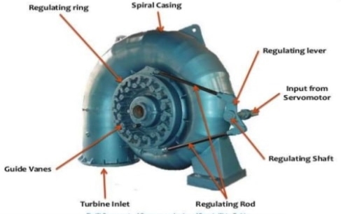
Spiral casing or scroll Casing:
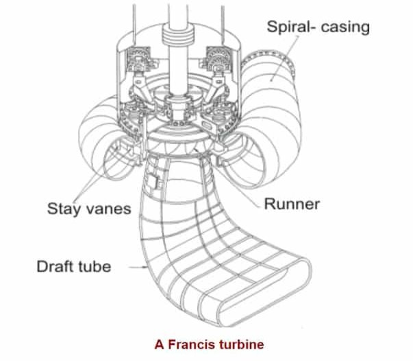
The casing of the Francis turbine is designed in a spiral form with a gradually increasing area. Most of these machines have vertical shafts although some smaller machines of this type have a horizontal shaft. The fluid enters from the penstock (pipeline leading to the turbine from the reservoir at high altitude) to a spiral casing that surrounds the runner.
This casing is known as scroll casing or volute. The cross-sectional area of this casing decreases uniformly along the circumference to keep the fluid velocity constant in magnitude along its path towards the stay vane. This is so because the rate of flow along the fluid path in the volute decreases due to continuous entry of the fluid to the runner through the openings of the stay vanes.
The casing is made of a cast steel, plate steel, concrete, or concrete and steel depending upon the pressure to which it is subjected. Out of these a plate steel scroll casing is commonly provided for turbines operating under 30 m or higher heads.
The advantages of this design are
i) Smooth and even distribution of water around the runner.
Ii) Loss of head due to the formation of eddies is avoided.
Iii) The efficiency of the flow of water to the turbine is increased.
In big units stay vanes are provided which direct the water to the guide vanes. The casing is also provided with inspection holes and a pressure gauge connection.
The selection of material for the casing depends upon the head of water to be supplied
For a head up to 30 meters —concrete is used.
For a head from 30 to 60 meters — welded rolled steel plates are used.
For a head of above 90 meters. — Cast steel is used.
Guide Mechanism
It consists of a stationary circular wheel all around the runner of the turbine. The stationary guide vanes are fixed on the guide mechanism. The guide vanes allow the water to strike the vanes fixed on the runner without shock at the inlet.
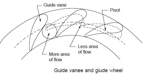
The guide vanes (also called as wicket gates) are fixed between two rings. This arrangement is in the form of a wheel and called a guide wheel. Each vane can be rotated about its pivot canter.
The opening between the vanes can be increased or decreased by adjusting the guide wheel. The guide wheel is adjusted by the regulating shaft which is operated by a governor. The guide blades rest on pivoted on a ring and can be rotated by the rotation of the ring, whose movement is controlled by the governor. In this way the area of blade passage is changed to vary the flow rate of water according to the load so that the speed can be maintained constant. The variation of area between guide blades is illustrated in Figure
The guide mechanism provides the required quantity of water to the runner depending upon the load conditions. The guide vanes are in general made of cast steel.
Guide Mechanism For Francis Turbine
Runner and Turbine Main Shaft:
Runner is a circular wheel on which a series of radial curved vanes are fixed. The surfaces of the vanes are made very smooth. The radial curved vans are so shaped that the water enters and leaves the runner without shocks. The flow in the runner of a modern Francis turbine is partly radial and partly axial.
The runners may be classified as
i) Slow
Ii) Medium
Iii) Fast
The runner may be cast in one piece or made of separate steel plates welded together. The runner made of CI for small output, cast steel, or stainless steel or bronze for large output. The runner blades should be carefully finished with a high degree of accuracy. The runner may be keyed to the shaft which may be vertical or horizontal. The shaft is made of steel and is forged it is provided with a collar for transmitting the axial thrust.
Draft Tube:
The pressure at the exit of the runner of a reaction turbine is generally less than atmospheric pressure. The water at the exit cannot be directly discharged to the tailrace. A tube or pipe of the gradually increasing area is used for discharging water from the exit of the turbine to the tailrace. This tube of increasing area is called the draft tube
The water after doing work on the runner passes on to the tall race through a tube called a draft tube. It is made of riveted steel plate or pipe or a concrete tunnel. The cross-section of the tube increases gradually towards the outlet. The draft tube connects the runner exit to the tailrace. This tube should be drowned approximately 1 meter below the tailrace water level.
Function of draft tube –
i) To decrease the pressure at the runner exit to a value less than atmospheric pressure and thereby increase the effective working head.
ii) To recover a part of electric energy into pressure head at the exit of the draft tube. This enables easy discharge to the atmosphere.
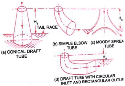
Types of draft tube:
i. Conical draft tube
ii. Simple elbow draft tube
iii. Moody spreading draft tube
iv. Elbow draft tube with circular cross-section at inlet and rectangular at outlet
(1) Conical Draft Tubes—
This is known as a tapered draft tube and used in all reaction turbines where conditions permit. It is preferred for low specific speed and Francis turbine. The maximum cone angle is 8° (a = 40°). The hydraulic efficiency is 90%.
(2) Simple Elbow Tubes-
The elbow type draft tube is often preferred in most of the power plants. If the tube is large in diameter; ‘it may be necessary to make the horizontal portion of some other section. A common form of section used is over or rectangular. It has low efficiency of around 60%.
(3) Moody Spreading Tubes-
This tube is used to reduce the whirling action of discharge water when the turbine runs at high speed under low head conditions. The draft tube has an efficiency of around 85%.
(4) Elbow with circular inlet and rectangular outlet—
This tube has circular cross-section at the inlet and rectangular section at the outlet. The change from the circular section to the rectangular section takes place in the bend from the vertical leg to the horizontal leg. The efficiency is about 85%.
Working of Francis turbine:
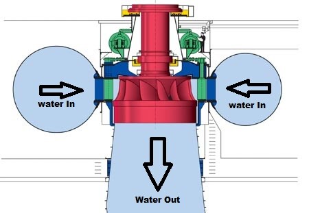
First, the water is allowed to enter into the spiral casing of the turbine, which guides the water through the stay vanes and guide vanes. The spiral case is kept here in decreasing diameter so that to maintain the flow pressure.
The stay vanes being stationary at their place removes the swirls from the water, which are generated due to flow through the spiral casing and tries it to make the flow of water more linear to be deflected by adjustable guide vanes.
The angle of guide vanes determines the angle of strikes of water at the runner blades thus make sure the output of the turbine. The runner blades are stationary and can-not pitch or change their angle. In short, the guide vane controls the power output of a turbine.
The performance and efficiency of the Francis turbine are dependent on the design of the runner blades.
In a Francis turbine, the runner blades are divided into two parts. The lower half is made in the shape of a small bucket so that it uses the impulse action of water to rotate the turbine.
The other or you can say the upper part of the blades uses the reaction force of water flowing through it. Thus, runner blades make use of both pressure energy and kinetic energy of water and rotate the runner most efficiently.
The water which is coming out of runner blades would lack both the kinetic energy and pressure energy, so we use the draft tube to recover the pressure as it advances towards tailrace, but still, we cannot recover the pressure to that extent that we can stop air to enter into the runner housing thus causing cavitation.
Efficiencies of Francis Turbine:
Hydraulic efficiency:
It is the ratio of work done on the wheel to the head of water (or energy) supplied to the turbine.
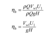
Mechanical efficiency:
It is a ratio of actual work available at the turbine to the energy imparted to the wheel.

Overall efficiency:
It is the measure of the performance of a turbine and the ratio of power produced by the turbine to the energy supplied to the turbine.

Blade efficiency:
Let’s see the velocity triangle of an Ideal Francis Turbine:
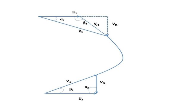
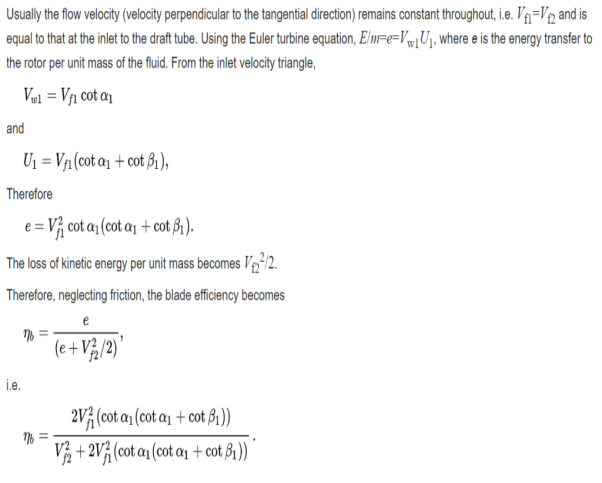
The formula of Power developed:

Degree of Reaction:
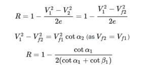
Advantage of Francis Turbine :
1. The difference in the operating head can be extra simply controlled in Francis turbine than in the Pelton wheel turbine.
2. The ratio of utmost and least operating head can even be two in the case of Francis Turbine.
3. The mechanical efficiency of the Pelton wheel decreases faster by wear than Francis turbine.
4. Francis turbine variation in operating head can be more simply controlled.
5. No head failure occurs still at the low discharge of water.
6. The size of the runner and generator is small.
7. Small changes in efficiency over time.
8. Operating head can be utilized even when the variation in tail water level is relatively large when compared to the total head.
Disadvantage of Francis Turbine:
1. The water which is not dirt-free can cause extremely rapid wear in high head Francis turbine.
2. As spiral casing is stranded, the runner is not simply available. Therefore dismantle is hard.
3. The repair and inspection is much harder reasonably.
4. Cavitation is an ever-present hazard.
5. Current losses are certain
6. Head 50 percent lower can be a harmful effect on the efficiency as well as cavitation danger becomes more serious.
Applications of Francis Turbine:
- This is the most efficient hydraulic turbine.
- Large Francis turbine is individually designed for the site to operate at the highest possible efficiency, typically over 90%.
- Francis type units cover a wide head range, from 20 to 700 M and their output varies from a few kilowatts 200 megawatt.
- In addition to electrical products and they may also be used for pumped storage; Where is Reservoir is filled by the turbine (acting as a pump) during low power demand, and then reversed and used to generate power during peak demand.
- Francis turbine may be designed for a wide range of heads and flows. This, along with their high efficiency, has made them the most widely used turbine in the world.
III) Pelton wheel turbine:
Pelton Turbine is a Tangential flow impulse turbine in which the pressure energy of water is converted into kinetic energy to form high speed water jet and this jet strikes the wheel tangentially to make it rotate. It is also called as Pelton Wheel.
- The turbine capable of working under the high potential head of water is the Pelton Wheel Turbine which works on the head greater than 300 m.
- The runner consists of a circular disc with a suitable number of double semi-ellipsoidal cups known as buckets which are evenly spaced around its Periphery.
- One or more nozzles are mounted so that, each directs a jet along the tangent to the circle through the centres of the buckets called the Pitch Circle.
- A casing is provided only to prevent the splashing of water and for discharging the water to the tailrace.
Parts and Their Functions of Pelton Turbine
Different parts and their functions of Pelton turbine are as follows.
- Nozzle and Flow Regulating Arrangement
- Runner and Buckets
- Casing
- Braking Jet
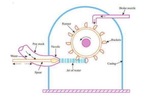
Fig 1: Parts of Pelton Turbine
1. Nozzle and Flow Regulating Arrangement
The water from source is transferred through penstock to which end a nozzle is provided. Using this nozzle the high speed water jet can be formed. To control the water jet from nozzle, a movable needle spear is arranged inside the nozzle.
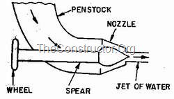
The spear will move backward and forward in axial direction. When it is moved forward the flow will reduce or stopped and when it is moved backward the flow will increase.
2. Runner and Buckets
A Pelton turbine consists of a runner, which is a circular disc on the periphery of which a number of buckets are mounted with equal spacing between them. The buckets mounted are either double hemispherical or double ellipsoidal shaped.
.
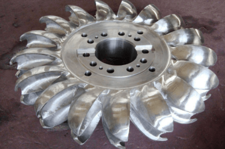
Runner and Buckets of Pelton Wheel
A dividing wall called splitter is provided for each bucket which separates the bucket into two equal parts. The buckets are generally made of cast iron or stainless steel or bronze depending upon the head of inlet of Pelton turbine
3. Casing
The whole arrangement of runner and buckets, inlet and braking jets are covered by the Casing. Casing of Pelton turbine does not perform any hydraulic actions but prevents the splashing of water while working and also helps the water to discharge to the tail race.
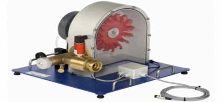
Pelton Turbine Model With Casing
4. Braking Jet
Braking jet is used to stop the running wheel when it is not working. This situation arises when the nozzle inlet is closed with the help of spear then the water jet is stopped on the buckets. But Due to inertia, the runner will not stop revolving even after complete closure of inlet nozzle.
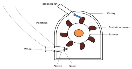
To stop this, a brake nozzle is provided as shown in figure . The brake nozzle directs the jet of water on the back of buckets to stop the wheel. The jet directed by brake nozzle is called braking jet.
Working principle of pelton wheel:
Let’s understand by the figure or layout of the hydropower plant, The water is stored at the high head. From there it comes through the penstock and reaches the nozzle of the Pelton turbine. The nozzle increases the kinetic energy of the water and directs the water in the form of the jet.
Now, the jet of water from the nozzle strikes the buckets (vanes) of the runner. So that the runner rotates at very high speed and the quantity of water striking the vanes or buckets is controlled by the spear present inside the nozzle and then the main important process is the generator is attached to the shaft of the runner which converts the mechanical energy (rotational energy) of the runner into an electrical energy.
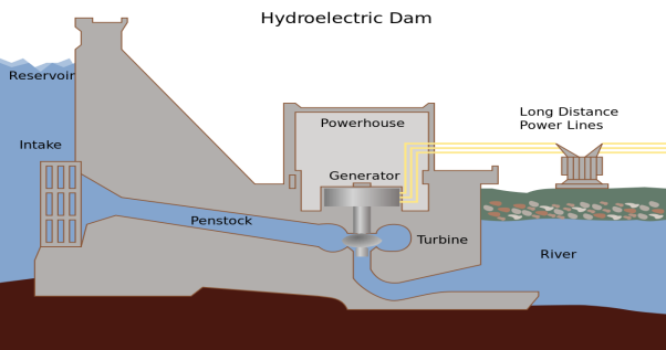
Water flows from the nozzle with high kinetic energy along the tangent to the path of the runner and when the jet of water comes in contact with the bucket, it exerts a force on the bucket called as Impulse force.
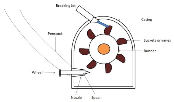
In order to control the quantity of water striking the runner, the nozzle fitted at the end of penstock is provided with a spear or needle fixed to the end of a rod.
In this process, the momentum of the water is transferred to the turbine. The impulse force produced due to this momentum of water causes the turbine to rotate.
The double Semi ellipsoidal buckets split the water jet into two halves which helps in balancing the wheel (runner). This ensures a smooth transfer of the fluid jet to the turbine wheel.
For maximum power and efficiency, the turbine is designed such that, the water Jet velocity is twice the velocity of the bucket.
Advantages of Pelton Wheel:
These are some advantages of Pelton Wheel Turbine:
- The Pelton turbine is the most efficient of hydro turbines.
- It operates with a very flat efficiency curve
- Each bucket splits the water jet in half, thus balancing the side-load forces or thrust on the wheel and thus the bearings.
- It operates on the high head and low discharge.
- It has a tangential flow which means that it can have either axial flow or radial flow.
- Pelton wheel turbine is very easy to assemble.
- There is no cavitation because water jet strikes only a specific portion of the runner.
- It has fewer parts as compared to Francis’s turbine which has both fixed vanes and guided vanes.
- The overall efficiency of the Pelton turbine is high.
- Pelton wheel turbines, both first law and the second law of motion are applied.
- The main advantages are that In this turbine, the whole process of water jet striking and leaving for the runner takes place at atmospheric pressure.
Disadvantages of Pelton Wheel:
- The efficiency decrease very quickly with time.
- The Turbine size runner, generator and powerhouse required is large.
- The variation in the operating head is difficult to control because of high heads.
Application:
Pelton turbine is used in the hydroelectric power plant where the water available at high head i.e. 150 m to 2000 m or even more. In hydroelectric power plant, it is used to drive the generator attached to it and the generator generates the mechanical energy of the turbine into electrical energy.